A.F.C. with silicon capacitors for RTTY reception
This article will describe a relatively simple a.f.c. circuit designed to be used for RTTY frequency-shift keying operation. It does not use vacuum tubes, transistors, or amplifiers of any kind.
Any RTTY operator who sits with one hand on the tuning dial of his receiver will appreciate the addition of automatic frequency control. This little circuit will take care of any drift in your receiver as well as the other fellow's transmitter drift.
Principle of operation
Fig. 1 shows a schematic diagram of the a.f.c., complete with all values. Two tuned circuits, which use 88 mH toroids, set the locking frequency. One is tuned 125 c.p.s. above and the other 125 c.p.s. below the frequency to be controlled. I chose the space frequency, 2975 c.p.s., since the Qs of the tank circuits will be higher than on the mark frequency of 2125 c.p.s. However, the circuit should operate just as well on either frequency. CR1 and CR2 are silicon diodes and are used in a discriminator circuit. By using a d.p.d.t. switch, the diodes can be switched back and forth so that the control will operate whether the b.f.o. is above or below the intermediate frequency.
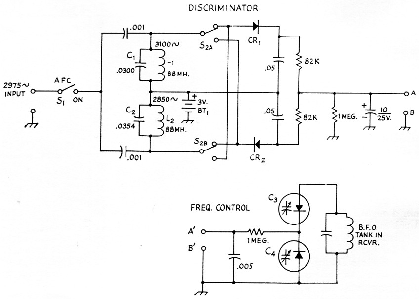
Fig. 1. Circuit diagram of the audio a.f.c. circuit. Capacitances are in µF, resistances are in ohm, resistors are ½ watt. Capacitor with polarities indicated is electrolytic; except as indicated below, others may be paper or ceramic as convenient. Terminals A-A' and B-B' should be connected by a shielded lead. Circuit in lower drawing should be installed close to b.f.o. coil in receiver. The discriminator can be external to the receiver.
| BT1 | Two penlight cells in series. |
| C1,C2 | Values given are calculated for 88 mH coils. Use good-quality 0.03 µF paper capacitors and parallel with low values to tune circuits to desired frequencies. C1L1 and C2L2 should be tuned to equal numbers of cycles above and below 2975 c.p.s., respectively. |
| C3,C4 | Capacitor diodes; see text (Pacific Semiconductor Varicap type PC-113-22). |
| CR1,CR2 | Silicon diode 1N2069 (Texas Instruments) or 1N1692 (G.E.). |
| L1,L2 | 88 mH toroid (see text). |
| S1 | S.p.s.t. toggle. |
| S2 | D.p.d.t. toggle (for reversing control voltage). |
The tuned filters and discriminator section can be mounted on a small board and built into or near the terminal unit. The rest of the circuit, which consists of four small components, can easily be mounted in the receiver. A shielded cable should be used between the discriminator output and the receiver in order to eliminate 60 cycle pickup. The input signal is coupled directly from the filter in the terminal unit.
C3 and C4 are silicon capacitors commercially known as "Varicaps." They are actually silicon diodes, and have the familiar forward and reverse characteristics. To eliminate conduction in the forward direction from the voltage present in the tank circuit, two capacitors are used back to hack. The diodes are biased in the reverse direction by the d.c. control voltage. The capacitance decreases with increasing control voltage and increases as the control voltage decreases. It varies essentially as 1/√v, when v is the control voltage.
Whenever the frequency of the input signal to the a.f.c. unit tries to change, the discriminator bridge goes out of balance and a corrective voltage is applied to the voltage-sensitive capacitors. This causes the b.f.o. to shift frequency automatically until the correct beat note is obtained.
Performance
The frequency regulation obtained with this unit has been more than satisfactory on all bands. The amount of frequency drift that it can correct is limited only by the passband of the receiver. I use the Heathkit Comanche, which has a 3 kc passband. The other fellow's transmitter can drift 1500 c.p.s. before I lose copy on my teleprinter!
The a.f.c. is especially useful on the higher bands. While a member of a ten-meter net in Cleveland, Ohio, the author, recently K8DXV, had no trouble getting solid copy while relaxing or making a pot of coffee.
The a.f.c. unit just described can be built in leas than two hours and costs about. $10.00. The whole thing is powered by two penlight batteries that have to furnish only microamperes of current, and should give shelf life. The Varicaps used are rated at 22 pF at 4 volt, and have a capacitance change of 3 to 4 pF per volt. Any other type with the necessary capacitance range can be used. The required sensitivity in pF per volt may differ somewhat with different b.f.o. circuits - e.g., whether the b.f.o. tank is low-C or high-C - and the intermediate frequency. However, it is recommended that the circuit as given be tried first. If more sensitivity is needed, parallel Varicaps can be used. Another possibility is to use 1.5 instead of 3 volt bias. This will move the operating point to a region where the capacitance change per volt is greater, but the capacitance itself is also greater -- of the order of 40 pF In either case, the effect of the shunt capacitance introduced by the voltage-sensitive capacitors must be taken into account since it has considerable bearing on whether or not the b.f.o. can be retuned to the proper frequency after adding the capacitors.
Nicholas G. Muskovac, K1RYY.