A novice three band antenna system
Coaxial feed with harmonic protection.
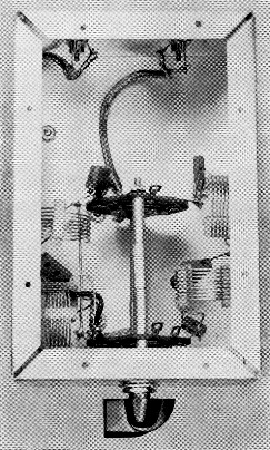
Half-wave filters for the 3.5 and 7 Mc bands. The switch lets the user select either filter as required, and also has a "straight-through" position for cases where the filters are not needed. The two coils and three capacitors at the right are the components of the 80 meter filter; similar components at the left are for 40 meter. Note positions of coils to reduce coupling between them.
A simple antenna system for Novice three-band operation, 80, 40 and 15 meter, can be made up by paralleling two dipoles. The two dipoles are 80 and 40 meter half-wavelength wires both fed at the center with coaxial feed line. The antenna is shown in Fig. 1. Practically all novice transmitters have pi-network output tank circuits and are designed to work into 50 ohm loads. This antenna system will present essentially such a load to the transmitter. If there is a mismatch, it can easily be handled within the adjustment range of the amplifier controls.
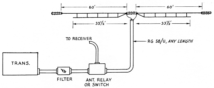
Fig. 1. Three-band Novice antenna system. The feed line, RG-58/U, can be any length. An antenna relay or switch should be installed so the same antenna can be used for receiving as well as transmitting. If a low-pass filter is needed, it should be installed between the transmitter and half-wave filter.
The only serious drawback to this type of system is that unless certain precautions are taken, there is always the danger of harmonics being radiated, which can result in a warning from the FCC. However, this is easily taken care of by the use of a filter inserted in the feed line. The filter requires no adjustment; it is switched in or out as required for whichever band is used.
The antenna
The antenna is made up from a 100 foot length of open-wire TV-type transmission line. Either the close-spaced 300 ohm type or the wider-spaced (about 1½ inch) 450 ohm line can be used. The 80 meter portion is actually longer than 100 feet (120 feet over-all), but the extra length can be obtained from the wire you remove for the 40-meter antenna. When you buy the open-wire line be sure to measure the length - in the roll we bought we found that instead of 100 feet there were actually 104 feet. Cut the line in the center and scrape the enamel insulation from all four ends. Don't be deceived by the appearance of the wire; it does have an enamel covering, so be sure to remove the enamel before making any connections. When the wire ends are cleaned they can be fed through the ends of the center insulator. Fig. 2 shows the details for making the feed-line connections to the center of the antennas.
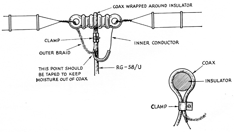
Fig. 2-Sketch showing the method of attaching the feed line to the antenna of the center insulator. Be sure to tape the end of the coax with a waterproof tape to keep any moisture from getting :nto the coax.
Next, remove enough wire from each side of the open-wire line so that you end up with a dipole 33½ feet long each side of the center insulator (67 feet over-all), as shown in Fig. 1. You'll find that if you use a pair of side cutters you can easily break the wire-spreader insulators of the open-wire line. However, only remove those insulators beyond the 33½ foot point. The remaining insulators are needed to keep the 40 and 80 meter dipoles from shorting to each other. Using the wire you have removed, you can add enough at each end of the 100-foot length to make up the 80 meter dipole. This should be 60 feet long each side of the center insulator, or 120 feet over-all when completed. However, allow about six inches length at each end (121 feet over-all) on the 80 meter antenna, the extra six inches for wrapping around the end insulators. Be sure to scrape the enamel covering from the wires at the ends when you add the extra lengths. Solder all connections. Put on the end insulators and the antenna is completed.
When you install the antenna, make every effort to get it as high as possible above the ground. If possible, install pulleys to raise and lower the antenna. Nylon ¼ inch-diameter line makes excellent halyard material.
The half-wave filter
The filter unit shown in the photograph and Fig. 3 consists of two filters, one for 80 and another for 40. The cutoff frequency for the 80 meter filter is approximately 5 Mc. It will attenuate any signals higher than 5 Mc but permit your fundamental signal to reach the antenna without being attenuated. This, of course, means that 80-meter harmonics won't be able to reach the antenna and cause you trouble with the FCC. The 40 meter filter cutoff frequency is about 9 Mc, so it will take care of any spurious signals above this range. There is no point in adding a 15 meter filter to the unit because if harmonics from this band are going to be a problem, a low-pass filter should be inserted in the line. A low-pass filter usually has a cutoff frequency slightly above 30 Mc, and any harmonics above this range will be attenuated. In other words, the harmonics that could cause TVI should be handled with a low-pass filter.
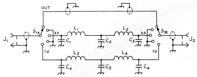
Fig. 3. Circuit diagram of the half-wave filter. For Novice power, 500 volt mica capacitors are satisfactory.
| C1,C3 | 75O pF mica. |
| C2 | 1500 pF mica. |
| C4,C6 | 500 pF mica. |
| C5 | 1000 pF mica. |
| J1,J2 | Phono jacks or coax chassis fittings. |
| L1,L2 | 2 µH; 8½ turns No. 20, 1 inch diam., 16 turns per inch. |
| L3,L4 | 1.2 µH, 6 turns No. 20, 1 inch diam., 16 turns per inch. (All four coils can be made from a single length of B & W Miniductor, type 3015). |
| S1 | Rotary, 2 sections, 5 positions, 1 pole per section (Mallory Hamswitch type 1510. |
Making the filter
The filter is built into a 3 × 4 × 6 inch aluminum chassis. The four coils required for the two filters are made from a single length of Miniductor coil stock, No. 3015. When cutting the coils from the original stock, allow a couple of extra turns on each coil. These extra turns can then be unwound to provide sufficient lead length for attaching to the terminals of S1. Two phono jacks are used for connectors on the filter. If desired, the more expensive coax chassis fittings, type SO-239, can be used.
The leads from the jacks to the terminals on S1 are made with coaxial line, type RG 58,U, the same as used for the antenna feed line. Remove the black vinyl covering from the coax, exposing the outer braid. When making the connections from the jacks to the switch, keep the exposed inner conductor lead as short as possible. This is done in order to reduce any harmonic pickup around the filter sections. In other words, all the signal should go through the filter, with minimum leakage around it. Ground the outer braid of the coax at the jack end and also at the switch end. The switch end can be taken care of by installing a soldering lug as close as possible to the switch contact and grounding the shield at the solder lug. The coils and capacitors for the 80 meter filter are mounted on one side of the switch and the 40 meter unit on the other side. The coil sections should be installed as shown in the photographs in order to reduce any stray pickup between the two filters. In addition, the switch sections are single-pole, five positions each. Only three of the positions are used - filter out, 80 meter, and 40 meter. In order to reduce any chance of pickup between the switch contacts, alternate contacts are used for the connections. In other words, the first contact is the straight-through position, then an unueed contact, and then 80 meter. In addition, the unused contacts are grounded to the chassis. A bottom plate should be installed on the chassis in order to make it "r.f. tight."
Using the system
Use a short length of coax to Connect the filter to the transmitter. The filter can be installed at any convenient place at the operating position. Then connect the feed line to the filter and the system is ready for operation.
Incidentally, the circuit works the same in both directions, so it doesn't make any difference which side of the filter is used for input or output.
Switch your transmitter to whichever band you want to use and also switch the filter to the same band. For 15 meter the filter is set in the straight-through position. It is very important that you switch the filter when you change bands. If, for example, you tune up your rig on 80 with the filter switched to 40, you'll more than likely burn out the capacitors in the filter. You must remember to have the filter and transmitter on the same band!
Several measurements were made on the two dipoles to see what they "looked" like on the different amateur bands. On 80 and 40 meters, the antennas were resonant in the Novice bands, using the lengths shown in Fig. 1. The standing-wave ratio was less than 1.5 to 1 at resonance on both bands and remained fairly flat across the Novice segments of the bands. On both 80 and 40, the s.w.r. rose to about 5 to 1 at the band edges (3500-4000 and 7000-7300). The s.w.r. was about 3 to 1 at the lowest point when the system was used on 15. However, this is well within the tuning and adjustment range of nearly all Novice transmitters. When you pass your General you'll find that the same antenna can be used on 10 meters, as our tests showed the s.w.r. to be no worse than 4 to 1 at the band edges, dropping to less than 2 to 1 at the best frequency. On 20 meters, the system wasn't satisfactory, as it showed a high s.w.r. (over 5 to 1) across the band.
All of the above-mentioned tests were made with the antenna 30 feet above the ground and in the clear. Thanks go to Carl Dane, W1FXK, for furnishing the refreshments, swimming pool, and his vacation time while making these tests.
Lewis G. McCoy, W1ICP.