An "ultra-linear" modulator
The "ultra-linear" circuit, widely used in high-quality audio power amplifiers, has its uses in plate modulation, too. The circuit reduces distortion and improves regulation while retaining the high power output and sensitivity of Class AB1 audiotetrodes and pentodes.
Tapped screen circuit for pentodes or tetrodes.
This modulator makes use of the chassis and most of the parts of a high-fidelity power amplifier, but a similar layout using regularly available components can be constructed from the circuit of Fig. 2.
The ultra-linear mode of operation has been successfully used in the output stages of high-fidelity audio amplifiers for the past decade or so. This type connection, shown in Fig. 1, has been described as a means of applying power feedback around a stage of power amplification. It is recognizable as a method of operation which is somewhere between triode and pentode. The screens are connected to a tap on the output (or modulation) transformer and - unlike pentode operation - thereby deliver some power to the load, but not as much as they would if the tube were triode connected, with the screen tied directly to plate. The connection shown in Fig. 1A is most frequently used. The separate windings shown at B are necessary if the tube requires substantially different plate and screen voltages. Transmitting tubes, such as the 6146, have been used successfully this way.
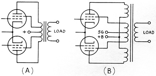
Fig. 1. Tapped-screen power-amplifier circuit.
(A) As used when the same d.c. voltage can he applied to both screen and plate.
(B) As used when different plate and screen voltages must be used.
Ultra-linear operation, also known as "tapped-screen" - perhaps this term would be preferred by amateur operators - has been shown to exhibit substantial advantages over both triode and pentode operation, particularly when used with tubes designed for it. It combines the high power output of pentode operation with the low distortion and low output impedance of triodes. In addition, compared with pentode operation it is uncritical of the load into which it works, and is somewhat more efficient over-all, since the screen is contributing power to the load and not just producing heat. Because of this, substantially higher screen voltages and maximum-signal inputs than shown in maximum rating charts for pentodes can be used.(1)
These characteristics make tapped-screen operation ideal for modulator service, and tubes are available which will deliver anywhere from 5 to 100 watt in tapped-screen push-pull. The problem, however, is finding a suitable modulation transformer, since none to the best of our knowledge has been designed for tapped screens.
Having come into possession of an old Scott Laboratories audio amplifier, with its mounted tube sockets, husky power transformer and handsome chrome chassis, and possessing an extra pair of Genalex KT88s as well, we decided to tackle the problem.
Multimatch transformers seemed the best solution, and, after investigation, it turned out that the Stancor A-3893 was perfectly suited to matching both the 4000 ohm plate-to-plate load and the 40 per cent screen-tapping requirements of the KT88s.(2) In addition, the power transformer already in the amplifier, when used with silicon rectifiers in a conventional full-wave capacitor-input circuit, delivered precisely the plate voltage required by the tubes. Of course, any other arrangement that is capable of supplying 450 volt, and has an ICAS rating of 200-250 mA, may be used.
The final circuit is shown in Fig. 2. Aside from the output stage, the circuitry is entirely conventional, with great pains taken to avoid hum and r.f. in the audio circuit. The resistor shown shielded is connected directly to the microphone connector, with its body inside the connector, and is bypassed as closely as possible to the other side of its body. The additional shunting capacitors serve both to bypass any remaining r.f. and, with the coupling capacitors, to shape the frequency response for good communications quality.
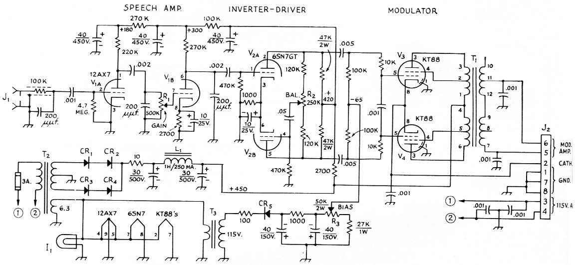
Fig. 2. Modulator and speech-amplifier circuit. Capacitances are in µF, resistances are in ohm, resistors are ½ watt, except where indicated otherwise. Capacitors with polarities marked are electrolytic; others may be paper, ceramic or mica as convenient.
| CR1-CR5, inclusive | Silicon rectifiers, 600 volt inverse peak, 750 mA (Sarkes Tarzian F-6). |
| I1 | Dial light, 6.3 volt. |
| J1 | Microphone connector, shielded. |
| J2 | Octal socket (A male connector is preferable to avoid exposed voltages on mating plug). |
| L1 | Filter choke, 1 H, 250 mA (Stancor C-2326 or equivalent). |
| R1 | 0.5 megohm composition control, audio taper. |
| R2 | 0.25 megohm composition control, linear taper. |
| R3 | 50,000 ohm, 2 watt composition control, linear taper. |
| T1 | Multimatch modulation transformer, 60 watt. Numbers on circuit refer to Stancor A-3893 transformer. Output winding shown connected for 4000 ohm load. |
| T2 | Power transformer; 750-760 volts c.t., 200-250 mA; 6.3 V, 5 A (such as Stancor P-8170); 5 V rectifier winding not used. |
| T3 | Filament, 6.3 V, 0.6 A |
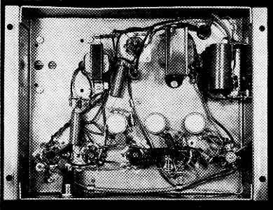
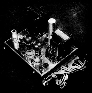
Bottom view of the revamped amplifier shows that for the most part the layout may be whatever the constructor wishes. Only "touchy" part is the shielding and r.f. filtering of the microphone input, as discussed in the text.
The volume, balance, and bias controls are all screwdriver-adjustment potentiometers, since it is assumed that they will be set only once. The balance control should be set for maximum output or, preferably, for equal voltages at the output tube plates with a signal of 800-1500 cycles fed to the input. The bias should be adjusted for 100 mA total cathode current at zero output. The volume control should be adjusted for only the barest occasional plate-current flicker on loud voice peaks. (The modulator has been used quite successfully with a clipper preceding it. This increases talk power considerably.)
All power and output connections, as well as the output-tube cathodes, are connected to an octal socket at one end of the modulator. This is connected to the transmitter via a single 6 conductor cable so that the modulator need not be left on the operating table nor connected by a tangle of wires. Make sure that the leads going to the modulated r.f. stage can handle the sum of both the d.c. voltage to the final and the peak audio, which is equal to twice the d.c. At the operating position, the cathode connection may be used with a d.c. milliammeter to monitor the modulator cathode current or may be grounded by either the antenna relay or the standby-transmit switch. The transmitter's meter can be used by replacing the meter switch with one having one more position.
Curves of output vs. load resistance are shown in Fig. 3. The dotted portions of the curves should not be used, since distortion will rise in these regions. The modulator will deliver 40 watt into any load from 500 to 10,000 ohm, and 50 watt into loads from 500 to 750, 1300 to 2000, and 2500 to 6000 ohm. Almost all 50-120 watt transmitters will be matched somewhere in this range.
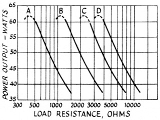
Fig. 3. Power output vs. load resistance for the amplifier shown in the photographs, measured at 1000 c.p.s., using multimatch modulation transformer with primary connected as shown in Fig. 2. Secondary connections as follows: A, load to terminals 7 and 10; 8 and 11 joined. B, load to 7 and 10, 7-12 and 9-10 joined. C, load to 8 and 11; 9-12 joined. D, load to 7 and 11, 9-12 joined.
The under-chassis view of the modulator shows a shielded cable running under the chassis from the octal socket to the 12AX7, and another shielded cable running in parallel with the output cable. After the pictures were taken, we found that we could eliminate neither the r.f. in the modulator nor the audio feedback with this arrangement, so we mounted a microphone connector right beside the 12AX7, bypassed it as described earlier, and ran a separate microphone cable.
The modulator is at present being used by WA2JY0, to whom thanks are due both for assisting in the tests and for permitting the author to modify his transmitter for plate modulation.
Notes
- The screen input under quiescent or no-signal conditions must still stay within ratings. - Editor.
- The 40 percent figure - i.e., screens tapped across 40 per cent of the primary turns - is in the optimum region for most tubes, and except for some rather special requirements that are of interest in high-fidelity amplifiers but not in amateur communication, is not highly critical. Values between about 25 and 50 per cent will result in developing maximum power output with relatively low distortion. - Editor.
Robert M. Voss, W2HTN.