Single-switch RTTY control
Simple system for transmit/receive/print.
This article describes the use of a single switch, normally on the transmitter and functionally labeled TRANSMIT-STAND-BY, to permit the following RTTY operations:
- While in the STAND-BY position, the selector magnets on the teleprinter are in series with a 60-ma. (or other value, depending upon the requirements of the magnets) supply and the TU (converter) output for routine receiving operations.
- When in the TRANSMIT position, the printer keyboard pulses a relay that has one set of contacts in series with a 60-ma. loop containing the selector magnets, thus providing local copy of transmissions. The other set of contacts pulses the f.s.k. circuit.
- Also, by the installation of an additional switch, the machine can be used as a station typewriter.
One sure-fire method of checking the frequency shift and quality of one's own RTTY transmissions is to copy your signal through the receiver and TU to provide local copy. This method, while satisfactory if you are transmitting and sending on the same frequency, cannot be accomplished if you are a kilocycle or more off frequency. This point was brought home during the recent Armed Forces Day RTTY contest when some RTTYers in the amateur bands attempted to establish contacts with military stations on various frequencies outside the amateur bands. If the station lash-up consisted of a scheme to make local copy by picking up the transmitted signal in the receiver, it was tough sledding - if you remained on the military frequency, you could not monitor your sending.
ZS1FD, in his "Case history of RTTY in foreign lands" (RTTY, May, 1961), laid it on the line by saying, I "just could not figure out why so many fellows insisted on making local copy by their own signal in the receiver." Of course, the reason for this is a desire to maintain monitoring, via the TU, the frequency shift of the transmitted signal and exactly what you may expect the receiving station to be printing. This inflexible control seems unnecessary. Normally the usual 850 cycle shift is set and seldom needs resetting.
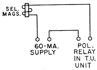
Fig. 1. Basic RTTY selector magnet circuit.
Before describing the rather simple circuit of Fig. 2, it must be assumed that the RTTY station has at least a t.r. switch that is capable of performing antenna switching, receiver muting, and other normal functions. This being the case, we have the ability to either add a relay to the t.r. switch circuit, or add a couple more poles to the relay that you may be using to duplicate the functions of K2. However, this gets ahead of the story.
In RTTY, keep in mind that the teleprinter is basically a simple electrical apparatus consisting of a pair of selector magnets and a glorified switch called a keyboard. Add a 115 volt a.c. line for the motor, and that's it - ignore all the rest of the wires and you'll agree that the printer is a simple electrical device. Now, getting down to business, in the receiving position the keyboard is not in the circuit. Most of us get the selector magnets to pulse from a polar relay in the TU in series with a 60 mA, current supply, as shown in Fig. 1. If you desire to send and copy what you send without using the station's TU, it's a cinch that you need the selector magnets, current to pulse them, and pulses from the keyboard to take the place of the polar relay. In addition, don't forget the most important function of keying the f.s.k. circuit.
Now refer to Fig. 2, which is shown in the STAND-BY position. Studying tjih, we see that the circuit of Fig. 1 is still intact. Let's go to TRANSMIT and follow this: K2 breaks one leg of the polar relay that was in the receive circuit and, at the same time, closes the keyboard circuit. This activates relay K1 and, with the keyboard in its "rest" position, the f.s.k. is pulsed in the "mark" position and the selector-magnet circuit is closed, waiting for the keyboard to be hit. When a key is depressed, K1 pulses the selector magnet for local copy and pulses the f.s.k. for transmitting - regardless of the station receiver and the station's TU.
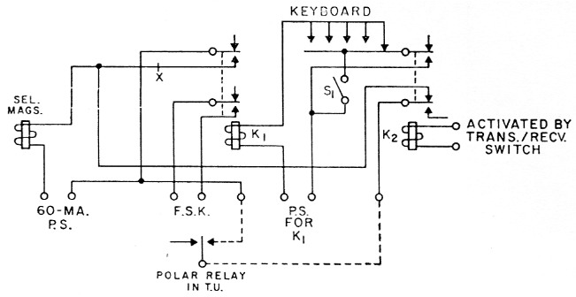
Fig. 2. Circuit of the control system.
| K1 | Fast-respond d.p.d.t. d.c. relay, 120 volt, d.c., 2500 ohm (Clare C-27998). |
| K2 | D.p.d.t. a.c. relay (Advance MG2C115VA or similar). |
| S1 | Toggle or other s.p.s.t. switch. |
By closing S1 while in the RECEIVE position, the teleprinter can be used as a local (off the air) typewriter, a practice we all follow. The author also uses this switch when receiving in upper case by merely closing the switch and pressing the LTRS button on the keyboard and then opening the switch. This brings the machine down to lower case for correct printing. When using the machine as a typewriter, you may have to pull the plug from the polar relay temporarily if the polar relay contacts are touching the armature.
Any of a variety of relays could perform the functions of K1 and K2. Those I use are listed under Fig. 2. A whole lot will depend upon what is available to the builder, but anyone in the RTTY business who has fought the battle of the polar relay should have no trouble with simple relays. However, it must be noted that K1 should be a fast-keying relay, capable of reacting to the 22 ms pulses.
For RTTYers who have TUs that do not use a polar relay, do hot despair. In this type of arrangement, the selector magnets are fed directly from the output of amplifier tube(s). The circuit in Fig. 2 can be adapted to this arrangement. If you want local copy without use of the station receiver and TU, you will need a 60 mA supply (you can't get something for nothing here). Break the line at X, insert the 60 mA supply at this point, short the 60 mA terminals shown in Fig. 2, and you'll have local copy as described above. (In this case, disregard the polar relay and the location of the 60-ma. supply as originally noted in Fig. 2.)
One more point, and we'll let you go. The author uses this circuit primarily on MARS frequencies where the c.w. identification requirement doesn't exist. However, when using RTTY in the amateur bands, a single-pole single-throw, spring-loaded, normally closed switch should be inserted across the standard telegraph key. When identifying on c.w., merely open the spring-loaded switch, identify with the key, using the other hand and, when the hand holding the spring-loaded switch is released, the printer is ready to send. Some amateurs use the SEND/ AEC MC switch on the printer for this function, but this unnecessarily complicates the wiring of the machine, and we previously agreed that it should be a very simple device.
James H. Flynn, Jr, W4ISM/A4ISM, Ex-W2BDI.