A wide-range transmatch
Matching network for 80 through 10.
This matching circuit uses a capacitor divider for smooth variation of loading adjustments and for simplifying band switching. Practically any antenna system can be matched to 50 or 70 ohm transmitter output. A Monimatch is incorporated for checking the matching adjustments.
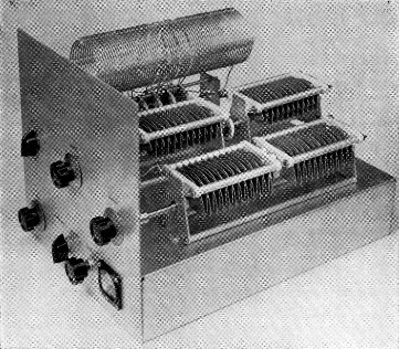
The wide-range 500 watt transmatch. In this view of the chassis the coil and switch assembly are on the far side. In the center are C2 and C4, with C3 on the near side. The controls along the bottom front, from the left, are for C1, S1 and R3 in that order.
The transmatch shown in the photographs and Fig. 1 will match your transmitter's 50 or 70 ohm output to antenna loads as low as 10 ohms and as large as 4000 ohm. To handle this wide range, the usual procedure would be to have several coils with a multiplicity of taps, leading to a very complex switching arrangement if band switching is desired. In this unit, however, there are no taps for feeder connections. The "tapping" is accomplished by a capacitor-divider system consisting of C2, Ca and C4. The three variable capacitors are connected in series across L1.
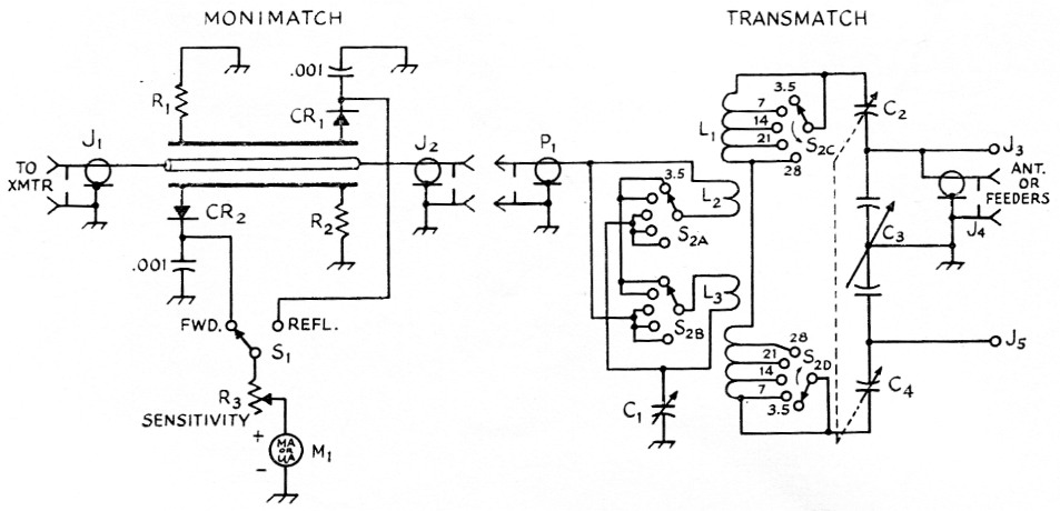
Fig. 1. Circuit diagram of the transmatch and Monimatch.
| C1 | 250 pF variable, 0.045 inch spacing for high power (Johnson 250E20); 0.025 inch spacing for low power (Hammarlund MC-250-M). |
| C2,C4 | 100 pF variable, 0.125 inch spacing for high power (Johnson 100E45); 0.025 inch spacing for low power (Hammarlund MC-100-M). |
| C3 | 100 pF per section, dual variable, 0.125 inch spacing for high power (Johnson 100ED45); 0.025 inch spacing for low power (Hammarlund MCD-100-M). |
| CR1,CR2 | 1N34A germanium diodes. |
| J1,J2,J4 | Chassis type coax receptacles, type SO-239. |
| J3,J5 | Feed-through insulators. |
| L1,L2,L3 | See Fig. 2 and text. |
| M1 | 0-1 mA or less; see text. |
| P1 | Coax plug, type PL-259. |
| R1,R2 | For 50 ohm bridge, 150 ohm, ½ watt composition; for 70 ohm bridge, 100 ohm, ½ watt composition. |
| R3 | 20,000 ohm control, linear taper. |
| S1 | Rotary, 1 pols, 2 positions (Centralab type 1460). |
| S2 | Ceramic rotary, 4 poles, 5 positions, 1 pole per section, 4 sections (Centralab index type P-122 with type "T" or "X" sections). |
Either unbalanced or balanced feeders can be connected to the transmatch at J3J5 shown in Fig. 1. The load presented to the circuit at this point is easily matched to the transmitter output by adjusting C2 and C4 (which are ganged) along with C3 and C1. Adjusting three controls to arrive at a match may sound like quite a chore, but actually is very simple, as will be explained later.
Another feature of this unit is the use of a single length of coil stock for both the primary and secondary. This practically eliminates the problem of exact duplication. Note that the link, L2L3, is actually two coils. For 80 and 40 meter, the two coils are connected in series to provide an 8 turn link. On 20, 15 and 10 the coils are connected in parallel, resulting in the equivalent of a 2 turn link which works out just right for these bands, This scheme keeps the link at the exact center of the coil on all bands, thus maintaining symmetrical coupling to the secondary windings.
A Monimatch is included as a matching indicator. Some type of bridge is required to show when the unit is correctly adjusted. If you already happen to own a Monimatch or similar device, this part of Fig. 1 can be eliminated.
As designed and shown, this unit will handle about 500 watt on c.w. or s.s.b. and about half that power on a.m. phone. Of course, the Novice can only run 75 watt input, but most of the gang seem to want more power when they get their "Generals," so this unit was constructed with that thought in mind. However, some examples of capacitors for the 50 to 100 watt level are given in Fig. 1. The coil remains the same for either power - it's simple that way and there isn't enough difference in coil ccst to warrant using a different coil.
Speaking of cost, the capacitors for the 500 watt unit are not cheap. However, there should be plenty of capacitors to be found in junk boxes, and so if you don't have any around your own shack, see what the neighboring hams have. There is nothing sacred about the 100 pF maximum capacitance values given for C2, C3 and C4. If you can find some that run higher than this, don't be afraid to use them. You should still come up with a workable transmatch. Don't use smaller values, though, as less capacitance will limit the range over which you can match.
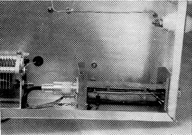
Close-up view of the Monimatch. The pickup wires are held in place by the insulating spacers.
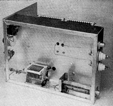
This bottom view shows the arrangement of parts below deck. The link capacitor, C1, is mounted on the chassis side. In the lower foreground is the Monimatch unit.
Construction details
The complete transmatch, including the Monimatch, is built on a 3 × 10 × 14 inch aluminum chassis. The front panel is made from a 10 × 10 inch piece of aluminum sheet stock. A study of the top-view photograph will show you the layout. C3 is mounted directly on the chassis top along one side. Between C3 and the coil and switch assembly are C2 and C4. These two capacitors are ganged with an insulated shaft coupling. In addition, they must be insulated from the chassis and the panel. Four one-inch steatite standoff insulators are used to hold the capacitors off the chassis. The two output leads that go to J3 and J5 are taken off the rotor mounting points between the two capacitors. These leads run down below chassis to the connectors through two rubber grommets.
Fig. 2 shows how to make L1, L2, and L3. Cut a total of 66 turns from a length of coil stock, making sure to leave enough lead length at each end of the coil for connections to the switch. At 28½ turns from each end of the coil cut the wire and unwind ½ turn from the support bars. This will give you two coils of 28 turns and another of 9 turns. Cut the 9 turn coil at the center and unwind the ½ turn, leaving two coils of 4 turns each. The two 28 turn coils are connected at the center by soldering the two center leads together.
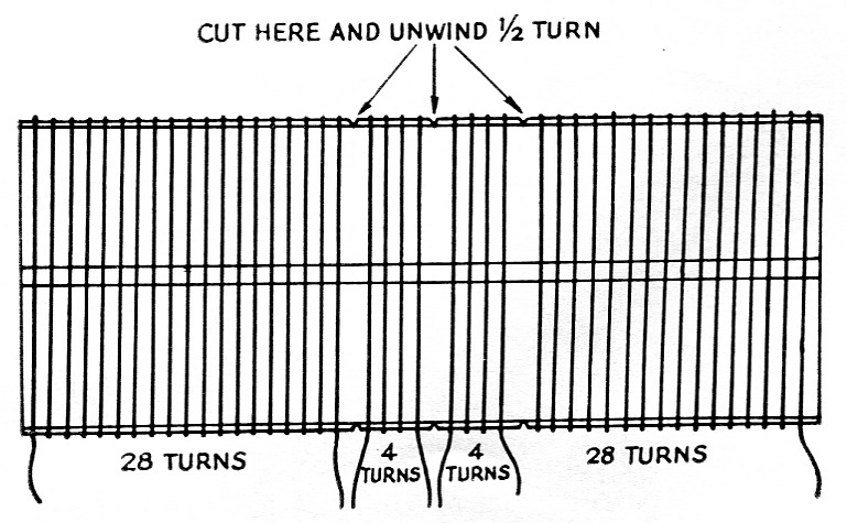
Fig. 2. This drawing shows how to make the coil assembly. Not shown are the taps needed for changing bands. The tap points listed below all are counted from the outside ends of the coil.
| 7 Mc | 12 turns. |
| 14 Mc | 23 turns. |
| 21 Mc | 25 turns. |
| 28 Mc | 26 turns. |
| The coil stock in 3 inches in diam., No. 14, 8 turns per inch, (lllumitronic Air Dux 24081). | |
The coil assembly is supported by its own leads and is mounted over S2. The switch assembly S2 is made from a Centralab P-122 index and four steatite single-pole, five-position switch sections. Either type T or X is suitable. Two switch mounting brackets are used to support the switch assembly.
A word of explanation for those readers who are not familiar with the Monimatch: This unit is an s.w.r. bridge designed to "sample" both the forward and reflected powers. This power is converted from r.f. to d.c. by CR1 and CR2, and the d.c. is read on the meter, Ml. When the meter reads full scale in the forward position, a zero reading in the reflected position indicates that the transmatch is correctly adjusted.
The Monimatch is mounted in a 2¼ × 2¼ × 5 inch aluminum box (Bud Minibox CU-3004A). Chassis-type coax fittings (SO-239) are mounted in the center of each end of the box. A piece of 4 inch o.d. copper tubing, 4_5/8 inch long, is connected between the two inner pins of the coax fittings. The two pickup leads for the bridge are 334 inches long and made from No. 14 solid wire. They are held in the proper position by two insulating spacers. Details of the spacers are shown in Fig. 3. The spacers can be made from polystyrene or bakelite.
Two flat strips of copper, 5/8 inch wide by 4_7/8 inch long, are installed as shown in the photograph. The method of mounting the strips is quite simple. Solder a lug to each end of each strip, allowing the end of the lug with the screw hole to project beyond the edge. Bend this part of the lug up at right angles to the strip. The strips are then mounted by using the top and bottom screws and nuts of the coax fittings to hold them in place.
When soldering the germanium diodes to the pickup wires, hold the lead of the diode with a pair of pliers between the point of soldering and the body of the diode. This will keep excess heat from reaching the diode and ruining it.
For a 50 ohm bridge R1 and R2 should be 150 ohm, ½ watt resistors. For a 70 ohm bridge use 100 ohm, ½ watt. It is very important that the resistors used be composition or carbon, not wire-wound.
The leads to S1 are brought out of the Monimatch box through two feed-through insulators and run from there to the switch in shielded wire. M1 as shown is a 500 µA meter, but any micro-ammeter, or even a 0-1 milliammeter, can be used.
Adjustment procedure
The transmatch can be used with practically any antenna system. With balanced feed, the feeders should be connected to terminals J3 and J5. A coax line from the antenna should be connected to J4. For single-wire feed, such as a long wire or random-length wire fed at the end, the feeder should be connected either to J3 or J5 and the transmatch chassis grounded to an earth ground.
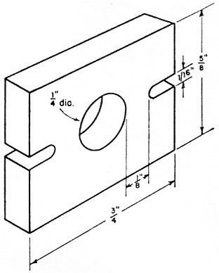
Fig. 3. Dimensions of the insulating spacers used to hold the pickup wires in place in the Monimatch.
Connect a length of coax between the transmitter and the transmatch, using either 50 or 70 ohm coax, depending on which value you built the Monimatch to handle. Feed some power through the system and set Si to read forward power. Adjust R3 for a full-scale meter deflection. Next, set Si to read reflected power and tune C1 and C2C4 for minimum reading. You may not be able to get the reading down to zero (that's what you're shooting for), so try a different setting of C3 and again adjust the other two controls. Once you get the zero reading the transmatch is correctly adjusted for that particular frequency. Make a note of the settings and then proceed to the next band. If you keep an accurate record of all control settings it will be a simple matter to change bands quickly.
If you should encounter an antenna system that cannot be matched, although this is unlikely, the simplest thing to do is to increase or decrease the length of the feeders. A little experimentation will quickly set you up with a "matched" condition.
Lewis G. McCoy. W1ICP.