Single-band grounded-grid linears
Kilowatt units for 10 through 80 meter.
If you do all of your operating on one band, there isn't much point in building a multiband transmitter. On the other hand, if you are a band-hopper, I individual finals requiring little if any adjustment when bands are changed are the ultimate in convenience. Ergo, these grounded-grid units described by K9LKA should have a universal appeal.
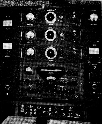
The operating position at K9LKA showing linear amplifiers for 10, 15 and 20 meter mounted in a rack above the receiver.
A great many amateurs using transmitters in the 75 to 150 watt class have one favorite band. Most of these operators would like more output, but hesitate to buy or build a multiband amplifier for several reasons. Aside from the cost, it just doesn't seem sensible to use an amplifier that will operate on five bands when operation on only one is desired. Even the multiband operator will find plenty of argument in favor of the single-band unit plan. Construction is simplified, usually resulting in less-frequent need for servicing, and servicing when required is much easier to handle. No single unit represents a major construction project, and bandswitching can be much less complicated.
Each of the single-band grounded-grid linears shown in the photographs uses a pair of 813s in parallel to provide a one-kilowatt power capability. The tubes, with the screens grounded, operate as high-µ triodes, thereby eliminating the need for a screen supply. Operating Class B, the efficiency of the tubes will run between 65 and 70 Per cent in s.s.b. or c.w. service.
Costwise there is quite a spread. If you're willing to scrounge around, raid the junk box and do some horse trading, you can build each unit complete for less than $30. If you buy all the parts new, the cost will be approximately $60, excluding tubes.
The circuit
The r.f. driving power is fed to the filaments of the two 813s through a 10 nF ceramic capacitor, as shown in Fig. 1. The filament transformer is isolated from r.f. by the bifilar filament choke RFC2.
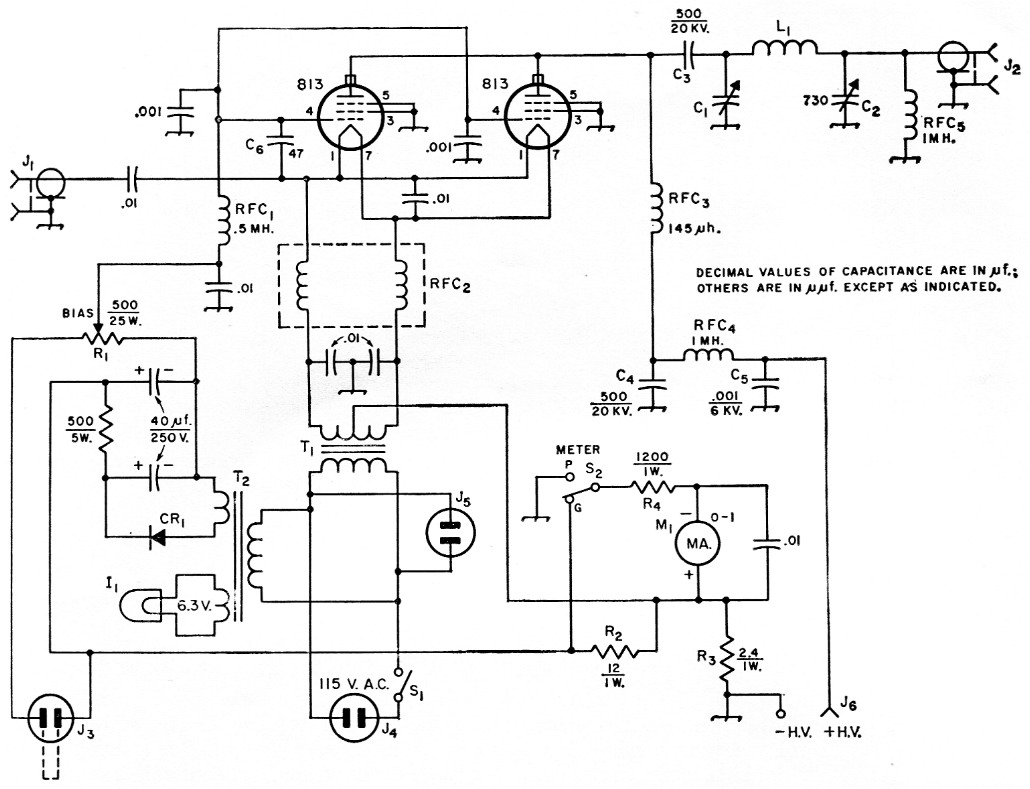
Fig. 1. Circuit used in the single-band high-power linear amplifiers. Capacitors marked with polarity are electrolytic. Resistances are in ohm and resistors are ½ watt unless indicated otherwise.
| C1 | Transmit:ing variable, 0.075 inch minimum plate spacing; 100 pF for 21, 28 Mc and 14 Mc, 150 pF for 7 Mc, 350 pF for 3.5 Mc (Johnson, 100 /154-14, 150E30/154-8, 350E30/154-10, or similar, respectively). |
| C2 | Dual 365 pF variable, broadcast-replacement type, sections in parallel (may be necessary to add 330 pF transmitting mica capacitor in parallel for 3.5 Mc) |
| C3,C4 | Ceramic, TV doorknob type (Sprague 2ODK-T5 or similar). |
| C5 | Disk ceramic (Centralab DD50-102 or similar). |
| C6 | Ceramic (used for stabilizing in 21 and 28 Mc amplifiers). |
| CR1 | 130 V 75 mA selenium rectifier (Sarkes-Tarzian type 75). |
| I1 | 6.3 volt dial lamp. |
| J1,J2 | Chassis-mounting coaxial receptacle (SO-239). |
| J3 | Recessed o.c. connector, male (Hart & Hegeman 80329; takes type 80325 female cable connector. Standard female outlet with male plug may also be used). |
| J4 | Chassis mounting a.c. plug. |
| J5 | Miniature a.c. receptacle (Cinch-Jones 5-302-AB or similar). |
| J6 | High-voltage connector (Millen 37001). |
| L1 | 3.5 Mc 16 turns No. 12 2½ inch diam., 6 t.p.i. (B & W 3905-1 stock). 7 Mc Same as above, 9 turns. 14 Mc 10 turns ¼ inch copper tubing, 1½ inch i.d., turns spaced 1/8 inch. 21 Mc Same, 7 turns spaced 3/16 inch. 28 Mc Same, 4 turns spaced ¼ inch. |
| M1 | D.c. milliammeter, 3 inch. |
| R1 | Wire-wound control (Ohmite H-0156). |
| R2,R3,R4 | Meter multiplier resistors, wire-wound, 5 percent. |
| RFC1 | 0.5 H r.f. choke (National R-300). |
| RFC2 | Bifilar filament choke (B & W FC-15 or similar). |
| RFC3 | Plate choke (National R-175-A). |
| RFC4,RFC5 | 1 mH 300 mA r.f. choke (National R-300). |
| S1 | S.p.s.t. toggle switch. |
| S2 | S.p.d.t. slide switch. |
| T1 | 10 V 10 A filament transformer (Merit P-3146, Stancor P-6461 or similar). |
| T2 | Power transformer: 125 volt, r.m.s., 50 mA; 6.3 V, 2 A (Thordarson 26R38, Stancor PA-8421). |
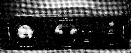
All amplifier units have the same panel design. This unit is the one used for 20 meter. Tuning and loading controls are at the center. The small knob in the lower right-hand corner is for adjusting bias.
A built-in supply delivers 0 to 37 volt of bias to the control grids of the 813s, the value being determined by the setting of R1. With the terminals of J3 open, the voltage rises to -168 V, biasing the tubes beyond cutoff, and no plate current will flow. Shorting J3 reduces the bias to the value selected by adjustment of R1. Leads from J3 should be run to relay contacts, such as auxiliary contacts on an antenna relay which close while transmitting. Cutoff bias on stand-by eliminates the "hash" which often bothers reception, especially when using a t.r. switch.
High voltage is fed to the 813 plates through RFC3 and RFC4. A 500 pH 20 kV doorknob capacitor, C3, is used to isolate the high-voltage supply from the pi-network circuit. The rating of RFC4 is only 300 mA but, since the plate current swings up to 400 mA only on peaks, the rating of this choke is satisfactory.
The two-section variable output capacitor C2, with a total maximum of 730 µµf., eliminates the need for a tap switch and fixed capacitors. The pi-network output of these linears is designed to feed 50- to 70 ohm unbalanced loads.
To obtain separate grid- and plate-current readings, meter M1 is switched across multiplier resistors R2 and R3, respectively. Since the grid circuit is returned to the center tap on the filament transformer, only plate current is read in the PLATE position of 22.
Chassis assembly
The panel is a standard 5¼ × 19 × 1/8 inch aluminum rack-style unit, while the chassis is made up of a pair of See-Zak R45 rails (4 by 5 inch), a pair of R417 rails (4 by 17 inch), and a P517 panel (5 by 17 inch).
First, lay out the P517 panel according to the drilling template of Fig. 2. The rear-view photo will be useful as a check. After locating all holes with a prick punch, drill pilot holes at I and J with a small drill (No. 35 or 36). At this point, mark the outer or mounting side of the P517 panel with a permanent reference mark, such as a file or scribe mark, so that there will be no confusion. Next, place the P517 panel on top of the rear of the rack panel and, after centering it on the rack panel, clamp the two together and transfer the pilot holes at I and J. These are the shaft holes for Cl and C2, so they must match perfectly. Enlarge the two holes in both panels to winch.
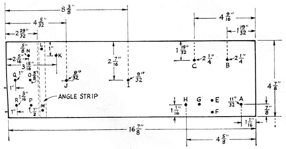
Fig. 2. Sketch showing dimensions and layout of the chassis panel. Lettered points are identified in the text.
Drill all remaining holes whose sizes are indicated in Fig. 2. Exact sizes are not given for holes at H and K. These are for feed-through insulators and should be drilled to fit the ones you have on hand. Mount the 2-contact Jones socket J5 (the a.c. outlet for the ventilating fan) at A.
Cut a piece of ½ × ½ inch aluminum angle 4_7/8 inch long. Using a No. 25 drill, place a hole 5/8 inch from each end and ¼ inch from the outer edge of the angle. Transfer these holes to the chassis panel at points L and M. Submount the 813 sockets at B and C, using ½ inch spacers. This submounting helps to keep the over-all depth of the amplifier, including the shielding enclosure, to 15 inches or less so that it can be mounted in a standard rack cabinet.
Remove the short ceramic insulator from the mounting bracket of the National R-175A choke, RFC3, and mount a 500 pF 20 kV capacitor, C4, in its place. Place two solder lugs on the top terminal of this capacitor, and then thread the ceramic insulator onto the capacitor stud. One of the solder lugs is connected to the h.v. feed-through insulator alongside, while the bottom lead of the choke is connected to the other lug. The 500 pF 20 kV blocking capacitor, C3, is mounted on the top of the short insulator of RFC3. This conversion may be seen in the rearview photo. Position RFC3 on a line midway between the 813s, and close to the bottom edge of the chassis panel. Scribe points E, F and G (corresponding to the choke mounting holes) and drill with a No. 25 drill. The plate tuning capacitor Cl mounts at I and the loading capacitor C2 at J. Cut the shafts of both capacitors so that they extend through the chassis panel % inch.
The feed-through insulator at the top of the chassis, between the 813s (visible in the rearview photo), was included in the original 10 meter amplifier to bring out a lead from a neutralizing coil on RFC2. After completing the amplifier, it was found that neutralization was not required, so the insulator was not put to use.
Tap two diagonally-opposite holes in the SO-239 coax chassis connectors for 4 inch 6-32 screws, and submount them at N (output) and 0 (input). The Millen high-voltage connector J6 is mounted at P, with the male a.c. input connector J4 at R, and the flush bias-control receptacle J3 at Q.
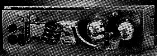
Rear view of the 10 meter amplifier. Connectors grouped at the left are for r.f. input and output, a.c. input, stand-by bias control and high-voltage input. The small connector below and to the right of the 813s is for blower-motor power.
Remove the outer shell of the filament transformer T1. Out two pieces of ½ × ½ inch aluminum angle to a length of 4 inch, and drill holes to match the two holes that go through the bottom edge of the core. Next, drill a No. 25 hole inch from each end of both pieces for mounting. Fasten these mounting strips to the transformer core, using the original bolts.
Place flexible couplings on the shafts of C, and C2, mount the chassis panel on the rails with at least two sheet-metal screws (furnished with the rails) on each side, and one at each end. Before tightening the screws, use a mechanic's or carpenter's square to check the corners- Place extension shafts in the flexible couplings of C, and C2 and then place T1 in position against the front lip of the chassis and between the extension shafts. Check the clearance carefully, then scribe and drill the mounting holes for T1. Place a 1 inch screened vent plug above and to the left of T1, as shown in the photographs. Drill four or five ¼ inch vent holes in the bottom side of the chassis, near the front lip, between RFC, and T1, and five or six directly above the pilot lamp.
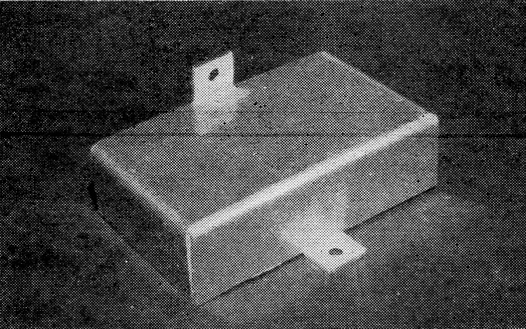
The feedback shield described in the text and Fig. 3. The rear side of the shield is open.
A slight amount of feedback was encountered in the 15 and 20 meter amplifiers. This was eliminated by placing a small shield over the output coax connector and the feed-through insulator connected to C2. The shield is cut from sheet aluminum as shown in Fig. 3, and a photo shows the finished product after bending. Notice the ½ × 1/16 inch notches. These are made to clear the lip of the chasss rail. Use a ¼ inch 6-32 binder-head machine screw through the rail and Tab A, and a ¼ inch No. 6 sheet-metal screw through Tab B into the bottom of the chassis panel. One end of this shield is visible just to the right of the bias transformer in the interior view of the amplifier.
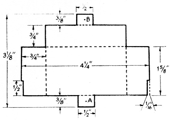
Fig. 3. Sketch showing dimensions of the feedback shield. Bends are made along trie dotted lines. See detail photo.
Support the front panel, face down, an inch or two off the workbench. Insert the extension shafts of C1 and C2 through the front panel holes and carefully center the chassis on the panel as before. Scribe on the panel an easily-seen mark all the way round the chassis. Remove the chassis panel from the rails and carefully reposition the rails inside the scribed mark on the back of the front panel. Holding the rails in position, use a long scriber or pencil to transfer to the panel the two outside holes on the lips of each end piece. Similarly, transfer the second hole from each end on the long side rails, also the eighth hole from the left-hand end of the bottom rail and the ninth hole on the top rail. Prick punch and drill clearance holes for the 2-inch No. 6 sheet-metal screws used to hold the front panel to the chassis. After checking the alignment of these holes, set the front panel aside.
Wiring
Mount a three-terminal ungrounded tie-point strip midway between T1 and R1 and one inch back from the front lip of the chassis. The primary leads from T1 and T2, as well as the leads from J6, will be attached to the center and left-hand terminal. One of the 115 volt a.c. leads from J4 is also attached to the left-hand terminal while the other a.c. lead goes to the right-hand terminal of the tie-point strip. When the front panel is mounted on the chassis, flexible leads will be run from the center and right-hand terminals to the power switch.
The location of most of the remaining components can be determined from the interior-view photo.
Much of the wiring can be done before mounting the P517 panel permanently on the rails. Use No. 12 wire for the filament circuit. Insulated hookup wire may be used for the bias-supply connections. Attach leads to J6 that will reach the tie-point strip near the filament transformer. Use bent solder lugs under the heads of mounting screws of C1 and C2 to hold the wires in place and keep them from contact with high-voltage or r.f. wiring. Attach 5 inch leads of flexible wire to J3 and J4. High-voltage supply leads should be made with high-tension cable, or with rigid wire well spaced from the chassis and other metal. Attach the chassis panel to the rails with at least 12 sheet-metal screws. Complete the wiring and set the chassis aside.
The front panel
The chrome handles at each end of the panel are Bud No. 119168. Mount them 7/8 inch from each end and equidistant from top and bottom. You will find these handles to be the perfect answer for lifting the amplifier in and out of its rack mounting. They will also support the full weight of the amplifier, when you have it face down on your workbench for service, thus protecting the controls.
With the panel face up, locate three holes on a vertical line 2½ inch from the right end as follows: the pilot-lamp hole is 1½ inch down from the top, the hole for the filament switch is 2¾ inch from the top, and a 5/16 inch hole for the shaft of R1 is 1½ inch up from the bottom of the panel. Drill a No. 25 hole 2 inch to the left of the pilot light and 1½ inch down from the top of the panel. Mount a one-terminal ungrounded tie point on the rear of the panel. Mount the meter with its center 3¼ inch from the left-hand end of the panel and 2¼ inch from the top. The s.p.d.t. slide switch, S2, is centered directly below the meter. Place a solder lug on the left-hand mounting screw of S2.
The bracket for R1 is made from a piece of 1/8 × 1 × 2½ inch aluminum or brass. Bend a 1 inch leg for attaching to the chassis and, after drilling two No. 25 holes, mount with the center line of the bracket in line with the 5/16-inch hole in the panel. Leave a 3/8 inch space between the bracket and the panel. Transfer the panel hole to the bracket, drill a 7/16-inch hole and elongate it with a round file to simplify lining up the shaft of Ri in the panel hole.
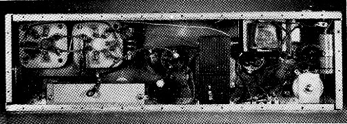
Interior view of the chassis. The bifilar filament choke is below the 813 sockets. The bias-supply transformer is to the right of the filament transformer, suspended from the top of the chassis. The bias-control potentiometer is in the lower right-hand corner.
After placing the 0.01-µf. capacitor across the meter terminals, wire R3 from the positive terminal of M1 to the ground lug on S2, and ground the terminal of S2 closest to the lug. Wire R4 from the negative post of M1 to the center contact of S2. Connect R2 from the positive post of M1 to the other terminal of S2, and run a piece of No. 18 solid insulated hook-up wire from this switch terminal to the tie point near the pilot light.
The 6.3 volt winding on T2 can be used for the pilot light. Pass the center-tap lead from T1 over the top of the extension shaft of C1 before connecting it to the positive post of M1. This will prevent it from coming in contact with the high-voltage lead or the plate choke. Leave enough slack in the leads to the pilot light, power switch and bias supply, so that the front panel can be easily lifted on or off the shafts of C1, C2 and R1.
After soldering these leads, position the front panel and insert the ten No. 6 ½ inch self-tapping metal screws. Position a piece of ¼ inch tubing from the bottom of the 500 pF blocking capacitor, around the nearest 813 to a stator terminal of C1. The mounting of L1 will depend upon the size of the coil which, of course, will vary with the frequency for which the amplifier is being built. The rear-view photo shows the 10 meter amplifier with one end of L1 attached to C1 and the other end supported by a stand off insulator. Bud heat-dissipating plate caps are used on the 813s. Copper strap, % inch wide, is used to connect the tube caps to RFC3.
Use "Tekni-Cals" for lettering. After they are thoroughly dry, use a small camel's-hair brush and flow on lacquer thinner very sparingly. Practice this step on an old panel before attempting to do your finished amplifier panel. When properly done, your lettering will have a decidedly professional appearance.
Shielding
The shielding enclosure is made of sections of perforated aluminum sheet supported on a framework of ½ × ½ inch aluminum angle stock. The front edges of the shield overlap the chassis on top, bottom and the left-hand side. The right-hand end of the enclosure is fastened to the angle piece attached to the chassis panel.
You can order 0.051 inch perforated aluminum sheet and ¼ × ¼ inch angle stock for the shielding enclosure precut to exact size from Dick's, 62 Cherry Ave., Tiffin, Ohio. Of the perforated sheet, you will need two pieces 11 by 14 inch, one piece 4¾ by 11 inch, one piece 4¾ by 10½ inch, and one piece 4¾ by 14 inch. In the angle stock, you will need four pieces 10½ inch long, two pieces 14 inch, three pieces 5 inch and two pieces 4 inch long. (Order one piece 31½, one piece 28, and one piece 33½ inch long.) The total cost of the perforated sheet is $4.27, and the angle is $1.40, plus postage. Use ¼ inch No. 6 sheet-metal screws for assembly and space them approximately 2 inch all around. The ventilating fan is obtainable from Allied Radio (Cat. No. 72P715). It is mounted against the inside of the rear wall of the shielding enclosure with the axis of the fan exactly opposite the plate caps of the 813s. Before attaching the top of the enclosure, run the a.c. leads from the fan motor along the bottom to the 2-prong Jones socket, J.Adjustment
Check out the bias voltage and filament circuit before applying high voltage. A variable h.v. power supply is definitely recommended. If not available, arrange to insert a 100 watt lamp in series with the primary of the plate transformer while testing. A power supply delivering from 1800 to 2250 volt d.c. at 400 to 500 mA is ideal. Before applying high voltage, connect a dummy load to J2. With a plate voltage of 2000 volt, S2 in the PLATE position, and the terminals of J3 shorted, adjust R1 for 40 mA of plate current. With carrier injected in the s.s.b. exciter and S2 in the GRID position, adjust the exciter loading for a full-scale reading on M1.
Turn S2 to PLATE, C2 to maximum, and adjust C1 for minimum plate current. With reduced plate voltage, decrease the capacitance of C2 for 200 mA of plate current, maintaining resonance with C1. With plate voltage increased to 2000, adjust C1 and C2 for approximately 400 mA. Grid current should be 100 mA.
With the exciter adjusted for normal s.s.h. r.f. output, the linear amplifier, with voice, should swing to approximately 150 mA of plate current. A steady whistle will increase the plate current to 400 mA. The output should be checked for linearity with an oscilloscope during initial adjustment and at regular intervals thereafter.
For c.w. operation, use the same procedure as for s.s.b. operation, adjusting R1 for approximately zero plate current and the exciter for 100 mA of grid current without plate voltage on the amplifier. Load the amplifier to 175 mA with reduced plate voltage and then to 350 mA with a full plate voltage of 2000.
Exciter matching
Most exciters presently in use have enough range in output impedance to provide a match to the cathode circuit of the 813s. This impedance runs from a nominal 140 to slightly more than 200 ohms, depending upon the frequency. In the event that your exciter output impedance is fixed at 50 or 70 ohm, it may not be possible to obtain sufficient drive for the 813s. In such a case, a pi-network such as shown in Fig. 4 may be used for matching. In this particular instance, the relative values of C1 and C2 near the correct-adjustment condition are such that the output capacitor, C2, has a greater effect on tuning than Cu. Therefore, the input capacitor, C1, rather than the output capacitor, C2, is used as the "loading" control.
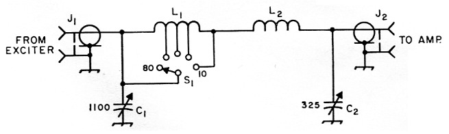
Fig. 4. Pi network for coupling fixed-impedance exciters to the grounded-grid amplifiers. Capacitances are in pF.
| C1 | Miniature triple-section variable, 365 pF per section, sections in parallel. |
| C2 | Miniature receiving-type variable (Hammarlund MC-325-M). |
| J1,J2 | Chassis-mounting coaxial receptacle (SO-239). |
| L1 | l7 turns No. 16, 1¼ inch diam., 2 inch long, tapped at 10, 4 and 2 turn from 10 meter end. |
| L2 | 4 turns No. 12, 1 inch diam., 1 inch long. |
| S1 | Single-pole 5 position ceramic rotary switch. |
The components can be mounted in a Bud CU-2107A 4 × 5 × 6 inch Minibox. Use SO-239 coax connectors for input and output. A piece of RG58/U coax cable should be used between the exciter and matching network and a piece of RG59/U between the network and amplifier will be slightly more suitable than RG-58/U if you happen to have some. Use No. 12 tinned wire for all connections, and keep leads as short and direct as possible.
High-voltage switching
Should you desire to operate two or more of these linears from the same high-voltage power supply, you can avoid the use of expensive high-voltage relays, and their associated wiring, by tying the h.v. terminals of all your amplifiers to the power-supply output. Merely turn on the filaments of the amplifier you desire to use and you are ready to transmit.
The operating-position photo shows the 28, 21 and 14 Mc amplifiers mounted in the author's home-built table rack. Antenna switching is done with the switches on the left while the amplifier selector switch is at the right, below the plate-supply voltmeter.
I would like to express my appreciation for the technical advice of George Stinson, W9KDK. His analysis of the problems encountered, and the suggestions he made contributed immeasurably to the design and construction of these amplifiers.
Build one of these lineare for your favorite band. It will give you hours of operating pleasure and "more watts per dollar."
Larry Kleber, K9LKA.