Thoughts on keying filters
Click-free keying without vacuum tubes.
Everyone knows what key clicks sound like, and generating them yourself is one way to ruin your reputation with friends and neighbors. Excellent past articles in QST have discussed how to check a transmitter for clicks and how to suppress them.(1-5) When the transmitter is cathode- or plate-keyed, a useful suppression device is a keying or lag filter. Most of the available information on keying filters is only qualitative, however, and the usual filter circuits have some disadvantages. This article describes a better keying filter and formulas for its design.
Click suppression
Clicks are generated by any transmitter whose carrier amplitude rises or decays too rapidly.(6) To suppress the clicks, a keying scheme must be used that prevents too fast a transition from "off" to "on" and back again. The modern approach to cathode keying is a separate keyer tube, keyed in its grid circuit. But it seems unwise to use a tube for a job that can be done as well with a simple inductor and capacitor. The preference for keyer tubes may have grown for the following reasons:
Consider the typical filter shown in Fig. 1A (where CK, the cathode bypass capacitor, is not large enough to be considered part of the filter). The equivalent circuit is shown in Fig. 1B. This equivalence is only approximate, because neither the voltage E nor the resistance Ro is strictly constant, but their variation makes no great difference. The object, of course, is to force the battery (cathode) current to rise slowly when the key is closed and decay slowly when the key is opened. The filter does control the current in this way, but not without fireworks at the key.
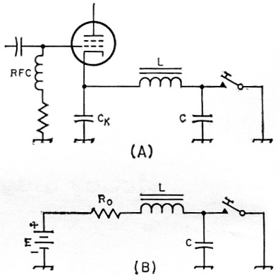
Fig. 1. (A) A conventional L-C arrangement for suppressing key clicks in a cathode-keyed stage.
(B) An approximate electrical equivalent of A.
Cause of arcing
To begin with, suppose that C is omitted. When the key is closed, the initial current is zero. The inductance L prevents the current from increasing abruptly, and the res _it is a gradual increase in current, the rate of rise depending on the ratio of Ro to L. When the key is opened, however, the initial effect of L is to maintain the current at its maximum. The contact voltage rises abruptly to a value that may greatly exceed E, and the result is a soft, persistent arc at the key.
If we include C, we can eliminate the arc. Now as the key is opened, the inductor current charges C, and the voltage across C rises slowly toward the value E. But when the key is closed again, it must discharge C before current can begin in L. Typically, E can be 70 volt and C several microfarad, producing a fat, noisy spark at the contacts. (This may partly explain the onetime popularity of keys with contacts the size of aspirin tablets.) A resistor in series with either the key or the capacitor will reduce the spark but will not eliminate it. Hence, the dilemma. One way of arranging the circuit treats the key contacts badly on make, the other way on break, and worn key or relay contacts are certain trouble.
Reducing the spark
Now look at Fig. 2. The rectifier makes it possible to switch C automatically to the part of the circuit where it will do the most good. Initially, C is charged to the voltage of the open cathode with the polarity shown. When the key is closed, CR prevents the discharge of C through the contacts, the inductor current rises gradually, and C discharges slowly through R and L. When the key is opened, the voltage across the contacts rises gradually as the inductor current charges C through CR. The result is essentially no arc, no spark.
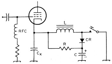
Fig. 2. A diode and resistor connected as shown will minimize sparking at the key contacts, as described in the text. See text for suggested component values and ratings.
Design
If the filter of Fig. 2 is critically damped for both make and break, the cathode current will rise and fall exponentially as shown in Fig. 3. There are two possible sets of LC values for critical damping, but the more useful set is the one that specifies the smaller inductor.
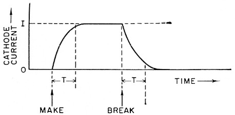
Fig. 3. Typical keying wave shape.
The first step is to calculate
![]()
where E is the key-up potential of the cathode in volts, and I is the key-down cathode current in amperes. Now, if T is the lag time in seconds for the current to reach 95 per cent of its maximum on make, and 5 per cent of its maximum on break, then
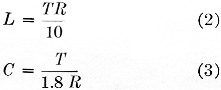
where L is in henrys and C is in farads.
What value for T? This will depend partly on your taste; some people like softer keying than others. A rise (and decay) time of 14 milliseconds (0.014 second) should permit keying at up to 40 words per minute without trouble from overly soft dots. For softer keying, the value chosen for T should be increased accordingly. The values of L and C given by formulas (2) and (3) are not especially critical. It is best to maintain the ratio of L/C that follows from the formulas, but a change in either inductance or capacitance by 20 or 30 per cent from the calculated value will not affect the keying wave-form very much.
Example: I am keying a 6L6 buffer, and I find that the key-up cathode potential is 60 volt, the key-down cathode current 50 milliamperes. A lag time of 20 millisecond is fast enough for my sending. Then,
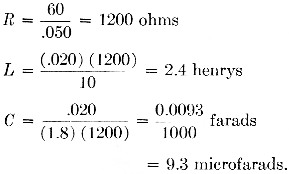
I find that I have a 2 henry, 200 milliampere filter choke and an 8 microfarad, 250 volt electrolytic capacitor on hand. These are close enough to do nicely.
Ordinary filter chokes work well in this circuit. The choke should be large enough to maintain most of its rated inductance while passing the direct cathode current. If the keyed current is large, so that the inductance calculated from (2) turns out to be inconveniently small, then there is no harm in paralleling two or more chokes to obtain a smaller inductance. Capacitor C must be rated to withstand the key-up cathode voltage. Either paper or electrolytic capacitors will do.(7) Rectifier CR must have a peak-inversevoltage rating that equals or exceeds the cathode voltage. The average current rating need not be large, because the rectifier passes current only when C is being charged and consequently dissipates little power. Small silicon or germanium power rectifiers are adequate in most cases.
Notes
- Goodman, "Some thoughts on keying," QST, April, 1941, p. 17.
- Goodman, "Keying the crystal oscillator," QST, May. 1941, p. 10.
- Goodman, "Tube keying," QST, June, 1941, p. 31.
- Goodman, "Key clicks and receiver bandwidths," QST, April, 1950, p. 34.
- Gooiman, "Keying the Radiotelegraph Transmitter," QST, July, 1956, p. 27.
- Occasional pathological causes are incomplete neutralization and parasitic oscillations, but these ought to be fixed anyway. See the listed references.
- In some instances where the amplifier is operating without fixed bias, the leakage through an electrolytic capacitor may be sufficient to produce a back wave with the key open - Ed.
G. Franklin Montgomery, W3FQB.