The simplicity modulator
The modulator shown in Fig. 1 is an inexpenlive means of converting a c.w. transmitter to n i vpe of carrier-control a.m. transmitter. The system incorporates ease of adjustment, simplicity , and versatility, while providing an effect sir filar to carrier-control systems using only one tithe and one adjustment. Operation is practically foolproof and it can be applied to practically any transmitter.
The c.w. transmitter need only meet the following requirements: Tetrode or pentode final amplifier, and separate oscillator and final with adequate isolation (to reduce frequency shift). Some transmitters use a single tube for an oscillator and final, and these must be changed to incorporate a separate oscillator before the modulator can be used.
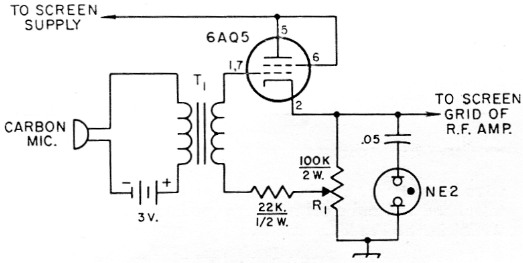
Fig. 1. The Simplicity Modulator. Capacitances are in µF resistances are in ohm.
R1 100 kΩ 2 watt variable resistor. T1 Carbon mike-to-grid transformer (Triad A-1X).
The audio amplifier used to drive this modulator is not required to furnish much power. Practically any audio amplifier, such as one salvaged from an old radio, TV or phonograph, will work. With a carbon mike, only one stage of amplification is needed.
To adjust the simplicity modulator, load the transmitter for maximum c.w. output. Record the plate current reading and divide this value by 2. Connect the output of the modulator to the screen grid of the r.f. amplifier tube. Apply high-voltage power and adjust the variable resistor R1 until the transmitter plate current is the value of the original plate current divided by 2. The plate current should increase with modulation and the neon modulation indicator should flash on modulation peaks.
Have a friend check the sound of the modulation or use a scope to adjust the audio amplifier for the best audio level. It may be necessary to lower the transmitter plate current another 10 or 15 ma. to obtain better audio quality. Power for the modulator may be obtained from the original screen supply, providing there is not too much variation in voltage with modulation. This system is not difficult to use, but some experimentation may be necessary. The screen bypass capacitor of the r.f. amplifier tube should be about 0.002 tsf.
If a carbon mike is used, it would be best to employ a d.p.s.t. switch to connect the mike circuit and to key a relay which would turn on the high-voltage power. If a heavy switch is used to do this, the relay may be unnecessary. If a push-to-talk mike is used, a relay must be keyed by the mike switch to turn on the high-voltage poser.
John Solman.