The CWX
An analog of VOX for the C.W. mode.
A convenience that is frequently available with single-sideband transmitters is VOX (voice semibreak-in) control of the station operation. A closely-parallel control circuit, CWX, has been designed that provides similr automatic semi-break-in control for c.w. operation. The principle involved is also essentially the same as that of two "turner-onner" devices described in earlier issues of QST.(1)
Circuit
The circuit of the CWX is shown in Fig. 1. The operation of this circuit is as follows: When the key is open, both triode stages are biased so that none of the relays is energized. At the instant the key is closed, keying relay K1 is energized with an overdriving current. Simultaneously, the closing of contacts K1A grounds the grid of V1B, causing K2 to be energized (also with an over-driving current). K2 switches line voltage to the antenna changeover relay K3, and simultaneously turns on an "on-the-air" sign.
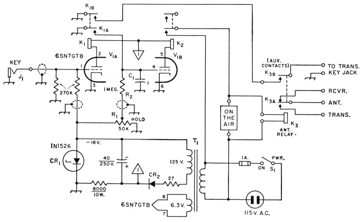
Fig. 1-Circuit of the CWX control unit. Resistances are in ohms (K= 1000). Resistors are 1-watt, unless indicated otherwise. Capacitances are microfarads (pf).
C1 1 pF Mylar.
C2 40 µF 250-volt electrolytic.
CR1 18 volt 10 mA 1 watt Zener diode (International Rectifier).
J1 Open-circuit key jack.
K1 D.p.d.t. relay, 10,000-ohm 5-mA coil (Potter R Brumfield KCPI 1 ), or similar relay with three poles (KCP14); see text.
K2 Same as K1, 2 poles (see text regarding use of second pole).
K3 Coaxial antenna relay with external auxiliary contacts (Dow-Key DK60-G2C, 115-volt a.c. coil).
R1 Linear-taper control.
R2 1 megohm, 1 watt.
S1 S.p.s.t. switch, any type.
T1 Power transformer: 125 volts, 50 mA; 6.3 volts, 0.6 amp. (Stancor PA-8421, 2-amp. filament winding not used).
The transmitter is then keyed in the normal manner through contacts Kls. K2 will not open with normal character spacing because cutoff of Vls is delayed by the time constant of C1 and R2. However, if there is a pause in keying, the grid voltage of VIII will rise from ground potential exponentially (because C1 must be charged through R2), and will eventually reach the value set by potentiometer R1. R1 thus sets the "hold" time of K2. With the constants shown in Fig. 1, R1 has a hold-time range from about ½ second to 4 seconds. It is suggested that the hold time be adjusted to about 1 second.
Now, if the operator sends a letter T, K1 will follow the key, but K2 will remain in the energized (transmit) condition for the duration of the hold time, after the character has been completed. If a string of characters is sent, the CWX will change from the receive to the transmit mode at the instant that the first character is started, and it will remain (hold) in the transmit mode until a space between keyed characters, equal to or greater than the hold time, first appears. Whenever the next string of characters begins, the CWX will repeat the above action. If the operator wishes to listen, he need only pause for the hold time, at the end of which K2 will return the station to the receive mode. Thus the transmitting key itself controls the entire station, switching it between receive and transmit conditions in a manner exactly analogous to the automatic switching provided by the signal from a microphone by means of a VOX circuit.
Interlock
A unique feature of the CWX is an interlock to ensure that the antenna change-over relay has arrived at the transmit position before any r.f. comes out of the transmitter. The interlock is obtained by wiring a normally-open pair of external auxiliary contacts on the antenna relay in series with contacts Kw of the keying relay. Thus, even though contacts K1B may be closed, the transmitter will not be keyed until contacts K311 are closed. The desired interlock action is achieved by proper adjustment of the auxiliary contacts K3s. These contacts must be adjusted so that they close later than the internal contacts K3A when K3 is energized.
It will be noticed that one key terminal is at ground potential, while the other terminal is always at low voltage with respect to ground. The current that must be handled by the key contacts is well under 100 µs.
Construction
The components of the CWX can be housed in a 10 × 4 × 2½ inch aluminum box or chassis. Shielded wire should be used for all connections to grids, as indicated in Fig. 1. Otherwise, there is nothing critical about the wiring or placement of components. It is not necessary to provide a heat sink for the Zener diode. Either screw terminals, or phono jacks and plugs can be used for external connections.
Testing
The keying relay must follow the key, whatever type it may be - straight key, bug or electronic key. To check this, connect an ohmmeter across the terminals of the key before it is plugged into the CWX. Send a string of dots, and then a string of dashes, and observe the ohmmeter reading for each string. With typical adjustment of a bug or a keyer, the ohmmeter will hover, respectively, at about 50 and 75 per cent of the short-circuit reading. Now connect the key to the CWX and connect the ohmmeter to the output keying terminals. Again send a string of dots, and a string of dashes. If the ohmmeter readings are the same as before, relay K1 is following the key.
When the first keyed letter that switches the CWX from the receive to the transmit mode begins with a dot, it is necessary that the dot be heavy enough so that the external auxiliary contacts of K3 close during the dot. If this is not the case, a keyed letter L would be transmitted as a D, for example. All dots from an electronic key have the same weight and, with normal adjustment, this error will not occur up to fast keying speeds. However, the absence of this error, for the chosen weight and speed, should be verified by test with a monitor. Since the heaviness of dote is less reproducible with a manual key, one cannot be certain that a beginning dot of a first letter will be transmitted. For this reason, when a manual key is used, the CWX should be switched from the receive to the transmit mode by starting each sequence with a letter T, or a BK. It should be pointed out that this malfunction may occur with any relay-operated automatic control system, including VOX. It is not unique to the CWX.
Optional Modifications
If an electronic keyer is being used, rather than a straight key or bug, VIA and K1 may duplicate a portion of the keyer. If an extra normally-open contact pair is available on the keying relay of the keyer, then it will not be necessary to build the V1_.-K1 circuit in constructing a CWX unit; it will be necessary to build only the V1B-K2 circuit.
If desirable, the final amplifier of the transmitter could be blocked off during receive pe iods by applying cutoff bias voltage by means of the spare contacts of K2. Alternatively, these contacts could be used to mute the receiver.
If side-tone keying is desired, it could be accomplished by substituting a 3-pole relay at K1. The same type of relay suggested under Fig. 1 is obtainable with 3 poles, although its maximum operating speed may not be as high as the twopole model.
Notes
- Hiehle, "An Automatic Transmitter Turner-Onner," QST, May, 1950.
Campbell. "Tattoo - Automatic C.W. Transmitter Control," QST, August, 1956.
Dale J. Fischer, W4VQK.