Practical Tripler Circuits
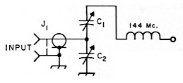
A simple model of a varactor frequency doubler, such as Fig. 1A, requires an input circuit to tune the varactor to the input frequency while rejecting all others, and a tuned output circuit which passes the wanted second harmonic while rejecting any others. To make this simple doubler into a tripler, the output circuit is tuned to the third harmonic, and an idler circuit (shown enclosed by dotted lines in Fig. 1A) tuned to the second harmonic is connected across the varactor to improve the efficiency. In early experiments with varactor frequency multipliers, no idler tank was used and the efficiencies obtained were none too good. The idlers had to await theoretical proof - idlers were first considered a sort of black magic - before they became an accepted way to reinforce the harmonic output of a varactor multiplier.
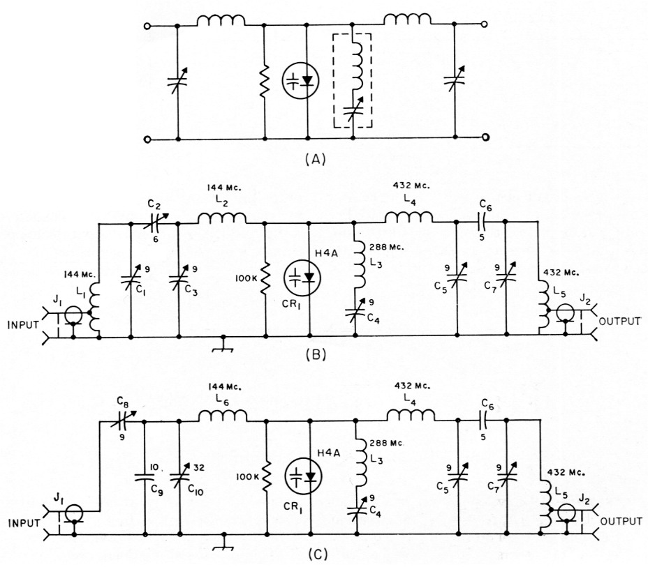
Fig. 1. (A) Model varactor multiplier circuit. (B) Practical tripler circuit using the Amperex H4A varactor and lumpedconstant circuits. (C) Improved tripler circuit using a capacitive-divider input circuit.
| C1,C3,C4,C5,C7 | 9 pF piston trimmer (see text). |
| C2 | 6 pF trimmer (Johnson 189-2). |
| C6,C9 | Silver mica capacitors. |
| C8 | 9 pF variable (Johnson 160-104). |
| C10 | 32 pF variable (Johnson 160-130). |
| CR1 | Amperex H4A varactor diode (1N4885). |
| J1,J2 | BNC coaxial receptacle, chassis-mounting. |
| L1 | 9 turns No. 18, 3/8-inch diam., ½ inch long; tap at 2 turns from the ground end. |
| L2 | 7 turns No. 18, 3/8-inch diam., ½ inch long. |
| L3 | 4 turns No. 18, ¼-inch diam., ¼ inch long. |
| L4 | 2 turns No. 18, ¼-inch diam., ¼ inch long. |
| L5 | 3 turns No. 18, ¼-inch diam.; tap 1 t. from gnd. end. |
| L6 | 6 turns No. 16, ½-inch diam., ½ inch long. |
High orders of multiplication can be obtained with single varactors, but the circuits become rather complex because of the number of idler circuits required. Also, each idler tank restricts the bandwidth of the multiplier which is an undesirable feature. A varactor device requires moderate bandwidth to work properly, because of characteristics inherent in the operation of a nonlinear reactance and because of variations in the way a practical varactor's capacitance changes.
For a "starter" circuit to construct, we need only to add input and output tuned circuits to the circuit in Fig. 1A for matching to and from 50 ohms, as in Fig. 1B. This circuit was constructed for 432 Mc. as shown in Fig. 2, using a 4 × 2 × 1½-inch Minibox with BNC-type connectors at either end for input and output. The phono type connectors so popular on h.f. transmitters should not be used. Two 54-inch cone ceramic insulators are used to support the junctions of C3-L2 and L4-05. All the glass trimmers are surplus items available from Barry Electronics; these trimmers were found to be superior mechanically to the TV-type ceramic trimmers. The varactor, an Amperex 1N4885 (H4A), is bolted directly to the Minibox, providing an easy heat sink.
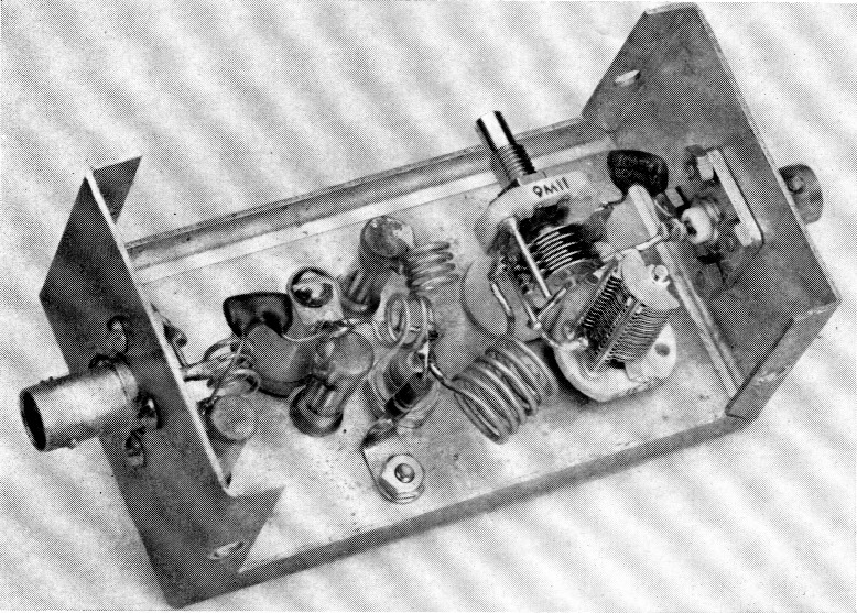
Fig. 2. Varactor tripler using the circuit shown in Fig. 1 B.
This first model was working only after several hours of experimenting with the input circuit. Using double-tuned circuits for impedance matching is no easy job. With C1, C2 and C3 all variable, getting a 50-ohm input impedance for the exciter to "look at" while at the same time delivering maximum power to the varactor was about impossible. A varactor's impedance changes with voltage across it, which makes things no easier. In the end, to make the unit easier to adjust, the input circuit was modified.
The input circuit suggested by Amperex in their application notes on the H4A(1) was installed. See Fig. 1C for the changes. The capacitive-divider input circuit made input matching easier. This circuit does not have the selectivity of the double-tuned circuit used before, but this should not be a problem since a "clean" 2-meter exciter should be used. If your 2-meter rig has harmonic or spurious output, it is the exciter you should work on and not the multiplier input circuit.
The final version of the multiplier, using the circuit of Fig. 1C, is shown in Fig. 3. This little box will deliver about 10-12 watts on 432 when driven with 20 watts on 144 Mc. - enough to drive the popular amplifiers using the 4X150 series tubes. If this multiplier were to be used directly into an antenna, a strip-line filter(2) or the transmatch described in this article should be used to reduce the unwanted harmonics to an acceptable level. When the multiplier is used to drive an amplifier, a tuned grid circuit should give sufficient harmonic attenuation to prevent trouble. The important thing to remember is that a varactor does produce harmonics other than the one you wish, although usually they are far enough away from the wanted harmonic so they don't cause too much trouble, if selective coupling circuits are used.
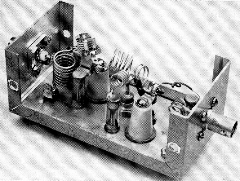
Fig. 3. The tripler with modified input circuit. The input tuning capacitor is mounted on top of the ceramic standoff insulator. A hole was drilled in the bottom half of the Minibox to allow adjustment of this capacitor.
Line Circuits
In an attempt to make a higher-efficiency varactor multiplier, W10ER used a 3 -wavelength strip line in the output tank. The use of a strip line will also give additional attenuation of unwanted harmonics. This circuit is given in Fig. 4, again using capacitive-divider input, and the completed multiplier is shown in Fig. 5.
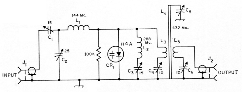
Fig. 4. W1CER's varactor tripler. A strip-line output circuit is used for better attenuation of unwanted harmonics than is possible with lumped-constant circuits.
| C1 | 15 pF variable (Hammarlund.MAPC-15). |
| C2 | 25 pF variable (Hammarlund MAPC-25). |
| C3 | 15 pF variable (Johnson 160-107). |
| C4,C6 | 10 pF ceramic trimmer (Centralab 829-10). |
| Cs | See text. |
| J1,J2 | BNC coaxial receptacle, chassis-mounting. |
| L1 | 6 turns No. 16, 3/16-inch diem., ½ inch long. |
| L2 | 3 turns No. 12, 3/16-inch diem., ¾ inch long. |
| L3,L4,L5 | See Fig. 6. |
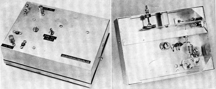
Fig. 5. W1CER's varactor tripler. In the panel view, the input tuning adjustments are located at the lower left,the idler adjustment is at the center, and the output link adjustments are at the upper left. In the bottom view the input circuit is at the lower right and the varactor with its biasing resistor is at the center. The strip-line tank circuit in the trough is tuned by a homemade capacitor described in the text.
W1CER used a 5 × 7 × 2-inch chassis, although the unit can be made to fit in a 4 × 5 × 2-inch base if compactness is desired. A shield is formed to fit the length of the chassis 2 inches from one wall, forming a 2-inch-square trough inside the chassis. A National TPB polystyrene feedthrough connects the varactor to L3.
Fig. 6 details the layout of the strip-line tank circuit, which uses a 5-inch brass strip % inch wide, having a M-inch "foot" at the bottom for bolting the strip to the chassis. The input and output links are tuned with TV-type ceramic trimmers. The low-potential ends of L3 and L5 are soldered directly to the tops of these trimmers. C5 is made by cutting two 1-inch disks from sheet brass. One disk is soldered to the end of L4, and a mount for the other disk is fashioned from a Miller 4400 coil form. The ceramic form itself is broken off from the mount, and the slug removed from the end of the threaded rod. The disk is then soldered to the end of the rod. The coil-, form base is mounted on the chassis so that the two disks are opposite each other (see Fig. 6).
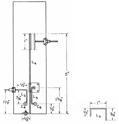
Fig. 6. 432-Mc. tank-circuit details for W1CER's varactor tripler. L3 and L5 are coupling loops made from No. 14 wire, and L4 is a 1/2-inch wide brass strip cut from sheet stock.
For better mechanical stability of the tuning shaft, a 6-32 nut can be placed on the shaft so it may be locked in place.
Tuning Up
A varactor multiplier is simple to tune, provided you have the proper test equipment. But test equipment for 432 Mc. is not easy to come by. Most constructors will find they have to spend more time making test gear to check the varactor than in building the multiplier itself. Fig. 7 shows two possible test setups for checking a multiplier unit. The first requires a nonreactive 50-ohm dummy load, and the second uses a trans-match with a 300-ohm load. Most of the dummy loads available to amateurs are too reactive at 432 to be any good. The constructor may make his own 50-ohm load from 100 feet of RG-58/U coax. This length of coax, terminated with a 50-ohm, 2-watt composition resistor, will provide a nonreactive load that will handle the power from one of the varactor multipliers described above - and give the builder a good lesson in the losses of coax lines!(3)
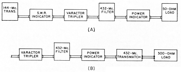
Fig. 7. Testsetups for checking varactor multipliers. A uses a 50-ohm load while B has a transmatch and 300-ohm load.
Another approach is to make a dummy load from carbon resistors(4) and use a transmatch to tune out any reactance in the load. This resonant load, when used with an s.w.r. indicator, will give a check on the harmonic content of the varactor's output. (More about this later.) When the varactor multiplier is working, the transmatch can be used in the station to match Twin-Lead feeders. The 432-Me. transmatch circuit is shown in Fig. 8. It is constructed from a 4½ × 7¾-inch piece of sheet copper, with a 1½-inch lip bent on either end. Two hairpin loops are used for L1 and L2. L2 is supported by a %-inch standoff insulator. A crystal socket is used as an output connector as it has the proper pin size and spacing for the popular Twin-Lead connectors. The taps given in Fig. 8 for L2 should be good for any low-reactance 300-ohm load. Other impedances will require changing the position of the taps.
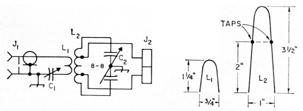
Fig. 8. 432-Mc. transmatch constructed by W1CER.
In either test setup, a filter is used to insure that the output you are measuring is 432-Mc. energy and not some other harmonic. A simple strip-line filter like the unit described in The Radio Amateur's V .H.F. Manual (p. 304) will do the job. A power indicator is the hardest item of all to come up with. Bird wattmeters are very expensive; it may, however, be possible to borrow one from a local business-radio repairman. Several models of Micromatch-type bridges that work on 432 are available on the surplus market. One of these units is a good investment for anyone seriously interested in 432 work. If you are not able to get a wattmeter, a simple relative indicator such as a wavemeter can be used at the load.
When the author was testing one of the multipliers described above, a Monimatch that worked well on 144 Mc. was tried as an output indicator for 432. It worked, but there was a 3-db. loss of power in the Monimatch, so it was quickly removed.
The s.w.r. bridge between the 144-Mc. exciter and the varactor multiplier indicates when the varactor input circuit is properly tuned. The input circuit of any of the varactor multipliers should be adjusted for a minimum s.w.r. reading. Then adjust the idler and output circuits for maximum output on 432 Mc. As the second-harmonic frequency is approached, the idler adjustment will make the output jump up.
The tuning adjustments will vary with changes in the drive level. First adjustments should be made with 10 or 15 watts from the exciter. After all the tuned circuits are adjusted correctly at this power level, the drive may be increased to about 30 watts for the H4A. With higher-power varactors, higher drive levels can be used. For any drive level, the varactor circuits should be tuned for best power output. W1CER's multiplier delivered a measured output of about 14 watts when driven with 20 watts on 144 Mc.
If you are using the 432-Mc. transmatch, you can get a check on the harmonic output by adjusting the transmatch for a 1:1 s.w.r. between the multiplier and transmatch. Then remove the strip-line filter and recheck the s.w.r. If the s.w.r. has gone up, you can be sure some harmonic energy is getting out. Often these harmonics will not cause any trouble even when the multiplier is used directly into the antenna, but remember that if they are there you will never see a 1:1 match to your antenna.
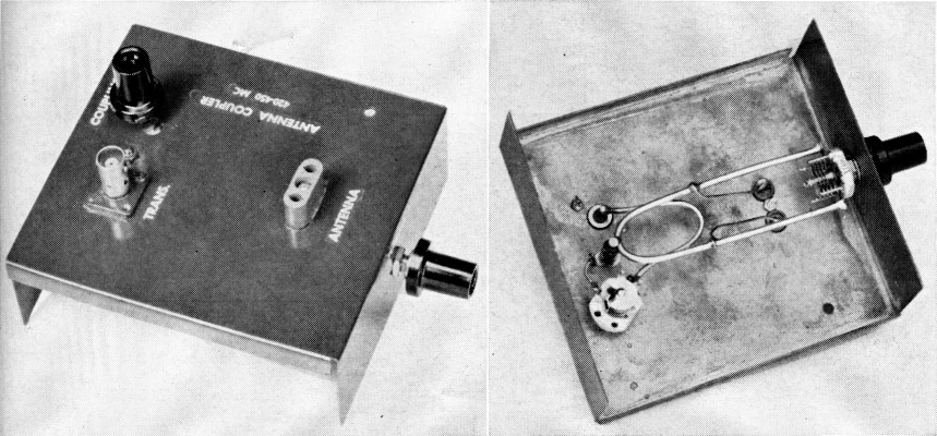
Fig. 9. Top and bottom views of the 432-Mc. transmatch. The chassis is homemade, although a Minibox could be used.
- "Designing Frequency Multipliers with Varactor Diodes," Report S-121, available from Amperex Electronics Corporation, Hicksville, L. I., N. Y.
- Strip-line filters for 50-432 Mc. are described in The Radio Amateur's V.H.F. Manual, Chapter 12.
- See Chapter 11, page 290, of The Radio Amateur's V.H.F. Manual.
- Ibid., page 291.
Douglas A. Blakeslee, W1KLK.
Corrections
Change the input circuit (Fig. 1C and Fig. 4) to the following: