A wide-range voltage-regulated power supply
Versatile Unit for Tube or Transistor Circuits
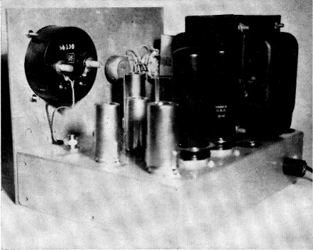
Interior view showing arrangement of components on the top side of the chassis. Along the rear edge of the chassis, from left to right, are the 12AX7A, and 6L6s (subsequently changed to 6L6GCs, because of their higher ratings), and the power transformer. Inboard are the 5651, 6AU6A and the 0A2s. The screwdriver shaft of R7 is below the meter. The shaft of R5 is hidden behind the 5651.
Anyone who does much building and experimenting, as I do soon learns the value of a regulated power supply whose output voltage is capable of adjustment. Not only is it a time-consuming nuisance to try to obtain a desired voltage from a fixed-voltage source through the right combination of voltage-dropping or voltage-divider resistors, but any appreciable change in load current will usually change the voltage drastically. With a regulated supply, you simply set the voltage to the desired value without load, and have the satisfaction of knowing that connection of the load and variations in load current, as you adjust the equipment you are working on, will cause virtually no change in the preset voltage. After struggling along for some time without such a supply I decided to take time out and build the one whose circuit is shown in Fig. 1.
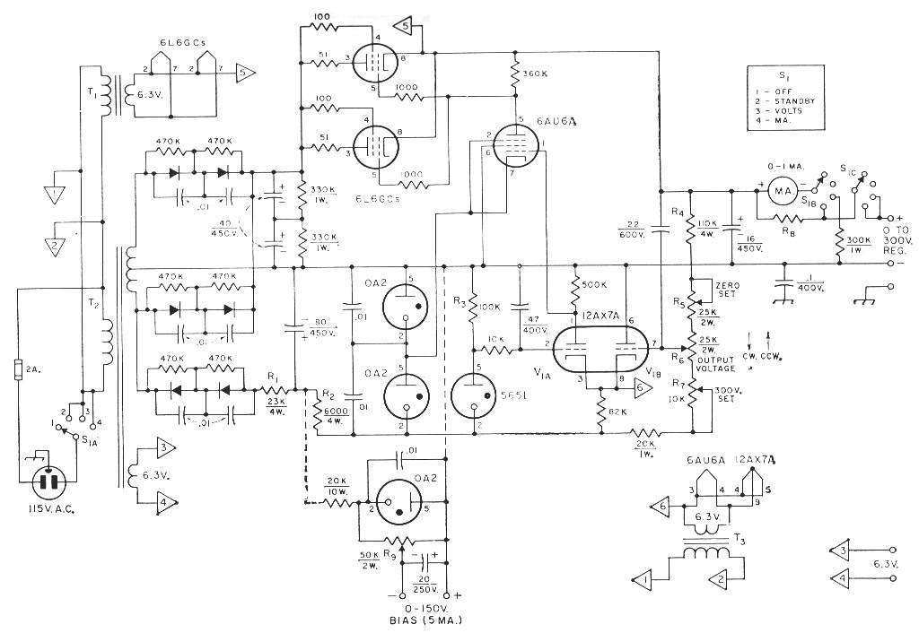
Fig. 1. Circuit of the variable-voltage regulated power supply. Capacitances are in µF; resistances are in ohms (k = 1000). Polarity marks indicate electrolytic; other capacitors are paper or disk ceramic. Fixed resistors are ½-watt unless indicated otherwise. All diodes are 800 p.i.v., 750 mA. (Sarkes Tarzian F8).
| R1 | Two 47,000-ohm 2-watt resistors in parallel. |
| R2 | Two 1 2,000-ohm 2-watt resistors in parallel. |
| R3 | See text. |
| R4 | Two 220,000-ohm 2-watt resistors in parallel. |
| R5,R6,R7,R9 | Linear control. |
| R8 | 300-times shunt for 1-ma. meter. |
| S1 | 3-pole single-section 5-position nonshorting ceramic rotary switch (Centralab PA-2007, 4 positions used). |
| T1 | 6.3-volt 2 A (min.) filament transformer. |
| T2 | 800 volts, c.t., 200 mA; 6.3 volts, 5 A. (Thordarson 24R07U, 5-volt winding not used). |
| T3 | 6.3 volt 1.2-amp. filament transformer. |
Circuit
Basically, the circuit consists of a pair of 6L6GCs acting as a variable-resistance element in series with the load, a 12AX7A which senses any change in output voltage with reference to the fixed voltage drop across the 5651 regulator tube, and a 6AU6A which amplifies the change and applies it as a change in bias to the 6L6GCs. The change in bias is applied in such phase as to alter the plate-cathode resistance of the 6L6GCs in the direction required to restore the output voltage to its original value.
This supply will maintain regulation with load currents up to the maximum current rating of the 6L6GCs (approximately 150 ma. for the pair) at output voltages up to 300. The output voltage may be set to the desired value by adjustment of R6. Unlike some regulated supplies, the output voltage of this one can be brought down to zero. Thus, it is adaptable to transistor circuits as well as tube circuits. To provide for this reduction in voltage, the regulating control circuit is based on a potential negative with respect to output negative. R5 is used to bring the output voltage down to zero with R6 in its most-counterclockwise position, while R7 is used to limit the output voltage to 300 with R6 in its most-clockwise position. These two adjustments are not entirely independent, so some juggling of the adjustments of R5 and R7 will be necessary to arrive at the desired condition.
A maximum current of 150 ma. may be drawn from the supply, without exceeding the 6L6GC ratings, at voltages down to 150. To stay within the dissipation rating (60 watts per pair), the maximum current should be scaled down, as the output voltage is reduced, to approximately 135 ma. at 100 volts, 120 ma. at 50 volts, and 100 ma. at voltages of 10 or less. For most low-voltage applications, this limitation will be of little consequence.
The meter may be switched to read either load current, or output voltage. For convenfence, the meter switch and power switch are combined in S1.
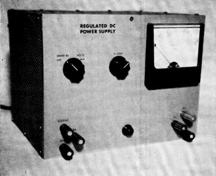
The output voltage of this electronicaliy-regulated power supply is adjustable from 0 to 300 volts at load currents up to 150 mA. To the left of the meter are the power/meter switch and the output-voltage control. Below are output terminals for filament and regulated-d.c. power.
Either side of the output may be grounded, depending upon whether a negative or positive voltage with respect to ground is desired. If the supply is to be used as a negative bias source in applications involving grid-current flow, it should be preloaded with resistance that will draw several times the expected grid-current value. If desired, a small bias source can be added for use with the positive supply, connected as indicated by the dotted lines in Fig. 1.
Heater Connections
Since the heater-cathode voltage rating of the 6L6GCs is exceeded at output voltages above 200, a separate heater transformer should be used as shown, and the cathodes connected to one side of the heater. Neither side of the heater circuit should be grounded to the chassis. The same type of connection is shown for the cathode of the 12AX7A which also has a 200-volt rating. When the positive output terminal of the supply is grounded (for negative-voltage output) the cathode of the 12AX7A may be as much as 500 volts negative with respect to ground, depending on the setting of the output-voltage control. Under the same conditions, the cathode of the 6AU6A will be approximately 450 volts negative with respect to ground. However, with the heater and cathode of the 12AX7A tied together, the heater line is approximately 500 volts negative with respect to ground, so the cathode of the 6AU6A will be only about 50 volts positive with respect to its heater.
Some readers may wonder why the ungrounded heater winding does not provide sufficient isolation from ground to avoid the necessity for connecting cathode and heater together to assure that there will be no difference of potential between the two. The answer is that there is a capacitance from cathode to heater, and a capacitance from the transformer heater winding to the grounded core and primary of the transformer. These two capacitances are in series from cathode to ground. A d.c. voltage across capacitors in series divides in inverse proportion to the two capacitances. Since the cathode-heater capacitance is only a small fraction of the transformer capacitance, most of the voltage still appears across the cathode-heater capacitance.
The current range over which the 5651 will maintain a constant voltage drop is quite limited (1.5 to 3.5 mA). Since the current is determined by the value of R3, I felt that it was advisable to use a wire-wound resistor (for stability), with a tolerance rating of 5 percent or better.
Construction
The supply is built on a 7 × 9 × 2-inch chassis. The panel is an old 7-inch rack unit cut down to a length of 9 inches. The cabinet is made from a 14 × 16-inch sheet of perforated aluminum approximately 0.045 inch thick. The cabinet is held together at the corners by ¼-inch square aluminum stock.
The layout of components is not critical. Essential details of the arrangement I used are visible in the photographs. By shopping around, and searching the junk box, the unit can be built at very moderate cost.
A check of the completed supply showed a variation in output voltage of not more than 100 mV (0.1 volt) with changes in line voltage of plus or minus 10 volts from 120 volts, or with a load-current change of zero to 150 mA with the output control set at 300 volts. This is a regulation of 0.033 per cent. The ripple measured less than 10 mV (0.01 volt) peak-topeak under all conditions.
After building this supply, I'm sure that you'll find it difficult to understand how you ever got along without it before.
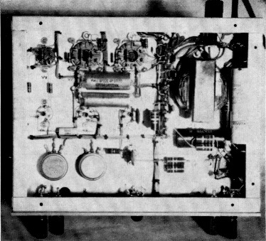
Bottom view of the wide-range power supply. In the lower left-hand corner, R7 is to the left, R5 to the right. One of the filament transformers appears in the upper right-hand corner.