RTTY: Diversity is worth the effort
The signal is there, clear and loud, and the teleprinter copy is fine. Several lines of message come out without interruption, and then the signal fades, grows quiet, and pinches out. Just for a second or two, then it's back. Hardly noticeable in a voice transmission, perhaps, but the printer has stopped, skipped a character and started off on a cycle of false operation, and several words are lost before the message picks up again. Then after another thirty seconds or so the signal again wavers, with the bell-like clink of multipath audible in the headphones. Again the machine runs wild briefly; this time the carriage skids back across the paper and the next line of copy is typed over the preceding one.
You know your equipment is working correctly ; it's just that the signal isn't there all the time. How wonderful it would be to be able to get rid of this fading trouble!
Diversity reception is based on this simple principle: The signal that fades out and is unreadable at your location is, likely as not, up to full strength at another location not 300 feet away. It isn't gone - it's just around the corner, or down the street, in the next lot, or maybe has shifted polarity. Since the actual percentage of time it is out at any one place is apt to be small, the random fade patterns at any two given locations, provided they are separated by certain distances, can combine to give a practically solid signal with nearly no fadeouts.
Multipath propagation is a very maddening form of trouble which can make strong signals completely useless very quickly. It can happen whenever the received signal consists of two or more components that have reached the receiver by different paths. Both paths are likely to be strong at certain times of the day for a given frequency, and if one is several hundred miles longer than the other the signal will arrive a few milliseconds later than the one coming by the shorter path. The resulting composite signal has areas where both f.s.k. tones appear to be on at once, with much "filling in" of the spaces when there is supposed to be no tone in one channel. This introduces an ambiguity in the positions of the crossovers from mark to space, and makes for very poor copy. It can be recognized by the peculiar bell-like ringing sound it makes. But like regular skip, the multipath effect fades in and out, and is greatly alleviated by diversity.
One thing that has deterred amateurs from trying diversity is the horrible-looking list of distances quoted by authorities as to how far apart the aerials must be. It has been stated that to achieve good results the two antennas should be about 9 wavelengths apart at the operating frequency. This is 600 feet at 14 Mc., 1200 feet at 7 Mc., and a whopping half mile at 3.5 Mc. Few people have property that rich. But suppose you could get, say, 90 per cent of the possible theoretical improvement with, say, 20 per cent of the theoretical distance? For our purposes, something very like that can be arranged.
The antennas that produced the copy shown here (and others like it) were just two half-wavelength pieces of wire a few feet off the ground. They were about 150 feet apart, and I could see both of them from my kitchen window. Of course, I had to drag something else in. One aerial is crosswise to the other. This can be carried too far, because if the signal is weak, one aerial may not pick it up at all. But directive antennas pointed in somewhat different directions offer additional help.
In practice, a combination of one good rotating multiband beam on a house tower used for both the transmitter and one receiver, coupled with a good dipole 150 feet away for the other receiver, is a perfectly acceptable setup. But we have achieved remarkable things with two aerials in essentially the same location, at opposite ends of a house, with one vertical and the other horizontal, so don't let a 50-foot lot throw you. It would seem that having the diversity and the two antennas is the thing that does the trick, not so much the absolute distance between them.
The radio energy received from two such locations must be combined in some way to get this effect. This is not as simple as it sounds. It doesn't suffice, for example, to have one huge aerial long enough to reach into both locations, perhaps shielded in the middle, and running to a receiver. The fading destroys the phase relationships between the two locations quite effectively, making them completely random, and two signals meeting on a common aerial interact to reinforce and cancel each other and make the fading as bad as before.
Practical Application
There are two chief methods of producing diversity for f.s.k., the d.c. switching method and the d.c. combining method. The combining method is used here because it is simpler, can be easily adapted to existing equipment, and is the only method that works well on multipath.
The first thing you need is two receivers, connected to your two aerials. The receivers don't have to be the same type or the same quality. All that is required is that both will tune to the frequency you want to listen to.
The next thing needed is two audio-type f.s.k. terminal units. If one complete one is already on hand, it will be necessary to build up another that duplicates its circuit, including the channel filters, up to the detectors or discriminator. A second keying circuit and loop output will not be needed, since the two receiver outputs will be combined in the TU detector circuit.
The detector/combiner circuit is shown in Fig. 1. Notice that there are two audio transformers for each receiver channel, one for each tone, and each driving a full-wave rectifier. The outputs are series added, effecting the diversity combining. The resulting combined voltage is used in my setup to drive the Schmitt trigger circuit shown in Fig. 2. This is a neon glow-tube device whose output suddenly trips from mark to space as the input voltage crosses zero. It is adjusted to work right on zero by R1, in the cathode circuit of VIA. This adjustment only has to be made once when it is set up. The Schmitt trigger is very accurate and sensitive. The second trigger is just a convenience to invert the positive-going square-wave signal for driving V3, which drives a polar relay. Relay output is used here to obtain a loop connection that is entirely floating from ground, an advantage in making connections to other equipment. It also takes a relatively-low loop-voltage source and has proven reliable in service.
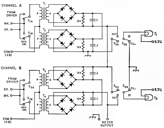
Fig. 1. Dual diversity detector/combiner. D.c. outputs are added in series. Resistances are in ohms (K = 1000); resistors are ½ watt. Capacitances are in pF; capacitors are paper. Diodes are 1N69 or equivalent.
| I1,I2 | 6.3 volt pilot lamp. |
| S1-S4, incl. | D.p.d.t. toggle. |
| T1-T4, incl. | Interstage audio, 10 k plate to grid (Stancor A4723). |
The Rectifier Circuit Theory
In normal operation, the two rectifier groups that are connected to the mark channels from each receiver produce, say, about + 3 volts each. These add to produce +6 volts with respect to ground which is applied to the Schmitt trigger, throwing it to mark. Then the f.s.k. tone shifts into the space channels, which are connected to two rectifier groups which produce -3 volts each. These add to produce -6 volts, which throws the Schmitt trigger to space.
Now suppose one set of tones from one receiver fades completely out. Then only the voltages from the other set are left, but the +3 and -3 volts continues to run the Schmitt trigger since it will respond accurately to as little as +0.2 volt. In a single-channel installation you would be losing copy during this fadeout.
Then the first tones fade back in and the other set fades out. Again the remaining set keeps the Schmitt trigger going. This is the operation during ordinary fades of signal strength.
Now suppose that bad multipath, or possibly some c.w. interference, hits the tones from one receiver. The effect of this is to "fill in" parts of the signal. When a tone should go off and the other tone come on, at a mark-to-space transition, the mark tone instead stays on for a while during the time the space tone is also on. Having both mark and space tones on at once gives both +3 and -3 volts output; these cancel each other, and the Schmitt trigger would chatter aimlessly. This is what happens in single-channel service. But added in series with this near-zero voltage is a correct +3 or -3 volts from the other receiver channel. This enables the Schmitt trigger to trip properly. Not until both channels are badly multipathed at once will trouble set in.
This is the reason for adding the voltages in series. It would be easy to combine them in parallel - in fact, this could be done to many types of terminal-unit circuits just as they stand - by installing jumpers at the detector circuit from one unit to the other. If you do that, your diversity will work for plain fading, but if one channel gets a voltage that doesn't belong there, say, a spurious 3 volts, the other tone has no way to overcome it. Even though both other tones are on, they can't rise above the 3-volt level to overcome the wrong 3-volt signal.
The 0.1 µF capacitors provide filtering for the rectifiers, giving a smooth, very square-looking output wave. Switches S2 and S4 are for shutting off each channel separately for tuning. When they are both off, a steady mark is maintained, as the Schmitt trigger is customarily set to fall into the mark condition when there is no signal at all applied to it. This is adjusted by R1, Fig. 2.
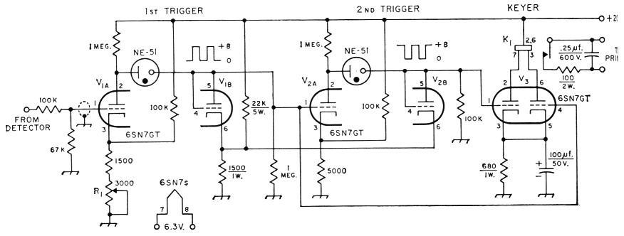
Fig. 2. Keyer circuit using Schmitt triggers. Resistances are in ohms (K = 1000); fixed resistors are'/ -watt, except as indicated. Capacitor with polarity marked is electrolytic.
| K1 | Polar relay (W.E. 215 or 255A). |
| R1 | Linear control, 2-watt wire-wound. |
Do not attempt to eliminate the audio transformers from the design. Circuits that substitute coupling capacitors for these transformers fail to produce accurate detection because the a.c. ground returns that are then necessary conflict with the series connection of the outputs that is also necessary. The result is that some rectifier outputs have much. more filtering on them than others, giving all different shapes of d.c. waves and destroying the symmetry.
This circuit will give best results in limiter-less TU's where there is nothing to bring up the noise level when signals fade. Square bandpass filters consisting of two or more toroids each are another improvement that pays off, and it should also be emphasized here that the use of voltage doubler or half-wave single-diode types of rectifiers is bad practice. The outputs of these rectifiers require such heavy filtering to produce smooth d.c. that the shape of the keying wave is severely rounded off, causing much ambiguity in the positions of mark and space crossovers, and hence much possibility of bias in the signal.
It has been said that the variable decision threshold detection system (DTC) eliminates the need for diversity. It is true that practically any installation will work better with DTC, and undoubtedly such a device can be neatly spliced into the circuit shown here between the rectifier groups and the Schmitt trigger. But no detection system, no matter how clever, can detect a signal that has faded completely out, and this is a condition that diversity is uniquely able to correct, especially with narrow shift where both tones tend to fade in the same pattern. Diversity and DTC are both valuable improvements.
Adjusting the detector circuit
Connect an oscilloscope to the grid of VIA. Feed an audio signal into one of the TU inputs, and center it in one of the filters. Adjust the level for a d.c. voltage of 3 or 4 volts or so at the grid of VIA. The signal should look reasonably clean of audio on the scope display. (If the scope won't read d.c. accurately because of a.c. coupling, a v.t.v.m. can be used to verify the measurements.) If nothing is seen at all, check to see that the steady-mark switch, 52 or S4, for the channel is open. The switch for the unused channel should be closed, causing the pilot warning light for that channel to be off, indicating the channel is blocked.
If this test is passed, move the audio to the other filter. The d.c. should reverse in polarity, but be otherwise about the same. Throwing the normal-reverse switch (Si or S3) which is used to "turn signals over" into the other position should also reverse the d.c. polarity. Repeat this check with the other receiver channel.
All this time the relay should be clicking back and forth with the reversals in polarity at the grid of VIA. Remove all signals coming into the TU and carefully turn R1 until the relay just will click back and forth with very little motion either way. Now check the loop current being keyed by the relay contacts and leave R1 in the position that just causes the relay to click into the loop current on, or mark hold, position.
This is the only adjustment for R1. Note that it will not correct bias coming in on signals ; the slope of the keying wave is much too steep for it to help significantly. Offsetting it will just produce errors.
Operation
Now it is time to put the diversity setup on the air. The only absolutely vital thing that must be checked on the receivers being used is the flatness of audio response. It is essential that the two audio tones of 2125 and 2975 c.p.s., or whatever tones your filters are tuned for, come out of the receiver at the same level.
Make a check of the output level at both audio frequencies while tuning a steady carrier or signal-generator output. If the amplitude of one tone is higher or lower than that of the other by more than a decibel or so, correct this with shaping capacitors in the receiver audio system.
Modern s.s.b. receivers often cannot reproduce an audio frequency as high as 2975 c.p.s. very well because of narrow i.f. filters. If one of these sets is being used, it may be expedient to design the audio filters in the TU for somewhat lower frequencies than the old standard ones.
Now, with the two receivers connected and a printer in the loop circuit, we are ready to tune up. Set the loop current to 60 mA first. Loop current must be surprisingly close to what it should be, to get full accuracy out of a pulling-magnet printer. Errors of more than a few milliamperes at 60 mA cannot be tolerated.
Tune one receiver to an f.s.k. signal, using whatever tuning indicator is provided in the TU. Now throw the appropriate mark-hold switch, and after the usual correction has been made with the normal-reverse switch, the machine should print. If it does, throw back the mark-hold switch and tune up the other receiver the same way. Try out its channel independently and get it working the machine. Make sure, of course, that the two receivers are tuned to the same signal.
When all is well, open up both mark-hold switches and you are on diversity reception.
Make the usual test with the printer receiving distributor adjusting arm for range and bias. Good copy over a range of about 20 to 80 is fine. This assumes that the machine is working right to begin with, of course, as checked with the key board. A more accurate check on the loop signal is to splice a 100-ohm resistor into the loop circuit and read the current wave-form across it with the scope.
Set the scope's sweep for about 5 c.p.s., and the whole-character pattern of the RTTY signal can and will sync on a tape-sent RTTY transmission. It will lock on the mark-to-space transition at the beginning of the start pulse. All you have to do is get the sync polarity right and the sweep set accurately enough. (This assumes a scope that will sweep at 5 c.p.s.) Synchronization is not necessary for tests, if the pattern will stand reasonably still. The visual test for bias is made by observing the shortest right-side-up square-wave pulse that you can see, and comparing it in your mind with the shortest upside-down pulse. If they are the same time duration, there is no bias. Bias as little as 5 percent can be spotted this way.
Remember that in a low-priced scope the sweep may be far from linear at the low speed of 5 c.p.s., so make your visual checks all in the same spot on the screen. Rounded-off wave shapes are not bias, and are usually produced by the inductance of the printer magnet.
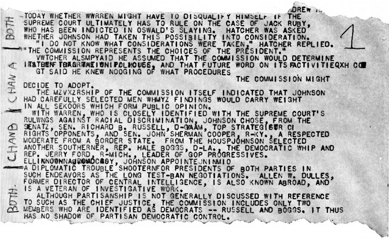
A tear-sheet of actual received copy showing the improvement effected by diversity. The top and bottom sections were made with both receivers, using the diversity system described. Copy from the individual receivers is in the middle two sections. Reproduced permission of United Press International.
If you see bias, go back and look at one of the audio outputs of the receiver to see if it seems to be in the signal itself. If not, check the Schmitt triggers with the scope, looking at the square-wave inputs and outputs to find the trouble. Almost always it will be in the relay-driver area, and then almost always in the relay itself.
Sometimes the neon trigger lamps work all right in a well-lighted room, but start jumping and skipping when the room is dark. This means the lamps are working marginally, using the light from the room to get enough ionization to fire. This condition sometimes develops after a few hours of normal operation. Install a new set; they're cheap. Once good ones are found they will last indefinitely. Mine have already outlasted some of the tubes.
C. H. COMBS.