A Center-Fed "Zepp" for 80 and 40
Fast QSY for the Phone-C.W. Operator
Multiband antennas fed with resonant feeders were very popular in the pre-coax cable days. This article is presented to review a good, but seemingly forgotten system. This antenna should be of interest to traffic and contest operators, and to the casual operator who likes to use both the c.w. and phone portions of the 80- and 40-meter bands.
Our section s.s.b. net meets on 3965 kc. and the c.w. net meets on 3575 kc. Many schemes were tried to make one antenna usable on both ends of the band so that a low s.w.r. could be maintained while securing efficient operation at the different frequencies. None of the antennas tried would permit an excursion of more than 300 kc. without a serious s.w.r. problem between the transmitter and the line. Getting from 80 to 40 meters with such an antenna was even more perplexing. The writer's dilemma was finally solved by the installation of the old reliable center-fed Zepp antenna.
Choosing the Dimensions
In order to use the antenna on 40, 75, and 80 meters, tuned feeders are required(1). So that the feeders can be matched to the transmitter, a transmatch is used at the "shack" end of the line. Parallel tuning is used to minimize the complexity of the transmatch. This requires that the transmission line presents a high impedance to the transmatch on both bands.
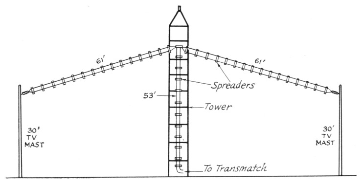
Fig. 1. Layout of the 2-bond Zepp antenna. Dimensions for each part of the antenna are shown. Feed point is anchored to one of the wooden support arms (See Fig. 3).
The charts in the handbooks did not give a set of Zepp antenna dimensions that were suitable for the author's installation. Because of the existing tower, which would permit the antenna to be supported at the 50-foot level, and because the ham shack was adjacent to the tower, the prescribed feeder lengths were not practical. A graph was plotted to show the frequency extremes to which the antenna would be tuned, showing the minimum and maximum impedance points across the bands. It was determined that the combined length of one leg of the feed line and one section of the dipole would be 114 feet.(2) A length of 53 feet was used for the feed line and each leg of the driven element was cut to 61 feet.
To broaden the antenna's response, the driven element's effective area was made larger by paralleling two lengths of No. 12 copper wire as shown in Figs. 1 and 2. With this arrangement, the Q of the antenna is lower, permitting the operator to QSY approximately 200 kc. without readjusting the transmatch.
Construction Notes
The driven element and the feed line are made from No. 12 copper wire. The 4-inch wide ceramic spreaders used to hold the feeder wires apart are made by the E. F. Johnson Co. Light-weight poly spacers are used to spread the driven-element wires and are sold as TV "clothespins" by the Telco Co. (Fig. 2). All of the spreaders are attached to the No. 12 wire by short pieces of No. 18 copper wire. The distance between the spreaders is 4 feet for both the driven element and the feed line.
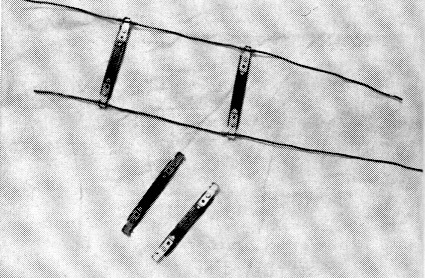
Fig. 2. Details showing how the driven element spreader are attached to the No. 12 wire. No. 18 copper wire is wrapped above and below each spreader to hold it in place.
Sections of 1 × 4-inch lumber are used to hold the feeders away from the steel tower (Fig. 3). Each piece is 24 inches long, notched at one end, and is fastened to the tower with U-bolts. Porcelain telephone-type insulators are attached to the feed-line end of each board, offering low-loss anchor points for the transmission line. The uppermost support arm, at the 50-foot level, is used as a mount for the center of the driven element.
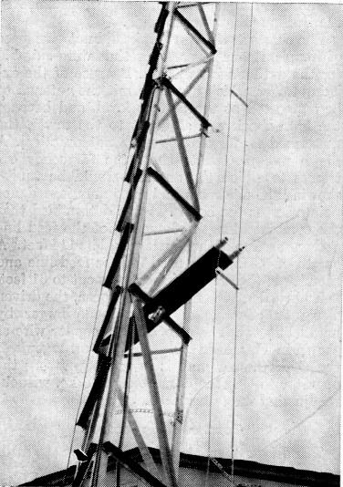
Fig. 3. Wooden support arms hold the transmission line away from the tower. Telephone-type insulators are mounted at the end of each board to make the feed line secure.
The far ends of the antenna are supported by 30-foot TV masts. A pulley and halyard arrangement is used for raising and lowering the ends of the antenna. Because the end supports are not as high as the feed point of the antenna, the dipole has a slight droop, but this does not seem to impair the performance.
The transmission line is brought into the operating position by means of feed-through insulators, mounted on a plywood strip which fits under a partially raised window. Insulated No. 12 house wire is used between the feed-through insulators and the transmatch.
Transmatch
Ideas for the author's tuner (Fig. 4) were taken from the excellent transmatch article by McCoy.(3) Band changing is made possible by a large ceramic switch (origin unknown) which was obtained at a hamfest. An identical switch is used for selecting the taps for the feed line (Fig. 5). Coil L1 contains 56 turns of No. 14 wire, is 3 inches in diameter, and has 8 turnsper-inch (Air Dux 2408T). A stationary link, L2, at the center of L1, contains 8 turns of No. 14 wire and is a part of the Air Dux coil from which L1 is made. The link is tuned with a 300-pf. variable capacitor. The author did not have a unit of the correct type, so two 150-pF capacitors were parallel-connected (mounted under the chassis). Capacitor C1 is a 100 pF per section variable with wide spacing. To give L1 some rigidity, it is mounted on a plexiglass tube which is supported by the frame of C1 with stand-off insulators.
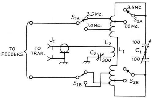
Fig. 4. Schematic diagram of the W4NML transmatch.
| C1 | 100 pF per section transmitting variable. (Split stator type with 0.175-inch spacing between plates.) |
| C2 | 300 pF variable capacitor(0.078 spacing or greater). |
| J1 | SO239 coax connector. |
| L1 | 56 turns, 3-inch diam., 8 turns per inch coil. S1 taps are 9 turns from ends of coil for 80 meters, and are 22 turns from ends of coil for 40 meters. S2 taps are 5 turns from ends of coil for 80 meters and 17 turns from ends of coil for 40 meters. (Air Dux 2408T or Polycoils 1779 usable.) |
| L2 | 8 turns of Air Dux 2408T (center portion of Li). |
| S1,S2 | Ceramic rotary, 2 poles, 2 positions, 2 sections. |
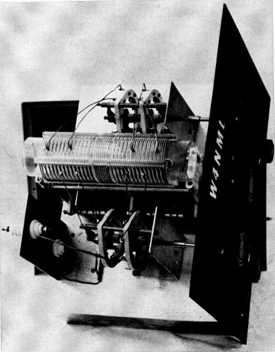
Fig. 5. Top-chassis view of the transmatch. C2 is mounted under the chassis.
Results
While using clip leads, the correct tap points for the feeders were found by operating the transmitter through a Collins wattmeter and tuning C1 and C2 for zero reflected power. The transmatch permitted the transmitter to "see" 50 ohms in any part of either band. After establishing the correct tap points for the feed line, permanent connections were made between L1 and the switches.Next, the tuner was used with the 30L-1 amplifier at an output level of 700 watts. After a 30-minute QSO, no evidence of coil heating could be detected.
Results
When compared to other antenna systems used by the author, the new skywire showed improved performance. It was believed that some sacrifice in efficiency would result from changing to the new antenna. Happily, it was found that we could have our cake, and eat it too! Extended use indicated that the performance was, indeed, better than with previous antennas used.
I wish to thank three friends for their help in making this article possible: K4WWN for his tower climbing and photography work, K4ADK for building the transmatch cabinet, and Roy LeCrone for additional darkroom and photographic assistance.
Although this antenna system is an old standard, it may be the answer to your QSY problems. The cost is nominal and the results are most rewarding.
Notes
- Center-fed Antennas, A.R.R.L. Antenna Book, Chapter 6.
- This length is generally 145 feet for operation in the 3.5 to 30 Mc. range when the antenna is mounted horizontally (no droop), away from steel towers, and with a single-wire driven element. - Editor
- QST, July 1965.
William C. Gann, W4NML.