The "Stanley steamer"
A 2-KW. P.E.P. linear amplifier with vapor-phase cooling
Get acquainted with a new (in the amateur world, at least) method of cooling high-power tubes. Called vapor-phase cooling, it lets tubes operate at a lower temperature than the more-familiar cooling methods, requires no fans or pumps, and is completely silent in operation. The tube used in the amplifier described here is now commercially available, costs about the same as its air-cooled counterpart.
Forced air cooling is "old hat" to modern radio amateurs who run the maximum power level; during the past decade tubes and components have diminished in size and convection-cooled tubes have given way to forced-aircooled tubes in amateur gear. In some instances, water-cooled tubes have been featured in specialized equipment. In all cases, however, the nuisance of providing mechanical means of moving the coolant past the tube has been a major headache. Most blowers designed to move appreciable quantities of air have proven to be noisy at best, and a blower with a bad bearing or erratic rotor blades can be intolerable. Thus, by default, high-power operation has come to indicate noisy movement of air past the amplifier tubes.
A recent commercial development in the field of vacuum-tube cooling has been the Eimac vapor-phase cooling system. This article describes this system and illustrates its application in the design of a high-power linear amplifier for amateur service. The few people who have heard of this new cooling technique for transmitting tubes have ignored the principle of vapor-phase cooling by saying, "Oh, that's the system invented by some Frenchman - how can you cool powergrid-tube anodes with boiling water?" Not only can it be done, but in many cases it is far superior to either air or water cooling because it utilizes the highly efficient "latent heat of vaporization" principle.
In 1949 a French engineer, Charles Beurtheret of Compagnie Francaise Thomson Huston (CFTH) in Paris, France, applied the vaporization cooling principle to large external-anode transmitting tubes. He constructed a tube using a thick copper anode with pineapple-like fins, then immersed it in a water-filled boiler. As a result he was able to double the plate dissipation capability over that of a water-cooled tube, and more than triple that of an air-cooled transmitting tube. He also verified his prediction that by using this principle he could build a cooling system that had no pumps, blowers, fans, or, in fact, any moving parts or rotating machinery. Beurtheret's idea resulted in a less expensive, more efficient, and completely-silent cooling system. In 1951 a high-power broadcast station was built and sold to the French Government, the first station to be cooled by steam.
If you have a kilowatt linear, you know how annoying it can be to try to copy a weak c.w. signal over the noise of the air blower in the final amplifier. Most operators tolerate this nuisance as one of the penalties which result from running the legal power limit. When a vapor-cooled amplifier is put into service the major source of noise is eliminated. No motor is required to actuate the cooling system. However, this writer suddenly discovered the noise from the 75-cent fan motor in his exciter now sounded like a double-decker Greyhound bus in the Holland Tunnel! A pair of wire cutters quickly solved this last remaining objection. Then silence reigned supreme.
How vapor-phase cooling works
Conventional cooling systems have used forced air or circulating water as a heat-transfer medium. However, these methods have their limitations. Vapor-cooling of power tubes owes much of its appeal to its high heat-transfer efficiency, as shown in the following summary.
Comparison of cooling methods
Air - In a forced-air cooling system, air is forced past the external anode fins of the tube to absorb and dissipate the heat. Air is a relatively poor heat conductor, however, and in terms of power densities, forced-air systems are capable of removing only about 50 watts of power per square centimeter of effective internal anode area.
Water -Higher power densities are practical in water-cooled systems. Typically, circulating water removes approximately 100 watts per square centimeter. Thus, a power tube using circulating water as a heat-transfer medium is capable of approximately twice the plate dissipation rating of its air-cooled counterpart. Water temperature must be limited, however, so that steam is not generated inside the tube water jacket, causing localized hot spots which may destroy the tube. In practice, the temperature of water leaving the tube is limited to 70° C. to preclude the possibility of spot boiling. This heated water is then passed. through a waterto-air or water-to-water heat exchanger where it is cooled to approximately 40° C. before being pumped over the tube anode again.
Vapor - Vapor-phase cooling systems eliminate some of the disadvantages of both systems by exploiting the latent heat of vaporization of water. Raising the temperature of one gram of water from 40° C. to 70° C. (as in a water system) requires 30 calories of energy. Transforming one gram of water at 100° C. to steam vapor requires 540 calories. In a vapor-cooling system, a given quantity of water will remove nearly twenty times as much energy as in a water-cooling system. Power densities as high as 500 watts per square centimeter of effective internal anode surface at atmospheric pressure have been attained through vapor-phase cooling. A typical vapor-phase cooling installation consists of a tube with a specially designed anode immersed in a "boiler" filled with distilled water (Fig. 1). When power is applied to the tube, anode dissipation heats the water to 100° C.; further applied energy causes the water to boil and to be converted into steam vapor. The hot vapor is passed through a condenser(1) where it gives up its energy and is converted back to the liquid state. This condensate is then returned to the boiler, completing the cycle.
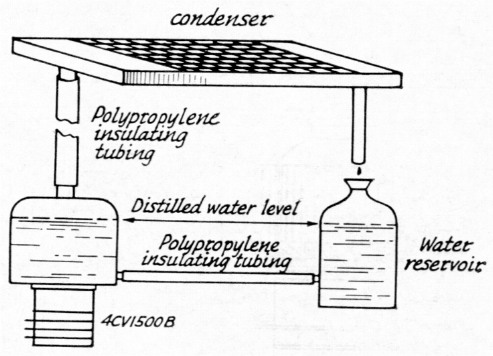
Fig. 1. The vapor-cooling "circuit." Steam generated by boiling water in the tank around the tube anode rises to the condenser, where it is cooled and converted back to water which drips into the reservoir.
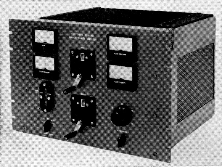
Apart from the relay-rack panel and chassis, the vaporphase-cooled 4CV1500B amplifier departs from the conventional in appearance. On top of the enclosure is a heat radiator constructed along the same lines as a car radiator. The water-level indicator and counter dials lend a different touch to the panel layout. Capable of an easy kilowatt average-d.c. input, the amplifier is silent in operation and the tube actually runs cooler than its air-cooled equivalent would with forced-air cooling.
A Vapor-Cooled Tube
The new highly-linear 4CX1500B was chosen as an experimental vapor-cooled tube. Heavy vertical copper fins were first brazed to the bare anode of the tube, then an integral boiler with the same outside diameter as the regular air-cooled fin radiator was affixed to the tube. A distilled-water inlet of ¼ inch copper tubing was installed at the base of the boiler and a 1 inch diameter steam outlet was placed in the top (Fig. 2).
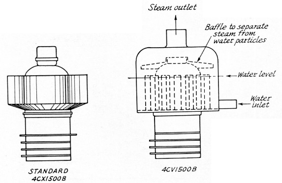
Fig. 2. The "boiler" for the 4CV1500B.
The 4CX1500B is a recent version of the well known 4CX1000A with improved intermodulation distortion characteristics of at least -40 dB 3rd-order at 1 kW. It has the same external dimensions and appearance; however, the internal geometry has been optimized using new computer design techniques. This new vapor-cooled version has been designated the 4CV1500B. Had a larger boiler been employed, the anode dissipation could have been rated at 3 kW. However, in amateur service this rating could not have been utilized. It was desirable to keep the boiler diameter to a minimum, hence the more than ample 1500 watt dissipation rating. Any standard external-anode tube type could be made with the vapor-phase-cooled anode. The 4CV1500B was chosen only as a vehicle to demonstrate the principle.
The "Stanley Steamer" Circuit
The circuit and layout of the "Compact AB1 Kilowatt"(2) amplifier by Ray Rinaudo, W6KEV, was used as the design for the vapor-phase cooling amplifier. It is difficult to improve upon the parts, layout, and circuitry which Ray designed.
Under typical operating conditions this AB1 linear amplifier has an average input of 1000 watts, which results in approximately 400 watts of plate dissipation, assuming 60% plate efficiency. This heat causes the water surrounding the anode to change to steam. Under a slight positive pressure, the steam flows up through the polypropylene plastic insulating tube to the condenser mounted in the lid of the amplifier.
The energy from the steam is dissipated by the convection-cooled radiator and the steam is changed back into the water, or liquid, state. The water then flows by gravity into the plastic reservoir. This reservoir and the 4CV1500B integral boiler are connected together by means of a ¼ inch plastic tube to provide the return input water path and to complete the cycle. The water level in the tube boiler is, of course, dependent upon the level in the reservoir. The level gauge on the front panel is connected to the reservoir and provides a visual check of the system.
Pyrex or polypropylene plastic tubing is utilized for the water inlet and steam outlets, providing d.c. and r.f. isolation between the tube anode and ground. A one-quart plastic container is used to store the distilled cooling water. The water level can vary by as much as 3 inch over the length of the anode surface and still supply ample cooling. In actual practice it has been found necessary to add only a few ounces of water every four to five weeks of normal operating time.
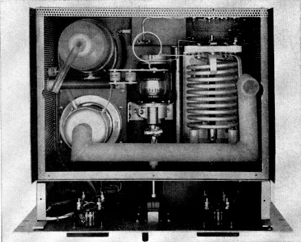
The plastic water pipe helps give the interior of the amplifier the look of a piece of power-house equipment. The water reservoir is in the upper left corner in this view. The radiator, which connects to the plastic tube at the left and the pipe opening at the right, covers this equipment in regular operation.
A steam condenser, Model ME-56073, measuring 11½ × 16½ × 2 inches, was obtained from the Liberty Radiator Core Company, 250 14th Street, San Francisco, California. It is constructed in the same manner as that of an automobile radiator using several straight-through parallel paths, and is made of copper parts silver-soldered together. Brass or soft-soldered parts should not be used in vapor-cooling systems as the steam will attack such materials. These impurities will contaminate the cooling water and cause high d.c. leakage current. This leakage promotes electrolytic action which in turn attacks the brass or solder joints and results in water leakage. If copper is chosen for all materials which come in contact with the water or steam, none of foregoing difficulties will be encountered. These basic rules have been used over the years in water-cooled systems.
The condenser also forms the r.f. shield and top lid of the amplifier and is cooled by natural air convection. It is capable of fully condensing steam up to anode dissipation levels of at least 600 watts. The condenser is mounted with the steam inlet end slightly elevated over the water outlet end so that the water drains easily back into the reservoir. As mentioned previously, no pumps, fans or blower are required. It is a straightforward, simple, efficient and absolutely silent cooling system.
Many air-cooled ceramic-metal tetrodes are rated at a maximum anode core or seal temperature of 250° C. For longer tube life, most equipment is designed to operate below this maximum, with typical temperatures ranging between 150 and 200° C. A properly designed vaporphase-cooled anode at rated dissipation operates at between 100 and 115° C. maximum. Strange as it may sound, a steam-cooled anode actually runs cooler than most air-cooled tubes.
| Plate Voltage | 2900 V | 2500 V | 2000 V |
| Plate Current (static) | 300 mA | 300 mA | 300 mA |
| Screen Voltage | 225 V | 200 V | 225 V |
| Control Grid Bias | -34.0 V | -31.5 V | -37.0 V |
| Plate Load Resistance | 2200 Ω | 2200 Ω | 1600 Ω |
| R.F. Output Impedance | 52 Ω | ||
| Filament | 6.0 V. a.c. at 10 A | ||
R.F. drive should be adjusted in all cases to a plate-current level of 1 kW input on c.w. or 2 kW p.e.p. on single sideband.
Amplifier Construction
The front is a standard durai aluminum relay-rack panel measuring 12¼ × 19 × 1/8 inches. The cabinet is 16½ inches wide, 12 inches high and 15 inches deep. A 3-inch section directly behind the front panel furnishes a shielded enclosure for the meters, filament transformer, bias control, meter switch, and water-level indicator as well as the pi-network input and output dial mechanisms. To eliminate TVI, shielded conductors pass from the terminal box at the rear of the cabinet through 1000-pf. feed-through capacitors, then through %-inch conduit to the section behind the front panel and to the 4CV1500B tube subchassis.
The front panel contains four 3-inch square meters (Weston Model 1921, black bakelite case). Three are used for monitoring plate and screen currents and plate voltage. The fourth is a 0-1 milliammeter which can be switched to read control-grid current, bias voltage, screen voltage, or to sample the rectified 50-ohm r.f. output voltage. There are two counter dials, for tuning the input and output capacitors of the pi-network. A band switch, bias control, meter switch, and water level gage complete the front-panel layout.
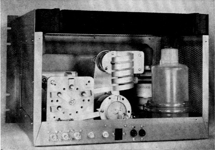
The rear view shows the radiator in place at the top, with the reservoir at the right and the amplifier tube partly concealed by it. The plate tank coil and vacuum variables are easily recognized.
The schematic and parts list in Fig. 3 shows that the r.f. input circuit is untuned and utilizes a 100-ohm 50-watt noninductive wire-wound resistor. Amplifier neutralization is not required when terminating the r.f. drive into this resistor, and amplifier stability is excellent. Only 15-20 watts peak drive is required to produce the full 1-kw. average or 2-kw. p.e.p. input power. A standard r.f. attenuator pad should be used between a 150-200 watt exciter and the amplifier input circuit.
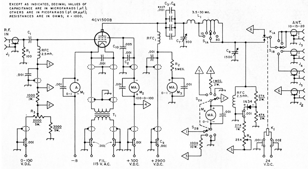
Fig. 3. Circuit diagram of the 4CV1500B amplifier. All 0.001 µF feed-through type capacitors not listed below are 500-voltrating (Erie CK70AW102M or equivalent); other 0.001-µf. capacitors are disk ceramic, 500 volts.
| C1-C6, inc. | 0.001 µf., 4000 volts (Centralab 858S). |
| C7 | 300 pR vacuum variable, 5000 volts (Jennings UCSL). |
| C8 | 1500 pF vacuum variable, 3000 volts (Jennings UCSL). |
| C9 | 0.001 µF, 4000-volt feed-through (Erie type 2498). |
| C10 | 0.0015 µF, 400 volts (part of Eimac SK800B air-system socket). |
| J1,J2 | Chassis-mounting coaxial connectors, BNC. |
| J2,J3,J4 | Chassis-mounting coaxial connectors, UG-58A/U or SO-239). |
| K1 | Vacuum relay, s.p.d.t., 24-volt d.c. coil (Jennings RP A). |
| L1 | Turret tank inductor (B & W 852). |
| M1 | 0-1 d.c. ammeter (Weston 1921). |
| M2 | Zero-center d.c. milliammeter, 100-0-100 (Weston 1921). |
| M3,M4 | 0-1 d.c. milliammeter (Weston 1921). |
| R1 | 100 ohms; two 50-ohm, 25-watt noninductive resistors in series. |
| R2 | 5 megohms, 10 watts; five 1 megohm, 2-watt resistors in series. |
| R3 | 2000 ohm, 5-watt linear control. |
| R4 | 25,000 ohm linear control. |
| RFC1 | 500-mA plate choke (B&W 8001. |
| S1 | Part of L1 (see text). |
| S2 | Rotary, 2 poles, 1 section, 5 positions (4 positions used). |
| T1 | Filament transformer, 6 volts, 10 amp. |
The plate tank is a B&W Model 852 inductor with a "piggy-back" rotary switch coupled to the shaft to automatically select the proper antenna. (This switch was added after the photographs were taken.) Coax connectors are provided on the rear of the cabinet to accommodate 10, 15, 20, 40, and 80 meter antennas. A Jennings Model RJ1A vacuum switch serves as the antenna change-over relay to feed the proper antenna back to the receiver. No forced-air filament-seal cooling is required for the tube as it too, is cooled by natural convection and operates at less than 200° C. if proper ventilation is provided.
The tube socket is mounted on a subchassis plenum box. The amplifier is rack mounted, and the area directly under the tube subchassis is open, serving as the air intake. A piece of perforated aluminum covers this opening. Care should be taken in furnishing sufficient air to maintain seal temperatures at or below 200° C. "Templar" colored wax painted on these areas will indicate the temperatures.
This 4CV1500B linear amplifier is the ultimate in amateur equipment. The low-intermodulation-distortion tetrode produces a sharp, clean transmitted signal. The elimination of the air blower noises enables the amateur to receive weak DX signals in the complete silence of the ham shack.
A special debt of gratitude goes to Bob Sutherland, W6UOV, for the use of his shop tools in making the various brackets and cabinetry and for his assistance and words of encouragement.
With the expanding use of the alternator-rectifier system for keeping the car battery charged, the design and construction of mobile power supplies for communications gear begins to parallel ordinary line powered practice.
Notes
- A capacitor stores electrical energy. A condenser converts steam to water.
- Article published in the November 1957 QST.
Jack Quinn, W6MJG.