A transistorless 300-Watt mobile power supply
The mobile power supply described in this article operates from a standard automobile alternator and produces d.c. operating voltages directly from the three-phase, 14-volt input.(1) This method eliminates the need for expensive power-consuming, low-voltage rectification and chopper transistor stages. Furthermore, voltages produced by this supply are essentially independent of engine speed and load. The efficiency realized is higher than for other types of mobile supplies. The supply can be built using new parts for about half the cost of a conventional transistorized power supply of equivalent rating. Even further savings can be realized by raiding the junk box and browsing through the local surplus store.
Obtaining The Three-Phase Input
The 1965 Chevrolet in which this supply is used is equipped with a stock 55 amp. Delcotron alternator. The six rectifier diodes which provide the d.c. output for normal automobile requirements are mounted on the rear shell of the alternator case. The three-phase a.c. output from the alternator windings must be obtained by removing the rear half of the case and making connections to the three machine-screw terminals. These wires can easily be routed through existing openings in the case. The output cable should be securely clamped to the alternator case.
Reassembly of the alternator is not difficult, but requires some care. The brushes and springs must be placed within the inside of the case and held in position during reassembly. A small slot is located in the rear shell just above the rear shaft bearing, and a special tool is normally inserted at this point to hold the brushes in place temporarily. Lacking this tool, a short length of wire was used. The brushes were inserted and the wire was routed through the slot and completely around the case. The ends of the wire were twisted together to maintain tension and hold the brushes in place. The rear shell of the alternator was then mated to the front half, but was not quite seated. At this point the wire was carefully removed, allowing the brushes to drop into place. Finally, the shell was seated and bolted, completing the installation.
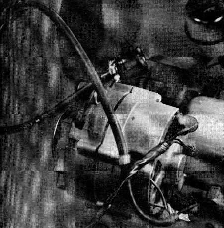
Fig. 1. The "modification" of the alternator consists only of bringing three leads out from the three-phase a.c. terminals. In the installation described, these leads go to a cable-mounting plug which connects the 3-phase a.c. to the power unit shown in Fig. 3.
Operation
Ideally, the transformers shown in the circuit of Fig. 2 would have 12 volt primaries and multiple taps on their high voltage secondaries. Practically, however, there are no such transformers generally available. The transformers used in this design should be satisfactory for most applications. They are standard control transformers with 115/230 volt primaries and 12 volt secondaries. They are installed using the 12-volt secondary as a primary. The 115/230-volt windings are connected to bridge rectifiers and the outputs of these are connected in series.
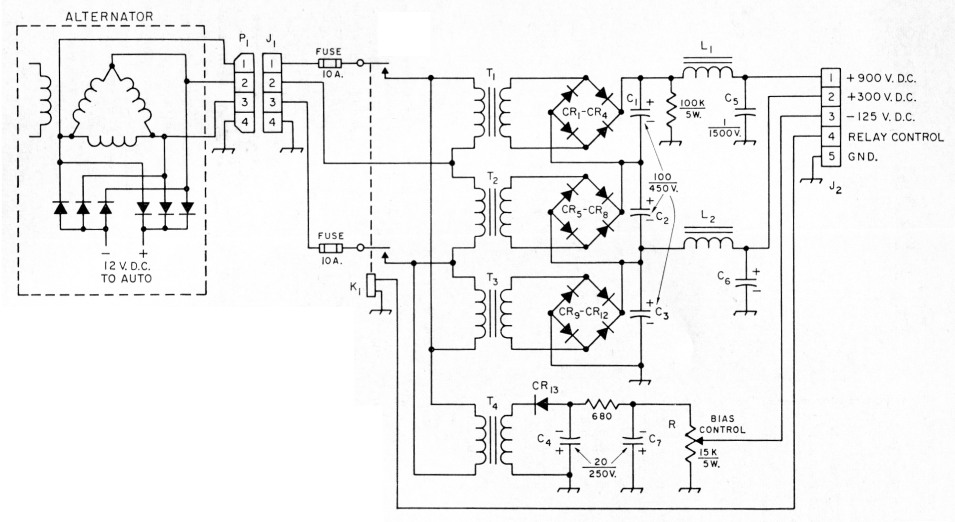
Fig. 2. The power-supply circuit. All capacitors are electrolytic and capacitances are in µF. Resistances are in ohms; K = 1000. Except as indicated, fixed resistors are ½ watt.
| C1-C6 | 100 µF, 450 volts. |
| CR1-C12, incl. | Silicon diodes, 600 p.i.v., 750 mA. |
| CR13 | Silicon diode, 400 p.i.v., 200 mA. |
| J1 | 4 contact male chassis-mounting connector (Amphenol 86-CP4). |
| J2 | 8 contact socket (Amphenol 7858). |
| K1 | D.p.s.t. relay, 12 volts d.c. with 10 amp. contacts (Potter and Brumfield PR5DY usable). |
| L1,L2 | 2.8 henry 300 mA smoothing choke (Stancor C-2334 usable). |
| P1 | 4 contact female cable-mounting connector (Amphenol 78-PF4). |
| R | Wire-wound control (Mallory VW-15K or equivalent). |
| T1,T2,T3 | Control transformer; 115/230-volt primary, 12-volt 8-amp, secondary, windings reversed; see text (Stancor P-6378 usable). |
| T4 | Control transformer; 115/230-volt primary, 12-volt, 4 amp. secondary, windings reversed (Stancor P-6376 usable). |
A variety of voltages can be obtained without resort to power-consuming voltage dividers by selecting either the 115 volt or the 230 volt secondaries of the transformers. The maximum voltage obtainable should be about 900 volts, and this can be reduced in increments of 150 volts by substituting the 115 volt for the 230 volt windings. An overall reduction in voltage of about 42 per cent can be obtained by connecting the transformer primaries in "Y" configuration, rather than in "delta." Using the Stancor P-6378 8-amp. transformer, the power supply is very conservatively rated at 300 watts under continuous service. This does not include filament power, which is taken directly from the 12-volt automobile supply. A somewhat less expensive supply can be built around the Stancor P-6377 4 amp. transformer which will deliver, again conservatively, 150 watts in continuous service.
Lower B-plus voltages are obtained by tapping down on the bridge rectifier outputs. A very stable 300 volt supply is obtained at the top of the CR9-CR12 bridge rectifier, as shown in the schematic diagram, Fig. 2. A separate bias supply is connected across one phase of the input. The slight imbalance between the loads on each leg of the three-phase supply does not affect voltage regulation noticeably.
Filtering is accomplished by a capacitor-input, pi-section filter for each supply voltage. Because the a.c. input is relatively high frequency (about 180 c.p.s. at engine idling speed), consists of three phases, and has a somewhat flat-topped wave-shape, the ripple at the rectifier output is quite low. With the filters the ripple is less than one per cent.
The voltage regulation of this supply is excellent. With a load of 150 watts, the output varies less than one per cent from idling to high engine r.p.m. At the full load of 300 watts the variation is less than five per cent over the full range of engine speed.
Construction
The parts arrangement is shown in Fig. 3. A 9 × 10 × 2-inch chassis was used to permit installation in a niche behind the automobile headlight. A slightly larger chassis would have been more convenient, but the arrangement of parts is not at all critical and an unlimited number of chassis shapes could be devised to fit various places in the automobile. Normal construction practices for mobile equipment should be followed. The cans of capacitors C1, C2, C4, and C7 are at dangerous potentials and should be insulated.
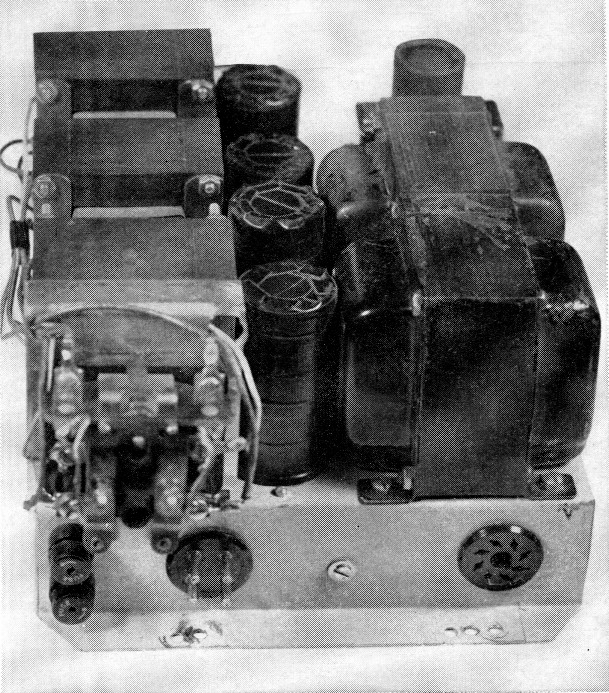
Fig. 3. Regular chassis mounting is used for the four transformers, rectifiers, filter capacitors, and diodes. The relay and remaining components shown in Fig. 2 are also on this chassis. Note that the capacitors are covered with electrical tape for preventing accidental cortact with the metal cans.
Operation
A 12-volt s.p.d.t. relay is provided to turn the supply on and off. Because this power supply requires no warmup time before delivering its rated output, it is suggested that provision be made to prevent the application of high voltage prior to applying filament voltage to the equipment. A simple system for doing this is shown in Fig. 4.
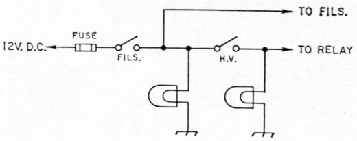
Fig. 4. Simple control system for permitting tube heaters in receiver and transmitter to be turned on before high voltage is applied.
Of course it is obvious that the engine must be running for the power supply to operate. There are some who might consider this to be a disadvantage. If you have ever found yourself stranded on a lonely road with a dead battery, you might care to disagree!
Notes
- A similar system has been described by Jennings ("Three-Phase Power Supply for Mobile Use," January 1956 QST), using a specially-built transformer designed for high-frequency a.c. - Editor.
Frank A. Exum, W0GIL,
Irvin D. Johnson, KOHLZ.