High-performance RTTY filters 1
Improved designs for better reception
Most RTTY converters in amateur service use quite simple filters for separating the two tones of frequency-shift keying. The new concepts using limiter-less two-tone reception give much better copy when teamed with well-designed filters. In this article the author describes several filter systems designed specifically for use with the Mainline TT/L f.s.k. demodulator. The filters can be built at very modest cost.
In a day when rapid progress is being made in all technological fields, radioteletype has its share of advances. Limiterless a.m. (sometimes called "two-tone") reception has been developed to a level where it offers reliable copy under conditions where conventional demodulators using a limiter fail badly. Even f.m. reception using limiters has been substantially improved. Automatic-threshold computers now enable single demodulators to give diversity reception with fewer errors and better copy than old-style dual-diversity units using separate antennas and receivers. The Mainline TT/L f.s.k. demodulator(1) is an outstanding example of the application of these new concepts.
The selection and proper use of filters for the RTTY demodulator offers the greatest potential improvement that can be made, since in all but a few isolated cases quite elementary filters are being used. The filters in the Mainline TT/L were of this simple variety, using easily-obtained TV width coils. Such a filter system offers excellent reception under many conditions, especially when signals are strong and when unstable transmitters or improper shift are being used. In this case the limiter may be left on, and full use of the unattended autostart facilities is available.
However, when conditions are less than optimum - static, impulse noises, deep selective fading and, in particular, adjacent-channel interference such as c.w. - simple filters, with or without the limiter, can do very little. At a time like this most operators just throw up their hands and quit for the day. It takes more complex filters to separate the desired signal from the surrounding noise. Such filters are rather expensive when purchased commercially.
This paper will show how filters comparable in quality to commercial units costing $40 and more each can be made at a cost of less than $3. Yet they can be easily constructed, with surprising precision. Since these filter systems are so inexpensive, the operator can easily construct several of them and then quickly choose the one that suits the conditions the best. As with a good receiver, varying the filter selectivity will often mean the difference between good copy and no copy.
How Narrow Can We Go?
Since the RTTY signal is a pulse-modulated f.s.k. carrier, it does exhibit a certain bandwidth.
The modulating signal consists of a fundamental frequency determined by the pulse rate, with harmonics determined by the pulse shape. The fundamental audio frequency for 22-ms. pulses will be approximately 22.5 cycles. While the filters for mark and space could be as narrow as 45 cycles and still retain the essential keyed information of a 60-w.p.m. RTTY signal, you wouldn't want a filter that narrow. Such narrow filters can readily introduce distortion if the signal is not properly centered in the passband. However, the biggest objection is that the transmitted signal may not be exactly the right shift to fit the specific filters. An associated problem, nearly as serious, is the stability of the transmitter and receiver; obviously the closer the filter gets to minimum bandwidth the more critical the tuning becomes. So you don't get something without being inconvenienced elsewhere. For this reason the broadest filter system that conditions warrant is normally used.
The author suggests that filters of 65-90 cycles bandwidth perhaps fall in the "minimum bandwidth" category. A most interesting technical paper was published by Vic Poor, K3NI0(2) on this subject, and many of his ideas have been used by the author in the development of the filters to be described. Anyone interested in following up this subject should make an effort to read K3NIO's excellent article.
What filter?
In general, the broadest filter that is compatible with band conditions would be a safe bet. If there was never any interference from a nearby station, the more simple filters would do an excellent job most of the time. Their broad bandwidths would give good reception on shifts which only vaguely resembled "normal," and would tolerate large amounts of drift in the incoming signal. However, this utopia just does not exist, not even on "clear" commercial channels.
Unfortunately, on frequencies which must be shared with all comers - a situation peculiar to amateur radio - conditions change, and at an entirely unpredictable rate. What may have been a clear frequency for the past hour or so could in the next moment be clobbered by a strong interfering signal. In this situation the e: thusiast who has some-means of quickly changing to a different technique has a tremendous advantage over his less versatile counterpart.
Another factor is that many stations are finding that changing to 170-cycle shift, rather than 850, will greatly reduce loss of copy, especially in the case of interference from c.w. stations. Thus the addition of a filter system that i3 intended primarily for 170 shift should be considered particularly by the operator interested in traffic handling, where errors require repbats and wasted time. Several unattended autostart nets on 80 meters also are getting reliable unattended operation on 170 shift where 850 shift previously gave poor results. Although frequency stability is a greater problem than on 850 shift, the results have more than justified the extra care required.
We should like to suggest, then, that three filter systems be considered by those wishing to obtain maximum benefit from the TT/L demodulator:
- A broad-filter system for general receptionautostart of strong signals where "walk-away is beneficial.
- A narrow-bandwidth system exhibiting good skirt selectivity for 850-shift copy in limiter-less mode, where interference, weak signals, and selective fading are factors. These same filters, copy during stattic, aurora (fast) will and similar conditions.
- Narrow filters for 170 shift.
The 88 mH toroid
The original Mainline TT/L used TV width coils for several good reasons: first, they can be obtained at any radio-supply house; second, they are adjustable and thus can be tuned to the proper frequency; third, they are easy to install; and fourth, they present a nearly ideal bandwidth for general reception from extremely narrow to more-than-legal shifts.
However, the 88 mH toroids have been quite popular with amateurs who build RTTY equipment, as they are relatively easy to obtain (check the listings in the Ham-Ads in any QST issue) and are quite inexpensive when compared with any other suitable inductor - as little as 35 cents each when purchased in groups of five or more.
The 88-mH toroid has a quite high Q which makes it ideal for use in some types of filters, but in a simple single-tuned filter the Q could be too high to be satisfactory. For instance, the Q of a TV coil when adjusted to resonate at 2125 cycles with a 0.15 µF capacitor would be about 7, while the 88 mH toroid at this frequency (resonated with 0.064 µF) would have a Q of nearly 120, if isolated properly. The bandwidth with the TV coil would be about 300 cycles, but with the 88 mH toroid would be only about 19 cycles - much too sharp to make a good RTTY filter. (However, it is this property of the toroid that makes it a good tuning indicator under certain conditions, and the Mainline TT/0 Semi-Counter takes advantage of the high Q to determine frequencies quite accurately for tuning filters or for checking shifts. Fig. 1 shows Q vs. frequency for a representative 88 mH toroid. Additional information on the toroid can be found in May QST.(3)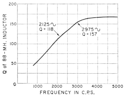
Fig. 1. Q vs. frequency for an 88 mH toroid, western Electric type 632.
Ralph Leland, W8DLT, was kind enough to supply the data below, obtained from the manufacturer's (Western Electric) manual:
| New Coil | Superceded Coil | Inductance | D.C. Resistance | 1000-Cycle Resistance |
|---|---|---|---|---|
| 632 | 622 | 88 mH | 9.0 Ω | 9.8 Ω |
| 638 | 44 mH | 5.1 Ω | 5.5 Ω | |
| 628 | 44 mH | 4.7 Ω | 5.1 Ω | |
| 639 | 22 mH | 2.6 Ω | 2.8 Ω | |
| 629 | 22 mH | 2.5 Ω | 2.7 Ω |
The resistance values include 7½ feet of 22-gauge cable. The 1000-cycle resistance is for a current of 0.5 mA. These are the coil numbers, not the case numbers that most telephone company personnel would use.
Ralph continues that the toroid nearly everyone obtains these days is the type 632, which is about 50 per cent smaller than the older 622. The reduction results from the use of Formes wire; there was no change in the core material used.
Using the 88 mH toroid in filters
When used properly, the 88 mH toroid makes an excellent basic filter element. To lower the Q to where the bandwidth of the simple single-tuned toroid would make a good filter, resistance can be put either in series or parallel with the inductor.
The parallel impedance of such a circuit goes up with frequency, so the voltage developed across the filter will be much higher for the higher frequencies: Thus, combining mark and space filters on the same drive point in such a manner that the output voltage will be the same for both frequencies, while retaining the same bandwidth, requires some rather fancy juggling. Here empirical testing outweighs the value of the textbook formulas. As means are added for equalizing the output voltages, the bandwidth is changed - and round and round we go. This may in some small way help clear up questions that otherwise might arise from a quick comparison of the various filter diagrams. The problems do not occur with the more complex filters because other means of combining them are used.
Let us list quickly the basic filter types that will be covered:
The "Mainline 5850" filter (Fig. 2)
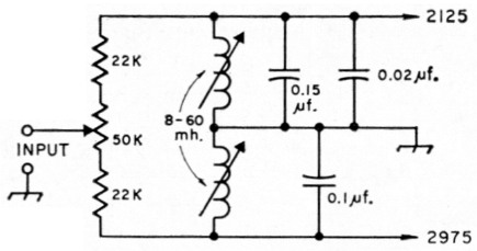
Fig. 2. The Mainline 5850 filter system for broad-band general reception. Bandwidth of the filters is about 300 cycles each. The coils are TV width coils (Miller 6319).
This is the broad-band TV-coil filter of the original Mainline TT/L, but updated slightly to provide output voltage comparable to that of the other filters. This will simplify quick switching between the various systems. The crossover frequency in the author's unit was 2554 cycles.
The "Mainline 8850" filter (Fig. 3)
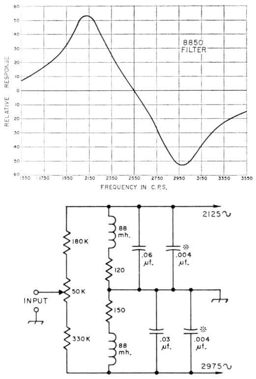
Fig. 3. The Mainline 8850 filter using 88 mH toroids. Short out the resistors in series with the toroids for maximum sharpness while tuning to frequency. The 0.004 µF capacitor values (marked *) are approximate because of copacitance tolerance variation. The 8850 is for general reception; filters are each about 300 cycles bandwidth.
This is a broad-band filter for 850 shift using 88 mH toroids. Its output voltage and general characteristics are similar to that of the TV-coil system (the 5850 filter), and it is intended for those who would prefer working with the 88 mH toroid to using the TV coils. The curve is one actually obtained from the author's TT/L with this filter in use. (The curve for the 5850 was so similar that it need not be published.) The 5850 and 8850 filters are each approximately 300 cycles wide at the -3 db. points. Center crossover for the 8850 filter was 2551 c.p.s. in the author's unit.
Curves were run on the mark and space filters in the 8850 filter system, and the bandwidths were found to be extremely well-balanced:
| Filter | -3 dB | -6 dB | -10 dB | -15 dB | -20 dB |
|---|---|---|---|---|---|
| 2125 | 313 | 508 | 945 | 1645 | 3122 |
| 2975 | 306 | 506 | 961 | 1668 | 3190 |
The "Mainline 7850" filter (Fig. 4)
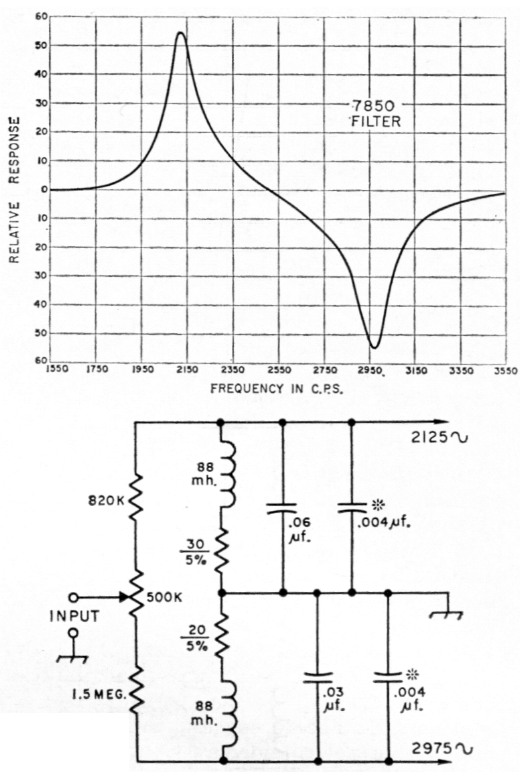
Fig. 4. The Mainline 7850 filter using 88 mH toroids. The 0.004 µF capacitor values (marked *) are approximate. Short out the resistors in series with the toroids for maximum sharpness while tuning to frequencies shown. This filter is primarily for limiterless reception of 850 shift. The filters are each about 85 cycles bandwidth.
This filter may be rather different from anything the reader has seen before. It has two filters that are simple and yet rather sharp - about 85 cycles each. The characteristics of the 88 mH toroid when used this way allow reception to some extent of shifts other than 850, but the filter is intended mostly for limiterless copy of 850 shift. It should interest those who do not wish to build the 3-pole Butterworth types which follow (three 88 mH toroids in each filter). This system may also be used for quickly setting the transmitter shift to a much closer tolerance than would be possible with the 5850 or 8850 filters.
The "Mainline 8170" filter (Fig. 5)
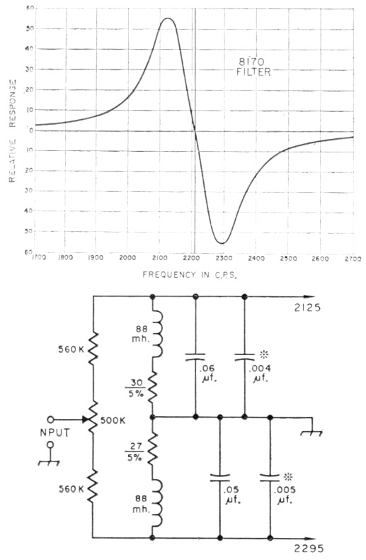
Fig. 5. The Mainline 8170 filter for 170 shift. Each filter is about 85 cycles wide using 88 mH toroids. Capacitor values marked (*) are approximate, and should be selected to tune the toroids to the indicated frequencies.
This is a narrow-shift filter (170 shift) and ha, bandwidths of approximately 85 cycles. It is nearly the same as that published in November QST,(4) with minor changes that allow more balance range. Center crossover on the author's unit was 2209 cycles with mark at 2125 and space at 2295.
Installing the "5, " "7" and "8" series filters
A quick glance at August 1965 QST, page 30,(1) will show how the original filter section of the Mainline TT/L was installed. Any of the filters just mentioned (the 5850, 8850, 7850 or 8170) can be installed in place of the one shown, or in addition to it, by using a 3-pole multi-position switch or plug-in containers. The switch is preferable, because exchanging the filter containers when going from one system to another destroys most of the value in building the filters in the first place - it is just too much effort to be continually exchanging the filters.
Notes
- Hoff, "The Mainline TT/L F.S.K. Demodulator," QST, August, 1965.
- Poor, "Filters for RTTY," RTTY, May, 1964.
- Hoff, "Checking RTTY Shifts " QST, May, 1966.
- Hoff, "Operating the RTTY Station," QST, November, 1965.
Part 1 - Part 2
Irvin M. Hoff. K8DKC.