A transmatch for balanced and unbalanced lines
Getting rid of your harmonic problem.
During 1965, over 7000 Novices received notices from ARRL Official Observers who had noted defects in the Novices' signals. Most of these notices cautioned the Novices that they were radiating a second harmonic of their 80-meter signal. A large number of these Novices were also cited by the FCC for harmonic radiation.
Certainly every Novice wants to have a clean signal, one with no spurious radiations. A newcomer, starting out in amateur radio, has to acquire considerable "know how" to put a clean signal on the air and this includes getting rid of harmonics. In this article, we'll tell you the "why" and "how".
Many amateurs are inclined to blame the manufacturer if his transmitter radiates a har monic. This is unfair because a manufacturer has no way of knowing how the amateur is going to use the equipment after he purchases the rig. It is quite possible that the same transmitter could be used on two different types of antenna systems and radiate a harmonic on one system and not on the other. The best approach to the problem is to assume that a harmonic or harmonics will be radiated by your transmitter and that something must be done to prevent this from happening.
Usually the reason we have harmonic radiation from a transmitter is because of insufficient selectivity between the final amplifier stage and the antenna. Installing additional circuits will attenuate any harmonics to the point where they would be no problem. In our opinion, the best approach for cleaning up this problem is to install a transmatch between the transmitter and antenna. A transmatch, in addition to providing the required selectivity for harmonic attenuation, has other important features.
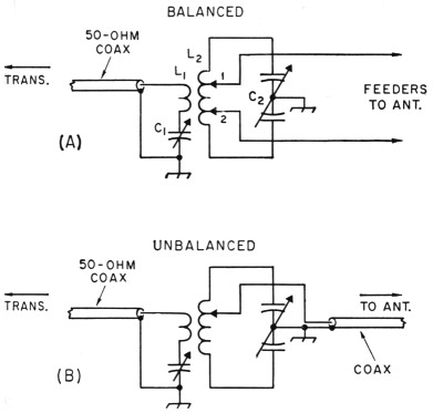
Fig. 1. At A isthe transmatch circuit for balanced feed lines and at B, for coaxial lines.
Nearly all transmitters are designed to work into 50- to 70-ohm loads. On the other hand, very few antenna systems will present such a load across an amateur band and, what complicates the problem, many transmitters have no adjustments in the amplifier to cope with loads other than 50 ohms. For such a transmitter to work at full efficiency the load must be 50-ohms. A trans-match takes care of this problem because it can be considered a "matching" circuit in that it takes the unknown load on its output side and makes it a 50-ohm load on the input side.
Another important advantage in using a trans-match is to provide additional selectivity for your receiver. In many instances, a nearby broadcast station will cause severe cross-modulation in a communications receiver, particularly to 80-meter reception. If you don't know what cross-modulation is it can best be described as a mess of confusing "garbage" across the band. The signal you want to copy, instead of being clean, is hashed up by the strong nearby broadcast signal (or any strong local signal for that matter). The transmatch usually will provide enough selectivity to keep the strong signal from cross-modulating. Don't misunderstand, this won't get rid of another local ham signal in the same band but it will help on strong local signals that are outside the band you are listening to.
Still another feature of a transmatch is that it provides harmonic attenuation in the TV range in addition to taking care of the lower-frequency harmonics. Also, if you must use a low-pass filter for maximum TVI harmonic attenuation, such a filter should be installed in coax line that has a very low standing-wave ratio so that the low-pass filter components won't be damaged by excessive voltages. The transmatch will provide a section of coax line with a low s.w.r., that portion between the transmitter and transmatch. All in all, one should see the desirability of using a transmatch. The transmatch described in this article can be used for unbalanced lines (coaxial) or for balanced lines (open-wire or Twin-Lead).
Transmatch and unbalanced lines
Fig. 1A is the basic circuit for a transmatch used with balanced lines, and Fig. 1B is for unbalanced or coaxial lines. Fig. 2 is the circuit diagram of the working unit.
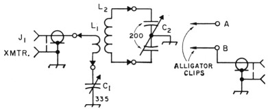
Fig. 2. Circuit diagram of the transmatch. Balanced feeders should be attached to A and B.
C1 335 pF variable (Millen 19335 or equivalent).
C2 200 pF dual variable, 0.077-inch air gap for 1 kW (Millen 16200), 0.022-inch air gap for 150 watts and less (Millen 28200).
J1,J2 Coax chassis fitting, SO-239.
L1, L2-See Fig. 3 and text.
Until recently, and by recently we mean the last few years, transmatches were not used with coaxial antenna-feed lines. The main reason for not using a transmatch was simply that coax is a line that should be matched in its characteristic impedance - or at least if it is not matched, the standing wave ratio should be kept as low as possible. Operating coax line with a high s.w.r. causes excessive losses in the line. However, transmitters and transceivers in recent years have come on the market without any provisions in their tank circuits to handle loads other than 50 ohms. When the s.w.r. is greater than 1 to 1, the load on the transmitter is something other than 50 ohms, and in many instances it becomes impossible to load the final amplifier. A transmatch makes it possible and, in addition, even though a multiband coaxial-fed antenna is used, the transmatch will take care of the ever-present harmonic problem. These are the reasons for using a transmatch in a coaxial-fed antenna system.
On the other hand, balanced lines such as open-wire or a good grade of 300-ohm twin lead are not lossy lines and they can be operated with a relatively high s.w.r. without any appreciable loss in efficiency. In the case of a high s.w.r. we are faced with the problem of matching a load that is quite far removed from 50 ohms. The trans-match will do just that because it is an adjustable matching device.
Getting the parts
It is becoming more and more difficult to find dealers who handle a wide range of useful amateur components, even among the larger mailorder houses. With the exception of the coil stock, all the components used in this trans-match are made by the Millen Co.(1) The coil stock is manufactured by Polyphase Instrument Co. and if your local distributor doesn't stock the coil material you can write the company(2) and they'll tell you where you can buy it.
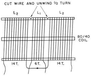
Fig. 3. Details for making the 80/40-meter coil. The 20-meter coil consists of 2 turns for L1 and 6 turns for L2 (3 turns on either side of L1). Details for the 15/10- meter coil are given in the text. The coils are mounted on Millen type 40305 plugs and the socket is Millen type 41305. Coil stock is Polyphase PIC type 1778, 3-inch diameter, 6 turns per inch, No. 12 solid wire.
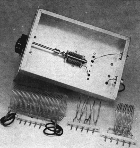
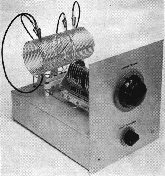
This shows the placement of C1 and also the three coils. Although the center pin of the coil sockets is not used for a connection, the "joined" portion on each side of the link (the two L2 sections) are soldered together and then connected to the center pin. This provides additional support to the coil assembly.
We've specified two types of capacitors for C2. The larger spacing will handle one kilowatt with most loads that will be encountered, while the smaller-spaced unit will handle up to 150 watts. There isn't enough difference in price between large and small coil stock, except size, so the builder is just as well off using the larger-size coil material for all power levels.
Construction
The transmatch is built on an aluminum chassis 3 × 8 × 12 inches, although any size chassis that will hold the components can be used. The dual variable, C2, is mounted on top the chassis and C1, the link capacitor, below deck. Mount the coil socket at least 2½ inches behind C2 so that the coil stock doesn't short to the metal frame at the rear of the capacitor. The coil socket is mounted on ¾-inch-high isolantite stand-offs, and 1½-inch-high standoffs are used for the feeder tap leads. A permanent connection is made from one of these standoffs to J2, the coax connector mounted on the rear of the chassis.
Three plug-in coils are required to cover the 3.5- through 28-Mc. bands, one serves for 80 and 40, another for 20, and a third takes care of 15 and 10 meters. A single length of the coil stock listed in Fig. 3 is all that is needed for the 80/40 and 20-meter coils. Coil stock is not used for the 15/10 coil.
Refer to Fig. 3 for details of the coil construction. This drawing shows how to make the two coils, L1 and L2, from a section of the coil stock. The coil shown is the 80/40 combination and construction of the 20-meter unit is similar.
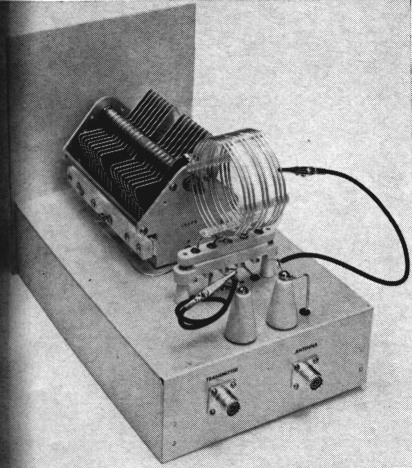
This shows the set up for use with a coax-fed antenna. The clip on the standoff on the right is topped onto 1.2. The other clip is clipped back on itself.
No. 12 solid wire is used to make the 15/10-meter coil. L2 consists of 4 turns, 3 inches in diameter, with the 4 turns spaced over 3 inches. Ll is a single turn of No. 12, 2 inches in diameter, mounted in the center of L2.
The 5-prong coil plugs have a nickel coating which should be filed off the ends of the prongs in order to get a good solder connection.
Tune-up and adjustments
In order to properly adjust a transmatch an s.w.r. indicator is a big help. Just recently in QST(3) a combination wavemeter and s.w.r. indicator was described. This is a very simple unit to make, and in addition to helping you adjust your transmatch, it will show you if you are on the correct band or not. Many newcomers make the mistake of tuning up their rigs on what they think is the correct band but actually end up outside the band. The unit mentioned, the Wave-bridge, will help prevent this.
Fig. 4 shows a typical station arrangement for connecting the different units together. If a low-pass filter is required it can be installed immediately after the transmitter if an antenna change-over relay is used. If a diode or tube-type t.r. switch is used, the low-pass filter should be installed after the t.r. switch as these devices are known to cause harmonic TVI and you would want to prevent harmonics from such a device from reaching the antenna. Also, if at all possible, connect a good earth ground to the transmatch. It will work without one but, if you can, put in a ground connection.
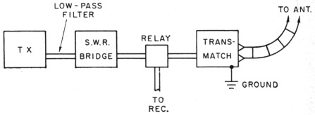
Fig. 4. This is a typical arrangement of units for a station installation. Coax line connecting the units together can be 50- or 70-ohm, depending on the s.w.r. bridge impedance.
Let's take the case of coax-to-coax, a coax-fed antenna. Connect the feeder to J2, tune up the rig on the desired band, and feed enough power through the s.w.r. bridge to get a full-scale reading with the s.w.r. meter switched to read forward power. Next, take the tap lead connected to the J2 inner conductor and tap onto L2 on either side of the link. It doesn't make any difference which side you tap on, but for a start put it on close to the link. Switch the s.w.r. bridge to read reflected power and then adjust C1 and C2 for a minimum reading of the s.w.r. meter. What you are shooting for is a reading of zero for reflected versus full-scale forward. This would indicate a 1 to 1 match and the transmitter would "see" a 50-ohm load. Also, you'll find several tap points with the tap lead that will give a match, but the one you want is with the tap as far out from the link, towards the outside end of L2, as possible.
For balanced feeders, connect the feeders to the two stand-off insulators and the tap leads to L2 on either side of the link. Also, if you happen to have two antennas, one with coax feed, don't leave the coax line connected to J2 when using the balanced feeders.
Using the s.w.r. bridge the same way as with coax feeders, shoot for zero reading on reflected versus full-scale forward. Also, as with the coax tap, keep the taps as far out from the link as possible. The taps should be equally spaced from the link; in other words if one tap is 534 turns from the link, the other one also should be 5% turns. If it is impossible to get a match it means that the load presented by the feeders is so reactive the transmatch cannot handle it. You can try adding some feeder length (or shortening the feeders) as this will present a different load and may well bring it within the range. However, this will only happen in extreme cases as the transmatch will handle a wide range of loads.
As we said at the beginning, a transmatch will keep you out of trouble and improve the operation of your station. Build one and learn how to use it.
Notes
- If you cannot obtain the parts from your distributor they can be purchased direct from Millen Co. Write to Janes Millen Manufacturing Co., Attn. Wade Caywood, W1KRD, Malden 48, Mass.
- Polyphase Instrument Co., Att. Tom Consalvi, East Fourth St., Bridgeport, Pa. 19405.
- McCoy, "The Wavebridge," QST, July, 1966. This issue of QST is available at ARRL Headquarters for 60 cents.
Lewis G. McCoy, W1ICP.