Building a simple crystal V.F.O.
This neatly-packaged 40-meter VXO provides a source of frequency control whose stability approaches that of a crystal oscillator. WSQ LV shows how a minimum number of parts can be put to use in a practical circuit. This basic design can be followed when building a similar unit for 80 or 20 meters. The v.h.f. man should find this circuit useful when building an 8- or 12-Mc. VXO.
The crystal frequency synthesizer combines the extreme stability of the crystal oscillator with the continuous variability of the ordinary v.f.o., hence would seem to be almost ideal for the master oscillator in amateur transmitters. One major obstacle is the complexity of the circuits. The other is cost.
Many stations are operated in narrow segments of one or two bands. This type of operation does not require a wide-band synthesizer, but does require continuous variability within a narrow band. Such a requirement is met economically by the simple crystal v.f.o. to be described. In any case, whether a simple crystal v.f.o. or a sophisticated synthesizer is used, the cost will be lowered if the number of crystals can be reduced. This leads to an analysis of the problem of "pulling" crystal oscillators with an eye to maximizing the deviation.
Some considerations
The author discovered that the circuit capacitances used in common crystal oscillators are much too large to achieve maximum deviation using either the FT-243 or the HC-6/U crystal. The latter unit has the higher capacitance and is therefore preferred. The problem can be solved either by designing an oscillator having exceptionally low minimum shunt capacitance, or by persuading the crystal makers to produce special units having larger capacitance. Until that happy day arrives, the former alternative must be pursued.
In order to keep the minimum capacitance down, it is necessary to eliminate the crystal selector switch. The oscillator shown in Fig. 1 (but without the switch) has a minimum capacitance which must be less than the crystal socket capacitance plus the minimum capacitance of one section of the split-stator capacitor, C1, and the input capacitance of the tube. The maximum capacitance will be only somewhat less than the crystal socket capacitance plus half the maximum capacitance of one section of C1. The optimum value of crystal capacitance for this circuit (without a crystal switch) is about 12.4 pf., whereas the capacitance of HC-6/U crystals is about 7 pF. The deviation calculated for the HC-6/U crystals comes out to be 7.63 kc., a figure which has been verified experimentally. This is about 95 per cent of the deviation obtainable from a crystal having the optimum capacitance, so not much is to be gained by the use of special crystals in this circuit.
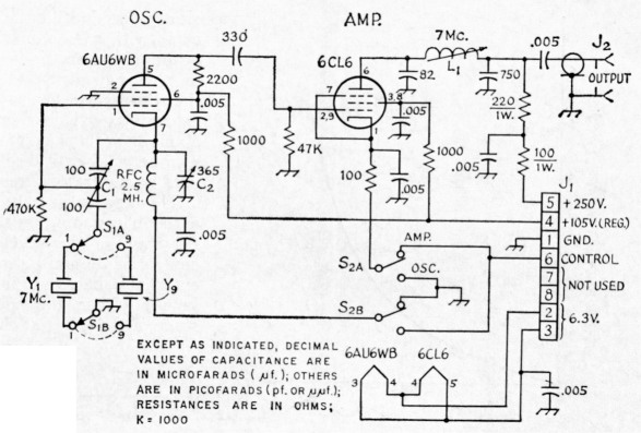
Fig. 1. Circuit of the crystal v.f.o. Fixed capacitors are disk ceramic. Resistors are I/2-watt composition unless otherwise noted.
C1 100 pF per-section dual variable (Hammarlund HFD-100 or equal).
C2 365 pF variable (midget broadcast type suitable).
J1 8-pin male chassis connector (Amphenol 86-CP8 mounted in Amphenol 61-61 shell).
J2 Coax connector (SO-239 type).
L4 18 turns No. 22 enam. wire close-wound on 11/16-inch diam. slug-tuned form (approx. 5 µH min. inductance).
S1 Epoxy rotary, 2 sections, 2 poles, 12 positions, 10 positions used. IRC 1315 used. (Also, see text.)
S2 D.p.d.t.toggle switch.
Y1-Y9, incl. 7-Mc. crystals selected for desired frequency of operation (in HC-6/U holders; see text).
It should be possible to mount the crystals in an insulated turret so as to facilitate frequency changing without adding to the shunt capacitance. This arrangement would produce deviations of 7 kc., so that a turret using standard 30-degree indexing would carry 12 crystals, covering a range of 84 kc. on 40 meters.(1) The machining problem was considered too formidable for most constructors, so it was decided to use a standard switch and sacrifice some of the range.
The author selected a small 12-position 2-deck rotary switch and soldered the crystal sockets directly to the switch terminals. The switch was then mounted on an insulating bracket so as to minimize the shunt capacitance. The resulting deviation is a little over 5 kc. on 40 meters.(2) In this model, 10 crystals are used to achieve a range of 50 kc. adjacent to the lower band edge.
A typical calibration curve is shown in Fig. 2. The linearity could be improved by the use of "mid-line" plates, but the available capacitors having this plate shape have a larger minimum capacitance and a smaller capacitance ratio, both of which will reduce the range.
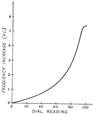
Fig. 2. A curve showing the typical change in frequency in kilocycles as CI is tuned through its range. The curve is for the circuit of Fig. 1.
The Circuit
In addition to producing very low minimum capacitance, the split-stator capacitor adjusts the circuit gain upward as its capacitance is decreased. This increase in gain tends to keep the oscillation amplitude constant as the capacitor is rotated.
The 6CL6 is a power amplifier and its tank circuit affords a fair match to 50-ohm coaxial cable. The output is quite uniform at 3 r.m.s. volts over the full 50-kc. range when directly feeding a 47-ohm resistor. Provision is made for keying either the oscillator or the amplifier by selecting the position of S2.
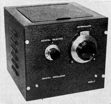
The mechanical construction should be clear from inspection of the photographs and their captions. The unit is housed in a 7 × 8 × 8-inch cabinet (Bud C-973).
Testing
After the wiring is completed, connect an r.f. voltmeter, having a 10-volt peak scale, to the output fitting, and terminate the output with a 47-ohm resistor. (Such a circuit is shown in Fig. 3.) Set capacitor C1 to mid-range, adjust C2 to maximum capacitance, then apply power. Next, tune the coil slug of L1 for maximum r.f. output, which should be about 4 volte peak. Now, the tuning of C1 through its range should not affect the output voltage appreciably. If the oscillator quits, decrease the capacitance of C2 somewhat until the oscillator will "stay in business" across the full range. If this fails, try another tube.
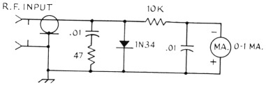
Fig. 3. Circuit of a dummy load and r.f. voltmeter that would serve as a test unit for the VXO. Both 0.01 capacitors are in µF and are disk ceramic. Resistance is in ohms (K = 1000). Resistors are ½-watt composition.
The keying switch, S2 (Fig. 1), routes the cathode lead of either the oscillator or the amplifier stage of the VXO to Pill 6 of J1. Remote control of the unit is made possible by shorting, externally, between Pills 1 and 6 of J1. S2 permits keying either the oscillator or the amplifier stage of the VXO at the operator's option.
Operation
This unit is intended to be used as a replacement for a conventional v.f.o. The power requirements are 6.3 volts at 1 amp., 105 volts regulated at 10 milliamperes, and 250 volts at 25 milliamperes. The v.f.o. output should drive the crystal oscillator or v.f.o. input of any transmitter by simply terminating the far end of the connecting cable with a 47-ohm resistor and using an appropriate connector to mate with the connector on the transmitter. If more voltage is desired, the resistor can be removed and the coil slug of L1 readjusted for resonance. This should give about 10 volts peak. If still more drive is needed, a pi network or a resonant transformer may be used at the transmitter end of the cable.
Performance
The frequency stability of this oscillator hit, been checked while using the CMC 800A Frequency Counter with 802A and 831A plug-in units. The drift observed from a dead-cold start was plus 16 c.p.s. for the first hour, followed by about minus 2 c.p.s. per hour for the next six hours. Then it settled down. The drift does not change appreciably from these figures for any combination of crystal and capacitor positions.
The author has used this unit side by side with a wide-band frequency synthesizer. Where it can be used, the simple VXO is preferred because it is more stable and has absolutely no spurious output.
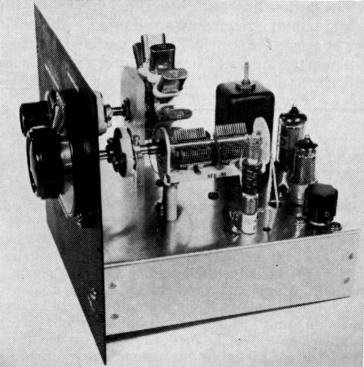
Top-chassis view of the VXO. C1 is in the foreground. L1 is mounted inside the shield can at the far right of the chassis. The crystal-selector switch is located on the far side of the chassis. Both CI and SI are mounted on insulating material. The knob for C2 is at the lower right of the chassis.
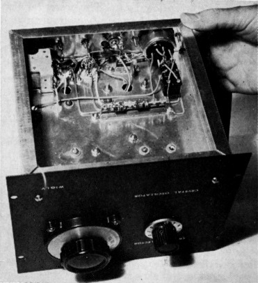
Bottom side of the VXO chassis. The keying switch, S2, is in the upper right corner of the chassis. C2 is in the upper left corner.
- A turret switch of this design is available on special order from Mr. Howard Chapman, 519 Yale Ave., Baltimore, Maryland 21229.
- The crystals are type HC-6/U and are designed to work into a 32-pf. circuit. (Available from Texas Crystals, 1000 Crystal Drive, Fort Myers, Florida.)
Frank W. Noble, W3QLV.