Evolution of a grounded-grid amplifier
Although grounded-grid operation has its virtues, the author points out that the simplicity popularly associated with this type of circuit may not always be one of them. He discusses some of the problems involved in the design of his own amplifier.
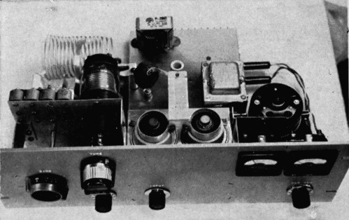
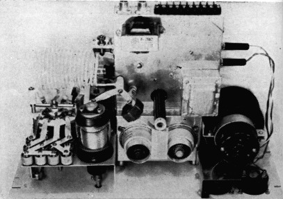
Panel controls, from left to right are, plate band switch, output tuning capacitor (above) and loading control (below), input band switch, and a.l.c. biasing potentiometer. This view also shows the tube plate connections.
A really simplified approach to building a a linear amplifier is to use a grounded-grid circuit. All that is needed are tubes, a tank circuit, and a power supply," it has been said, and some commercial and ham-built amplifiers use this concept. However, not all types of tetrodes lend themselves to such cavalier treatment.
The amplifier shown in the photographs was designed around a pair of 4CX300A tetrodes, although the general principles to be discussed will apply equally to other tubes of this family, such as the 4X250 and 4X150, or their CX counter-parts. Tubes in this series were selected because they are small, rugged, and are often reasonably priced on the "new surplus" market. Thy also have the advantage of a cathode not connected to the heater, and therefore they can be used in the grounded-grid configuration without the need for filament chokes or a low-capacitance heater transformer.
However, they cannot be used as high-p zero-bias triodes, with the control grid and screen tied together and grounded, as can some other types, because the control grid tends to hog most of the drive and its dissipation ratings are exceeded long before rated output is achieved.(1) This condition can be avoided by grounding both elements for r.f. through bypass capacitors, but operating them at their normal d.c. potentials. This was not considered to offer any serious problem.
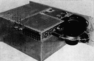
The completed amplifier (inverted) with shielding in place.
Since experience seemed to indicate that the pair of tubes would show an input impedance in the vicinity of 50 ohms, the amplifier was fed directly with RG-8/U coax line.
Upon completion of the construction, initial tests were made using 2500 volts on the plate, regulated 360 volts on the screen, - 55 volts of bias on the grid, and a two-tone input signal. Everything seemed to be working fine until operation was carried down to 15 meters. On this band, r.f. feedback caused very unstable operation. In the simple input coupling system being used, the tube, output tank, and excitation source are in series. The r.f. output current has to return to cathode through the exciter output coupling system and the coax line. Although the line was shorter than the Rio wave-length usually considered permissible, the reaction was there. And then, too, the exciter output circuit was not designed to carry the additional r.f. current, some 2 amperes in this case. A quarter-wave line could have been used, but this would have meant a separate line for each band, and switching five lines doesn't lend much to rapid band changing.
There went the first simplification. A tuned circuit had to be added. Now, the excitation voltage is developed across this input circuit, and the return current is confined to a short direct path within the amplifier itself. Veryhigh-C input tanks are used. These are pretuned W the center of each band with the aid of a grid-dip oscillator. They work very well across the phone portions of the bands without readjustment. The fly-wheel effect of these tanks also improves the regulation of the driving signal, reducing the distortion that is likely to occur, because of changes in amplifier input impedance over the driving cycle, when a simple random length of coax is used to feed the amplifier.(2)
The next problem to be encountered was to find that the amplifier was not linear out to the required 500 ma. of plate current. On bringing up the drive, a knee appeared in the scope trapezoid pattern(3) at about 375 ma. with optimum loading. When the loading was increased so that the output dropped 20 per cent, the knee was pushed out to 400 ma.
Super-cathode drivel was then tried. In its simplest form, this arrangement is the same as the high-0 zero-bias triode connection mentioned earlier, but with the grid tapped up from ground on the input tank. This reduces the drive to the grid, while maintaining full drive to the screen. The tap can be adjusted to limit the drive to a level that will keep the grid dissipation within rating. To assure this, the tap was placed far enough up on the input coil so that the grid current would not exceed the rated Class C value with full drive applied.
With this modification it was found that the amplifier could now be driven to a plate current of 600 ma. before flat-topping. However, considerably more drive was required for full output. Drive requirements were reduced to a more reasonable level by the use of a small amount of screen voltage. This also required some grid bias to place the operating point at the most linear portion of the tube curve. The slight concavity in the trapezoid pattern that had appeared uncorrected with the zero-bias connection was also rectified by the introduction of a suitable value of grid bias.
Circuit
The final circuit that emerged from these tests is shown in Fig. 1. The high-C input tank circuits are selected, according to the band in use, by the double-pole switch S1. A band-switching pi network is used in the output circuit. The amplifier is switched in and out by relays K1 and K2. A second pole on K1 (Kin) switches the amplifier grid to cutoff bias to let things cool down on standby and it also eliminates diode noise while receiving.
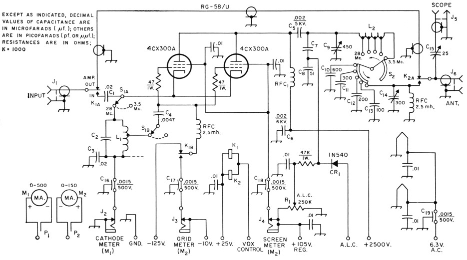
Fig. 1. R.F. and control circuitry of K4ZZV's grounded-grid amplifier. Except as indicated otherwise in the diagram, or listed at the left, fixed capacitors of decimal value are disk ceramic, 1000 volts.
C1,C3 Two 0.01-µf. mica capacitors in parallel.
C2 Mica, see table for value.
C4,C8 Mica.
C5 Transmitting-type mica (CornellDubilier type 9H).
C6 Disk ceramic, 6000 volts.
C7 Fixed air capacitor, see text for construction.
C9 3000-volt variable, see text.
C10-C13, incl.-Capacitances made up of 100-pf. 5000-volt ceramic capacitors (Centralab 8585-100N) in parallel as required. See text.
C14 Receiving-type variable (National TMS-300, Hammarlund MC-325, or similar).
C15 Air trimmer.
C16-C19, incl.-Feedthrough capacitor. Used between amplifier and power-supply chassis.
J1,J6 Chassis-mounting coaxial receptacle.
J2,J3,J4 Closed-circuit jack.
J5 R.F. type phono jack.
K1 D.p.d.t. 24-volt d.c. relay (Jennings RB-3, Guardian 1200-2C-24A, or similar).
K2 Similar to Ki, s.p.d.t.
L1,L2 See table and text.
M1,M2 D.C. milliammeter, see text in reference to M2.
P1,P2 Headphone plug.
R1 Linear control.
RFC, R.f. choke from ART-13, replacement for choke in 32V, or Raypar RL-100.
S1 Two-section, four-pole 5-position ceramic rotary switch. (Centralab 2515), poles and corresponding-position contacts connected in parallel on each wafer.
S2 Replacement switch for HT-33, see text.
Provision is made for metering grid current, screen current and cathode current. A system of plugs and jacks is used to make connections to the two meters, which are mounted on the panel, but exterior to the amplifier enclosure. A 500-ma. meter is used to measure cathode current. The other meter has a 150-ma. scale, and may be plugged in to read either grid current or screen current. The zero-set screw of this meter is adjusted to give a deflection of 20 ma. with no current flowing through it. This is to take care of reverse screen current, which is normal under certain conditions.
This view shows the metering jacks, and the construction of the a.l.c. coupling capacitor C7.
Relay-voltage and low-impedance adjustable bias supplies are built into the amplifier unit. The circuits of these supplies are shown in Fig. 2. Other supplies (105 volts regulated for the screens, and 2500 volts for the plates) are external. A VR-105 is used in the screen supply, and its series resistor is adjusted for a VR-tube current of 40 ma. without load.
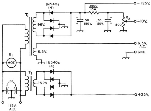
Fig. 2. Bias and relay-power circuits. Capacitances are in µf.; resistances are in ohms. Capacitors of decimal value are disk ceramic; others are electrolytic. Diodes are 400 p.r.v., 750 ma.
B1 75 c.f.m. blower.
R2 Wire-wound control.
T1 Power transformer: 96 volts, r.m.s., 40 ma.; 6.3 volts 6 amperes (Merit P-3044).
T2 25.2-volt 1-ampere filament transformer (Merit P-2962).
Included also is an automatic load-control circuit. A small amount of r.f. is coupled out of the output circuit, rectified by CR1, and fed back to the a.l.c. input of the exciter. The a.l.c. adjustment potentiometer, R1, applies reverse bias to the diode to control the amplitude of the a.l.c. signal.
Construction
While it is probable that not many will want to duplicate the amplifier shown in the photographs in all mechanical details, constructional points will be reviewed briefly. The tubes and input-circuit components are mounted on and in a 4 × 6 × 3-inch aluminum chassis which is mounted from the 7 × 19 × 3/16-inch panel on spacers. One side of the chassis is cut out to fit the exhaust flue of the blower.
A 7 × 7 × 2-inch chassis accommodates the relays and components of the bias and relay supplies. The components of the pi network are mounted on a L-shaped subpanel attached to the amplifier-tube chassis and to the panel, using spacers about 2 inches long for the latter.
Copper strip is used for connections in the output circuit. Referring to the photographs, one end of a wide strip joins the two wrap-around anode clamps. The other end of this strip goes to the top end of the plate-circuit r.f. choke, RFC1. A narrower (½-inch) strip attached to the same terminal of the choke supports one side of the blocking capacitor C5. The other end of the capacitor is supported by a short ½-inch-wide strip attached to a 2-inch ceramic pillar. Capacitor C7 is formed by attaching a length of ½-inch strip to the top of a ceramic feedthrough insulator mounted in the power-supply chassis, immediately below C6. The strip is bent so that ¾ inch of its length runs parallel to the capacitor to-pillar lead, and spaced 1/8 inch from it. The lower terminal of the feedthrough insulator is connected to C8 which is mounted inside the chassis. The 2-inch ceramic pillar also serves as a tie point for the tank coil and tuning capacitor C9.
The vacuum capacitor, plate band switch, and the fixed loading capacitors are mounted on a subpanel. There is a total of 12 fixed capacitors, each having a capacitance of 100 pf. Units are strapped in parallel, as necessary, to provide the capacitance values shown in the circuit diagram. Variable capacitors C14 and C16 are mounted on a side apron of the power-supply chassis. The latter may be adjusted with a screwdriver from the rear.
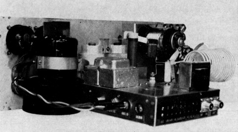
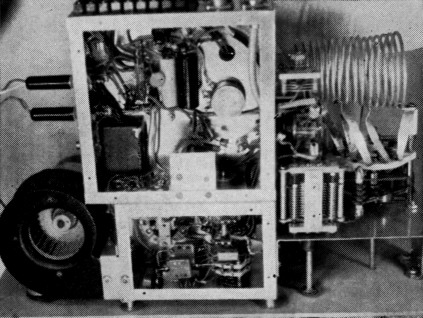
Rear view showing the general layout of components. Bandswitch connections to the fixed output capacitors may be seen at the lower left.
The plate band switch, S2, was salvaged from an HT-33. It exactly filled the bill for the author, but those who wish to build a similar amplifier may have to improvise if they can't dig up something similar. A heavy-duty switch, such as one of the new Millen units,5 might be used for the coil. It is not strictly necessary that this switch be progressively shorting. If a nonshorting switch is used, the arm should be connected to the output end of the coil, and the contacts to the taps in conventional fashion. A smaller progressively-shorting switch, such as the Centra-lab PISD ceramic wafer with matching index assembly, should he adequate for switching the fixed loading capacitors.
The tuning capacitor (C9) in the photographs is a vacuum unit (similar in ratings to the Jennings UCSF-500) having a maximum capacitance of 450 pF. However, the capacitance needed to tune to the 75-meter band with the coil inductance specified for L2 is approximately 250 pF. If space is available, a standard air variable having a maximum capacitance of this value (such as the Johnson 154-9) should be suitable.
| Band | C2 | L1 - turns | L2 - µH |
|---|---|---|---|
| 4 Mc. | 0.01 µF | 5 | 8 |
| 7 Mc. | 0.0047 µf. | 4 | 4 |
| 14 Mc. | 0.0027 µF | 2 | 2 |
| 21 Mc. | 0.0011 µF | 2 | 1.25 |
| 28 Mc. | 620 pF | 2 | 1 |
See text for other details.
Coils
The input coils are wound on a form ½ inch in diameter, using No. 14 wire. After removing each coil from the form, the proper fixed capacitor should be soldered directly across the coil. The spacing of coil turns should then be adjusted until a grid-dip meter indicates resonance at the center of the desired operating range. These coils are supported between the switch terminals and a common tie point.
The pi-network coil was wound with No. 8 wire on a mandrel tapering from 3 inches o.d. to 2_1/8 inches to give a better form factor on the higher-frequency bands. A few extra turns were wound on the form at the start. After guesstimating the spacing, a grid-dip meter, a fixed capacitor of known value, and an LC chart were used to locate the taps to give the inductance values shown in the table. In this instance, the coil has a total of 16 turns, with taps at 5, 9, 10¾ and 12 turns from the output end, the large-diameter end of the coil being the output end. If preferred, heavy-duty variable-pitch coil stock may be substituted, using the same method to determine the tap positions.
The tap leads are of ½-inch copper ribbon. After soldering these leads to the coil, the whole assembly was silver-plated to give it a "commercial" appearance. All other copper connecting strips and clamps were given the same treatment.
Adjustment
The general objectives in adjustment are to set the grid tap on the input circuit at a point that will limit the grid dissipation to within rating, use sufficient screen voltage to reduce the driving-power requirement to a reasonable value, and adjust the grid bias for best linearity. These adjustments are not entirely independent of each other, or in respect to loading, and considerable time was required to arrive at the combination that was finally used. In the amplifier described, the grid is tapped down from the cathode about of the total number of turns in the input coil for each band. Screen voltage is regulated at 105 volts, while the bias is set at approximately - 10 volts. The adjustment of bias is rather critical. A few per cent either way can bring the distortion products up fast. The scope may be left connected for on-the-air monitoring. These adjustments resulted in a grid current of 10 ma. when the amplifier is driven with a two-tone test signal to a point just below flat-topping - plate current about 600 ma. The zero-signal current is about 225 ma. Methods of checking overall linearity and distortion are covered in the A.R.R.L. Handbook and will not be repeated here.
The a.l.c. control should be adjusted to bias off the a.l.c. diode until the amplifier is fully loaded. Then the bias should be backed off until the cathode meter kicks up to peaks of about 350 ma. on average speech.
Bottom view showing the coil taps, variable output capaciter and the scope coupling capacitor. The input band switch and the input-circuit components are assembled inside the small amplifier-tube chassis, bottom-center.
Notes
- Welch, Technical Correspondence, QST, April, 1959, p.46.
- Orr, Rinaudo, Sutherland, "The Grounded-Grid Linear Amplifier, QST, August, 1961.
- In this instance, the trapezoid pattern is used to check plate linearity only. It will not indicate possible distortion of the driver signal by nonlinear loading of the input circuit caused by changes in amplifier input impedance over the driving cycle.
- Single Sideband Principles, Pappenfus, Brume and Schoenike, pp. 159, 193. McGraw Hi14
- New Apparatus, QST, July, 1966, p. 29. Bottom view showing the coil taps, variable output capacitor and the scope coupling capacitor. The input band switch and input-circuit components are assembled inside the small amplifier-tube chassis, bottom center.
Wayne W. Cooper, K4ZZV/W6EWC.