Small, high-efficiency loop antennas
An alternative antenna for small spaces.
The small loop antenna is akin to an uncut diamond. It has been around a long time, and has only recently been cut and polished to reveal a shining new gem. This antenna is small, operates well when mounted at ground level, and exhibits performance that competes with almost any HF antenna except a multielement beam at a wavelength or more above ground. This article explains how the wrapper was taken off this antenna, and why.
History
The so-called "Army Loop" antenna was the first effective implementation of a small loop for transmitting.(1) It performed well, in spite of poor efficiency, but efforts to duplicate the design for amateur operation failed.(2) Antenna Research Associates developed the loop into an excellent small communications antenna and patented it in 1967, and Technology for Communications, International (TCI) also developed a version. Both companies have marketed the units at a price tag exceeding $13,000 including automatic tuner. My efforts have been directed to developing a small practical antenna that any ham can duplicate.
I was searching for a small antenna design to help hams with restricted space, and concluded that the loop was one feasible approach to achieve high efficiency in a small space. Small antennas are characterized by low radiation resistance, and the addition of a loading coil adds losses that result in poor efficiency. If a large capacitor is added to a small antenna to bring it into resonance, and the antenna conductor is bent to connect the two ends to the capacitor, a loop antenna is formed. If the losses in the conductor are small and there are no losses in the capacitor, a high-efficiency antenna can be achieved in a small space. The amount of losses that could be tolerated was unknown; therefore, I developed a set of equations to allow the various parameters to be calculated. Once that was done, the other problems were easily solved.
Small-loop definition
A small loop is defined as an antenna in the shape of a loop with a conductor length (circumference) less than one-third of a wavelength. It will produce a radiation pattern that compares to a doughnut (see Fig 1). If the doughnut is standing on the ground with its axis horizontal, there will be a null through its center (on its axis). A unique feature of the loop is the radiation polarization. First, consider the straight dipole. The polarization of the straight dipole is taken to be the direction of the electric field, which is parallel to the axis of the dipole-no electric field or polarization exists in any other direction. If we bend the dipole into a circular loop having a single plane, the only polarization component radiated by the loop lies in the plane of the loop. However, in this plane the polarization component radiated from any given point on the loop is parallel to a line tangent to the loop at that point. Consequently, if the plane of the loop is oriented horizontally, the polarization will be horizontal everywhere-no vertical component exists because no polarization component exists outside the plane of the loop.
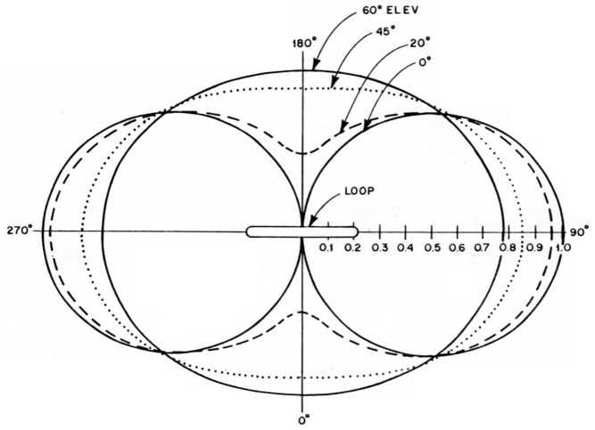
Fig 1 - Radiation pattern of a loop antenna.
On the other hand, if the plane of the loop is oriented vertically, the tangent line at the point of 0° in elevation is vertical, yielding vertical polarization. At the point of 90° in elevation, the tangent line is horizontal, yielding horizontal polarization. However, at all points in the loop plane between 0° and 90° in elevation, the tangent line is at an angle between vertical and horizontal, yielding a linear polarization comprising both vertical and horizontal components. For example, at 30° elevation the polarization angle is 600; at 45° elevation, the polarization is at 45°, and so on. The fact that it radiates at vertical and horizontal angles allows the benefits of both vertical and horizontal dipoles to be realized.
Mathematical equations used to define the loop
The equations I developed to define the loop follow.
Radiation resistance, RR, ![]()
Loss resistance, RL, 
(Eq 3)![]()
![]()
Inductive reactance, XL, ![]()
Tuning capacitor, CT, =![]()
Quality factor, Q, ![]()
Bandwidth, ![]()
Distributed capacitance, CD, = 0.82 S
Capacitor voltage, ![]()
where
A = area of loop (sq ft)
S = length of conductor (ft)
F = operating frequency (MHz)
D = diameter of conductor (in)
P = transmitter power (W)
Efficiency
Efficiency is defined as the power radiated by the antenna divided by the power applied to the antenna. Power applied to the radiation resistance will radiate, while power applied to the loss resistance will be converted to heat. Radiation resistance is a function of the area of a loop. For a conductor of given length, a round loop will have more area, hence a higher radiation resistance than any other shape. When mechanical factors are considered, an octagon loop is the preferred shape. A loop will have a radiation resistance approaching 0.05 ohm; therefore, loss resistance must be kept low. A loop made of ¾-in-diameter copper pipe is a reasonable compromise if the circumference is greater than 1/8 wavelength. Loops with circumference less than that require larger conductors. Table 1 shows recommended loop sizes for various frequencies.
| Circumference (Feet) | Frequency (MHz) | Efficiency (Below 100%) (- dB) | Tuning capacitor (pF) | Bandwidth (kHz) |
|---|---|---|---|---|
| 8.5 | 29 | 0.4 | 9 | 109 |
| 24 | 0.7 | 9 | 55 | |
| 21 | 1.0 | 23 | 36 | |
| 18 | 1.6 | 35 | 22 | |
| 14 | 3.1 | 60 | 12 | |
| 10 | 6.5 | 125 | 7 | |
| 20 | 14 | 0.3 | 6 | 66 |
| 10 | 1.0 | 29 | 20 | |
| 7 | 2.7 | 73 | 7 | |
| 38 | 7.2 | 0.5 | 10 | 27 |
| 4.0 | 3.0 | 102 | 5 | |
| 3.5 | 4.1 | 143 | 4 | |
| 60 | 4.0 | 1.0 | 23 | 10 |
| 3.5 | 1.5 | 47 | 7 | |
| 2.0 | 5.8 | 255 | 2 | |
| 1.8 | 7.0 | 328 | 2 | |
| 100 | 2.0 | 2.1 | 88 | 4 |
| 1.8 | 2.7 | 128 | 3 | |
| Notes | 1 All of the above use ¾-in copper tubing. | |||
| 2 Values of efficiency and bandwidth without radials. | ||||
Frequency range
The inductance of a loop can be calculated and the inductive reactance determined. The value of tuning capacitance that resonates the loop at a given frequency can then be calculated. I constructed several loops and measured them to find a value for the distributed capacitance. An equation was then empirically developed to define the distributed capacitance for any size of loop. Then, by subtracting distributed capacitance from tuning capacitance, we can determine the actual value of tuning capacitor required. With a large variable capacitor, a loop can be tuned to operate over a wide frequency range. The highest operating frequency of a small loop is determined by self-resonance, and the circumference must be less than ¾ wavelength. A 2:1 frequency range is reasonable for a loop-for example, a 14- to 30-MHz loop won second place in the ARRL Antenna Design Competition.(3)
Bandwidth
Here's the bad news-the loop is the equivalent of a high-Q tuned circuit, which means it has a narrow bandwidth. We can tune the loop over a wide frequency range, but the instantaneous bandwidth at the operating frequency will be low. At the lower design frequency of the recommended loops, the Q may be as high as 1000 and, therefore, the bandwidth is measured in kilohertz. This means you will need a remote motor drive on the tuning capacitor to shift frequencies. It's a low price to pay, and the only shortcoming of the loop antenna. You are simply trading bandwidth for size-you don't give up any other performance parameters.
The bandwidth can be calculated from the equations. After building your loop, it is important to measure the actual bandwidth. Comparing the measured value to the calculated value will tell if you did a poor job of construction - it will be apparent. Any metal in close proximity to the loop will absorb radiation and reduce the efficiency. This will become apparent from the bandwidth measurement.
Choosing the tuning capacitor
A high-Q antenna also means a high voltage on the tuning capacitor. An air gap of one inch in air is good for about 75,000 V. A power input to the antenna of 500 W will produce voltages of up to 30,000 V, so you need a capacitor spacing of ½ inch (¼ in for 100 W). The ideal capacitor for this application is a high-voltage vacuum variable, if you can afford one. Using a conventional variable capacitor will make the antenna useless because of the losses in the wiper contacts. This was one dilemma I ran into during development of the antenna. Then, late one night, I realized that a split-stator capacitor has no wiper contacts. If you connect each side of the loop to the stators, the RF coupling is through the rotors - no wiper contacts - and the spacing is effectively doubled since the two sections of the capacitor are in series. Now you have an inexpensive capacitor with no wiper contacts. However, you will not get the low losses and high efficiency unless the plates are welded together. No mechanical contacts are allowed! This means that you cannot use a capacitor with mechanical spacers between the plates unless a conductor is welded to electronically bond the plates. A local welding shop can do the job for you. (Note: The amateur version of the "Army Loop" used wiper contacts in the tuning network - now you know why it didn't work.)
If you need a fixed capacitor to parallel the variable, make one of printed-circuit board material. The value of capacitance can be determined from: C = 0.225 (N - 1) A/D, where N is the number of plates, A is the area of a single plate in square inches and D is the spacing in inches. Remember that you need a 30,000-V rating for 500 W - ½-in spacing for a high-Q loop.
A broadband matching network
The next step is to build a matching network to allow us to put power into the loop. Some builders use a coupling loop, but such a method is very critical. The amateur "Army Loop" used a very inefficient network. The easy way turns out to be the best - a simple form of gamma match that does not use reactive components. A piece of ¼-in copper tubing is soldered to the loop and to the coaxial cable connector (see Fig 2). A perfect match can be achieved by bending the tubing, and if the match is made at the center frequency of the loop, the SWR will be 2:1 or less over a 2-to-1 frequency range.
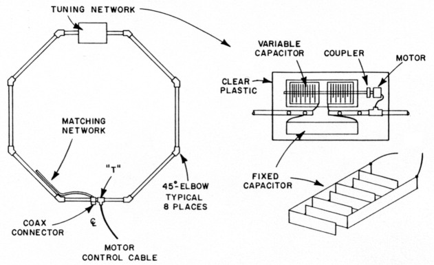
Fig 2 - Construction details for the recommended loops.
A remote motor drive
There isn't space in this article to cover all the details, but take it on faith that you need a stepper motor with a gear drive to give adequate tuning resolution. The computations are left to you. (Hint: A 10-foot loop will have a 14-kHz bandwidth at 14 MHz. A 50-pF capacitor can tune over a 16-MHz range with 180° rotation.) A possible answer is a motor, part no. 3004-001, and controller, part no. 22001, available from Hurst Manufacturing Co, Princeton, IN 47670. The cost of both units is about $90. The controller is an integrated circuit that requires a speed potentiometer, control switches and a 12-V source.
Loop construction
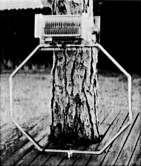
Fig 2 shows construction details for the octagon loop. The octagon shape is easy to construct using 45 ° elbows, available at any plumbing store. Just determine the size of your loop and cut eight equal-length pieces of copper pipe to total the circumference. Solder all lengths with 45 ° elbows to form the octagon. Make a cut in one side of the loop and install a copper T. Split and flatten a 3-in piece of pipe to make a mount for the coaxial-cable connector and solder it to the loop next to the T. On the side opposite to the coaxial connector cut out a section about two inches long. Mount a clear piece of 1/4-in-thick plastic sheet to the gap and mount the tuning capacitor, motor and a high-voltage coupler for the capacitor on the plastic. Install another T about 6 inches from the capacitor/motor and run the control cable from the lower T to the upper T inside the copper pipe - in one T and out the other. Connect the tuning capacitor stators to the ends of the gap with pieces of copper strap soldered on each end. Cut a piece of 1/4-in copper tubing the length of one side of the octagon. Bend it to conform to the shape of the loop and solder one end to the coaxial cable connector and the other end to the loop. Wrap it with plastic electrical tape.
Mount the completed loop vertically on a wooden pole (no metal allowed). Connect the receiver to the loop and find the resonant frequency by listening for a noise peak in the receiver.
Tuning up
Connect an SWR bridge at the base of the loop. Turn on the transmitter and tune the loop or the transmitter frequency for maximum output as indicated on the SWR bridge or a field strength meter. Bend the matching network tubing to achieve minimum SWR. That's all there is to it!
If you have a lossy tuning capacitor or metal in the vicinity of the loop, you won't be able to get a low SWR and the bandwidth will be high. You will lose some efficiency, but you may not be able to get far enough away from the metal that is causing the problem (such as power lines). Just enjoy your antenna and realize that 6 dB is probably only one S unit. If you must operate near metal, you can extend the length of the ¼-in copper-tubing matching section. Trial and error with the extended matching section should result in a lower SWR.
After the antenna is working to your satisfaction, build a box from pieces of plastic to shield the tuning unit from the weather. Any good sign shop will cut the pieces to size for you. Don't use colored plastic because the materials that give it color are conductive. (Mine caught fire one night!)
Conclusion
Since there are few low-loss capacitors commercially available, except vacuum variables, a variable capacitor has been designed specifically for this application (see Fig 3). This capacitor has an effective capacitance of 150 pF (300 pF per section) and uses the butterfly concept rather than the normal split-stator mechanical design. It has copper stator plates, with spacing 1/4 inch on each section to allow high-power operation. The large capacitance range allows coverage of all the HF ham bands from 3.5 to 30 MHz with just two loops.(4)
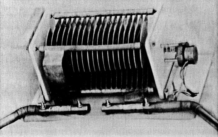
Fig 3 - The W5QJR variable capacitor for loop antennas. Note the mounting details.
I would like to thank Roger Faulstick, KD4AS, for his encouragement and all the work he has done performing experiments and collecting meaningful performance data. I also wish to acknowledge and thank all those who have written to me with encouraging comments.
Notes
- M. K. Patterson, "Down To Earth my Antenna," Electronics, Aug 1967.
- L. McCoy, "The Army Loop in Ham Communications," QST, Mar 1968, pp 17-18.
- G. Hall and B. Schetgen, Six Winners Emerge from the ARRL Antenna Competition," QST, Feb 1985, pp 44-47.
- This capacitor is available from W5OJR Antenna Products, PO Box 334, Melbourne FL 32902. Send a business-size SASE for further information.
W5QJR, Ted Hart.