Electromagnetic pulse and the radio amateur 4
What can be done to protect an Amateur Radio station from lightning and EMP transients? Here are some ideas on procedures and protective devices.
The equipment test program described in the preceding three articles demonstrates that most Amateur Radio installations can be protected from lightning and EMP transients with a basic protection scheme. Most of the equipment is not susceptible to damage when all external cabling is removed. You can duplicate this stand-alone configuration simply by unplugging the ac power cord from the outlet, disconnecting the antenna feed line at the rear of the radio and isolating the radio gear from any other long metal conductors. Or, you can add two transient-protection devices to the interconnected system; that will also closely duplicate the stand-alone configuration.
The ac power line and antenna feed line are the two important points that should be outfitted with transient protection. This is the minimum basic protection scheme recommended for all Amateur Radio installations. (For fixed installations, consideration should also be given to the antenna rotator connections - see Fig 12.) Hand-held radios equipped with a "rubber duck" require no protection at the antenna jack. If a larger antenna is used with the hand-held transceiver, however, a protection device should be installed.
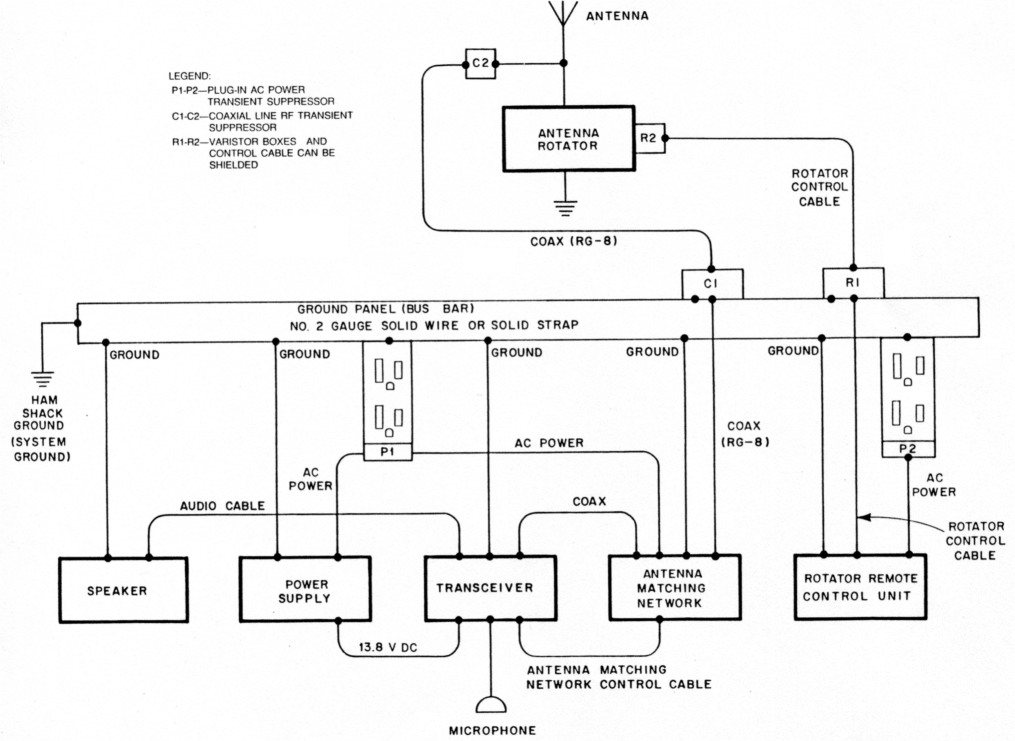
Fig 12 - Transient suppression techniques applied to an Amateur Radio station.
General considerations
Because of the unpredictable energy content of a nearby lightning strike or other large transient, it is possible for a metal-oxide varistor (MOV) to be subjected to an energy surge in excess of its rated capabilities. This may result in the destruction of the MOV and explosive rupture of the package. These fragments can cause damage to nearby components or operators and possibly ignite flammable material. Therefore, the MOV should be physically shielded.
A proper ground system is a key factor in achieving protection from lightning and EMP transients. A low-impedance ground system should be installed to eliminate transient paths through radio equipment and to provide a good physical ground for the transient-suppression devices. A single-point ground system is recommended (see Fig 13). Inside the station, single-point grounding can be had by installing a ground panel or bus bar. All external conductors going to the radio equipment should enter and exit the station through this panel. Install all transient-suppression devices directly on the panel. Use the shortest length(s) possible of no. 6 solid wire to connect the radio equipment case(s) to the ground bus.
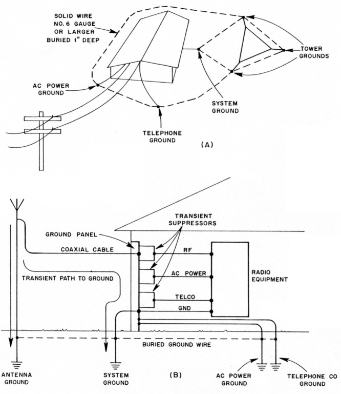
Fig 13 - At A, the proper method of tying all ground points together. The transient path to ground with a single-point ground system and use of transient suppressors is shown at B.
Fixed installations
AC power-line protection
Tests have indicated that household electrical wiring limits the maximum transient current that it will pass to approximately 120 A. Therefore, the amateur's station should, if possible, be installed away from the house ac entrance panel and breaker box to take advantage of these limiting effects.
Ac power-line protection can be provided with easy-to-install, plug-in transient protectors. Ten such devices were tested (see Table 9). Six of these can be plugged directly into an ac outlet. Four are modular devices that require more extensive installation and, in some cases, more than one module.
| Manufacturer | Device | Approximate cost (US $) | Measured high-Z clamping voltage (V) |
|---|---|---|---|
| Modules | |||
| Fischer | FCC-120E-P | 55 | 420 |
| Joslyn | 1250-32 | 31 | 940 |
| General Semiconductor | 587B051 | 56 | 600 |
| General Semiconductor | PHP 120 | 50 | 400 |
| Plug-ins | |||
| Joslyn | 1270-02 | 49 | 600 |
| Til | 428 | 45 | 410 |
| Electronic Protection Devices | Lemon | 45 | 580 |
| Electronic Protection Devices | Peach | 60 | 1000 |
| S L Weber | LG-10 | 13 | 600 |
| Archer | 61-2785 | 22 | 300 |
The plug-in-strip units are the best overall choice for the typical amateur installation. They provide the protection needed, they're simple to install and can be moved easily with the equipment to other operating locations. The modular devices are second choices because they all require some installation, and none of the units tested provided full EMP protection for all three wires of the ac power system.
We consider the Til model 428 Plug-In Powerline Protector to be the best overall protector. It provides transient paths to ground from the hot and neutral lines (common mode) as well as a transient path between the hot and neutral lines (normal mode). The model 428 uses three MOVs and a 3-electrode gas-tube arrestor to provide fast operation and large power-dissipation capabilities. This unit was tested repeatedly and operated without failure.
Several other plug-in transient protectors provide 3-wire protection, but all operate at higher clamping voltages. Other low-cost plug-in devices either lack the 3-wire protection capability or have substantially higher clamping voltages. Some of these are the:
- Joslyn 1270-02. It provides full 3-wire (common and normal mode) transient-path protection, but at a slightly higher cost and at a higher clamping voltage.
- Lemon and Peach protection devices manufactured by Electronic Protection Devices, Inc. The Lemon provides full (command and normal mode) 3-wire protection, but at a higher clamping voltage; the Peach has a dangerously high (1000 V) clamping voltage.
- Archer (Radio Shack) 61-2785 [Replaced by a new model. - Ed.]. This unit provides excellent clamping performance at low cost, but it offers normal-mode protection only (a transient path between the hot and neutral leads). It will provide some protection for lightning transients, but not enough for EMP.
- S. L. Waber LG-10. The lowest-cost device does not provide full three-wire protection (normal mode only) and has a clamping voltage of 600. This unit can provide limited transient protection for lightning, but not the 3-wire protection recommended for EMP transients.
The transient suppressors require a 3-wire outlet; the outlet should be tested to ensure all wires are properly connected. In older houses, an ac ground may have to be installed by a qualified electrician. The ac ground must be available for the plug-in transient suppressor to function properly. The ac ground of the receptacle should be attached to the station ground bus, and the plug-in receptacle should be installed on the ground panel behind the radio equipment.
Emergency power generators
Emergency power generators provide two major transient-protection advantages. First, the station is disconnected from the commercial ac power system. This isolates the radio equipment from a major source of damaging transients. Second, tests have shown that the emergency power generator may not be susceptible to EMP transients.
When the radio equipment is plugged directly into the generator's outlets, transient protection may not be needed. If an extension cord or household wiring is used, transient protection should be employed.
An emergency power generator should be wired into the household circuit only by a qualified electrician. When so connected, a switch is used to disconnect the commercial ac power source from the house lines before the generator is connected to them. This keeps the generator output from feeding back into the commercial power system. If this is not done, death or injury to unsuspecting linemen can result.
Feed-line protection
Coaxial cable is recommended for use as the transmission line because it provides a certain amount of transient surge protection for the attached equipment. The outer conductor shields the center conductor from the transient field. Also, the cable limits the maximum conducted transient voltage on the center by arcing the differential voltage from the center conductor to the grounded cable shield.
By providing a path to ground ahead of the radio equipment, the gear can be protected from the large currents impressed upon the antenna system by lightning and EMP. A single protection device installed at the radio's antenna port will protect the radio, but not the transmission line. To protect the transmission line, another transient protector must be installed between the antenna and the transmission line (see Fig 12).
RF transient-protection devices from three manufacturers were tested (see Table 10) using RG-8 cable equipped with UHF connectors. All of the devices shown can be installed in a coaxial transmission line. Recall that during the tests the RG-8 cable acted like a suppressor; damaging EMP energy arced from the center conductor to the cable shield when the voltage level approached 5.5 kV.
| Manufacturer | Device | Approximate cost (US $) | Measured high-Z clamping voltage (V) |
|---|---|---|---|
| Fischer | FCC-250-300-UHF | 55 | 393 |
| Fischer | FCC-250-350-UHF | 55 | 260 |
| Fischer | FCC-250-150-UHF | 55 | 220 |
| Fischer | FCC-250-120-UHF | 55 | 240 |
| Fischer | FCC-450-120-UHF | 55 | 120 |
| Polyphaser | IS-NEMP | 83 | 140 |
| Polyphaser | IS-NEMP-1 | 83 | 150 |
| Polyphaser | IS-NEMP-2 | 83 | 160 |
| Alpha Delta | LT | 20 | 700* |
| Alpha Delta | R-T | 30 | 720* |
| Note: The transmitter output power, frequency of operation and transmission line SWR must be considered when selecting any of these devices. | |||
| * The newer Alpha Delta LT and R-T "EMP" models have clamping voltages one-third of those shown here. | |||
Low price and a low clamping-voltage rating have to be considered in the selection of an RF transient-protection device. However, the lower-cost devices have the higher clamping voltages, and the higher-cost devices have the lower clamping voltages. Because of this, we selected medium-priced devices manufactured by Fischer Custom Communications. The Fischer Spikeguard Suppressors (about $55) for coaxial lines can be made to order to operate at a specific clamping voltage. The Fischer devices satisfactorily suppressed the damaging transient pulses, passed the transmitter RF output power without interfering with the signal and operated effectively over a wide frequency range.
Polyphaser Corporation devices are also effective in providing the necessary transient protection. However, the available devices limited the transmitter RF output power to 100W or less. These units cost approximately $83 each.
The Alpha Delta Transi-Traps tested were low-cost items, but not suitable for EMP suppression because of their high (over 700-V) clamping levels. [New Alpha Delta "EMP" units have clamping voltages about one-third that of the older units tested here. - Ed.]
RF coaxial protectors should be mounted on the station ground bus bar. If the Fischer device is used, it should be attached to a grounded UHF receptacle that will serve as a hold-down bracket. This creates a conductive path between the outer shield of the protector and the bus bar. The Polyphaser device can be mounted directly to the bus bar with the bracket provided.
Attach the transceiver or antenna matching network to the grounded protector with a short (6 foot or less) piece of coaxial cable. Although the cable provides a ground path to the bus bar from the radio equipment, it is not a satisfactory transient-protection ground path for the transceiver.
Another ground should be installed between the transceiver case and the ground bus using solid no. 6 wire. The coaxial cable shield should be grounded to the antenna tower leg at the tower base. Each tower leg should have an earth ground connection and be connected to the single-point ground system as shown in Fig 13.
Antenna rotators
Antenna rotators can be protected by plugging the control box into a protected ac power source and adding protection to the control lines to the antenna rotator. When the control lines are in a shielded cable, the shield must be grounded at both ends. MOVs of the proper size should be installed at both ends of the control cable. At the station end, terminate the control cable in a small metal box that is connected to the station ground bus. Attach MOVs from each conductor to ground inside the box. At the antenna end of the control cable, place the MOVs inside the rotator case or in a small metal box that is properly grounded.
For example, the Alliance HD73 antenna rotator uses a 6-conductor unshielded control cable with a maximum control voltage of 24.7. Select an MOV with a clamping voltage level 10% higher (27 V or more) so the MOV won't clamp the control signal to ground.
DC power-supply protection
Mobile installations
The mobile amateur station environment exposes radio equipment to other transient hazards in addition to those of lightning and EMP. Currents as high as 300 A are switched when starting the engine, and this can produce voltage spikes of over 200 V on the vehicle's electrical system. Lightning and EMP are not likely to impact the vehicle's electrical system as much as they would that of a fixed installation because the automobile chassis is not normally grounded. This would not be the case if the vehicle is inadvertently grounded; for example, when the vehicle is parked against a grounded metal conductor. The mobile radio system has two advantages over a fixed installation: Lightning is almost never a problem and the vehicle battery is a natural surge suppressor.
Mobile radio equipment should be installed in a way that takes advantage of the protection provided by the battery (see Fig 14). To do this, connect the radio's positive power lead directly to the positive battery post, not to intermediate points in the electrical system such as the fuse box or the auxiliary contacts on the ignition switch. To prevent equipment damage or fire, should the positive lead short to ground, an in-line fuse should be installed in the positive lead where it is attached to the battery post.
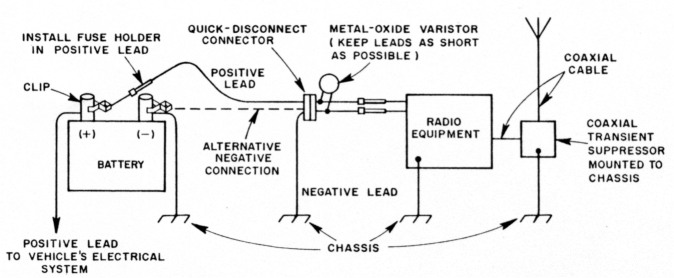
Fig 14 - Recommended method of connecting mobile radio equipment to the vehicle battery and antenna.
Connect the negative power lead to the chassis on the battery side of the quick- disconnect connector. Although it would help prevent alternator whine, connecting the negative power lead directly to the battery post is not recommended from an EMP standpoint.
An MOV should be installed between the two leads of the equipment power cord. A GE MOV (V36ZA80) is recommended for this application. This MOV provides the lowest measured clamping voltage (170 V) and is low in cost.
Mobile antenna installation
Although tests indicate that the mobile radios can survive an EMP transient without protection for the antenna system, protection from lightning transients is still required. A coaxial-line transient suppressor should be installed on the vehicle chassis between the antenna and the radio's antenna connector. A Fischer suppressor can be attached to a UHF receptacle that is mounted on, and grounded to, the vehicle chassis. The Polyphaser protector can be mounted on, and grounded to, the vehicle chassis with its flange. Use a short length of coaxial cable between the radio and the transient suppressor.
Clamping voltage calculation
When selecting any EMP-protection device to be used at the antenna port of a radio, several items must be considered. These include: transmitter RF power output, the SWR and the operating frequency. The protection device must allow the outgoing RF signal to pass without clamping. A clamping voltage calculation must be made for each amateur installation.
The RF-power input to a transmission line develops a corresponding voltage that becomes important when a voltage-surge arrestor is in the line. SWR is important because of its influence on the voltage level. The maximum voltage developed for a given power input is determined by:
![]()
where:
P = peak power in W
Z = impedance of the coaxial cable (ohms)
V = peak voltage across the cable
This equation should be used to determine the peak voltage present across the transmission line. Because the RF transient-protection devices use gas-discharge tubes, the voltage level at which they clamp is not fixed; a safety margin must be added to the calculated peak voltage. This is done by multiplying the calculated value by a factor of three. This added safety margin is required to ensure that the transmitter's RF output power will pass through the transient suppressor without causing the device to clamp the RF signal to ground. The final clamping voltage obtained is then high enough to allow normal operation of the transmitter while providing the lowest practical clamping voltage for the suppression device. This ensures the maximum possible protection for the radio system.
Here's how to determine the clamping voltage required. Let's assume the SWR is 1.5:1. The power output of the transceiver is 100 W PEP. RG/8 coaxial cable has an impedance of 52 ohms. Therefore
P = 100 W
Z = 52 ohms
SWR = 1.5
Substituting these values in Eq 3:
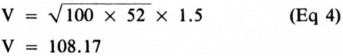
Note that the voltage, V, is a peak value since the power was measured in peak watts. The final clamping voltage (FCV) is three times this value or 324.45 V. Therefore, a coaxial-line transient suppressor that clamps at or above 324 V should be used.
The cost of a two-point basic protection scheme is estimated to be $100 for each fixed amateur station. This includes the cost of one Til model 428 plug-in power-line protector ($45) and one Fischer coaxial-line protector ($55).
Inexpensive transient-protection devices
Here are two low-cost protection devices you can assemble. They performed flawlessly in the tests.
SIOV AC box
The SIOV (Siemens metal-Oxide Varistor) power-line protection device shown in Fig 15 is fabricated by installing a duplex receptacle in a metal electrical box. Power is brought into the box through a 6-foot-long, 3-conductor power cord. A fuse is installed in the incoming hot wire to guard against harmful effects if one of the protective devices shorts. MOVs (Siemens S 14K 130) are installed - with the shortest possible lead lengths - between the hot and neutral, hot and ground and neutral and ground leads. The estimated cost of this unit is $11.
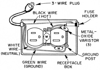
Fig 15 - Pictorial diagram of an inexpensive, homemade ac power-line transient protector. This approach may be applied to multiple outlets; see text.
UHF coaxial T
The radio antenna connection can be protected by means of another simple device. As shown in Fig 16, two spark gaps (Siemens BI-A350) are installed in series at one end of a coaxial cable T connector. Use the shortest practical lead length (about '/e in) between the two spark gaps. One lead is bent forward and forced between the split sections of the inner coaxial connector until the spark gaps approach the body of the connector. A short length of insulating material (we used Mylar® ) is placed between the spark gaps and the connector shell. The other spark-gap lead is folded over the insulator, then conductive (metallic) tape is wrapped around the assembly. This construction method proved durable enough to allow many insertions and removals of the device during testing. Estimated cost of this assembly is $9. Similar devices can be built using components from Joslyn, General Electric, General Semiconductor or Siemens.
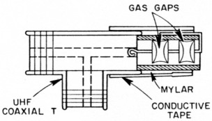
Fig 16 - Pictorial diagram of an inexpensive, homemade transmission-line transient protector. See text for description of assembly.
Summary
Amateurs should be aware of which components in their radio system are most likely to be damaged by EMP. They should also know how to repair the damaged equipment. Amateurs should know how to reestablish communications after an EMP event, taking into consideration its adverse effects on the earth's atmosphere and radio equipment. One of the first things that would be noticed, providing the radio equipment is operative, is a sudden silence in radio transmissions across all frequencies below approximately 100 MHz. This silence would be due in part to the damage by the EMP transient to unprotected radio gear. Transmissions from one direction, the direction of the nuclear blast, would be completely out. RF signal loss by absorption and attenuation by the nuclear fireball are the reasons for this.
After an EMP event, the amateur should be prepared to operate CW. CW gives the most signal power under adverse conditions. It also provides a degree of message security from the general public.
Amateurs should develop the capability and flexibility to operate in more than one frequency band. The lower ground-wave frequencies should be useful for long-distance communications immediately after an EMP event. Line-of-sight (LOS) VHF would be of value for local communications purposes.
What can be done to increase the survivability of an Amateur Radio station? Here are some suggestions:
- If you have spare equipment, keep it disconnected; use only the primary station gear. The spare equipment would then be available after an EMP event.
- Keep equipment turned off and antenna and power lines disconnected when the equipment is not in use.
- Connect only those external conductors necessary for the current mode of operation.
- Tie all fixed equipment to a single-point earth ground to prevent closed loops through the ground.
- Obtain schematic diagrams of your equipment and tools for repair of the equipment.
- Have spare parts on hand for sensitive components of the radio equipment and antenna system.
- Learn how to repair or replace the sensitive components of the radio equipment.
- Use nonmetallic guy lines and antenna structural parts where possible.
- Obtain an emergency power source and operate from it during periods of increased world political tension. The power source should be completely isolated from the commercial power lines.
- Equipment power cords should be disconnected when the gear is idle. Or, the circuit breaker for the line feeding the equipment should be kept in the OFF position when the station is off the air.
- Disconnect the antenna lead-in when the station is off the air. Or, use a grounding antenna switch and keep it in the GROUND position when the equipment is not in use.
- Have a spare antenna and transmission line on hand to replace a damaged antenna system.
- Install EMP surge arrestors and filters on all primary conductors attached to the equipment and antenna.
- Retain tube type equipment and spare components; keep them in good working order.
- Do not rely on a microprocessor to control the station after an EMP event. Be able to operate without microprocessor control.
Conclusion
The recommendations contained in this report were developed with low cost in mind; they are not intended to cover all possible combinations of equipment and installation methods found in the amateur community. Amateurs should examine their own requirements and use this report as a guideline in providing protection for the equipment.
Part 1 - Part 2 - Part 3 - Part 4
W4PWF, Dennis Bodson.