Professional quality DTMF decoder and selcall system
This inexpensive, simple-to-build project monitors the repeater for you! Don't be bothered with idle chatter, Or miss a friend's call.
My radio club was looking for a useful 2-meter repeater project when the idea of creating a selective calling (SELCALL) system surfaced. Club members searched through The ARRL Handbook for ideas, but were surprised to see only phase-locked-loop (567) technology.
The 567 device, like most tone decoders, is prone to false decodes from harmonics of the desired tones. Many commercial designs use substantial audio filtering to separate the inputs into a low and a high group to minimize the harmonics "seen" by the decoders. Commercially manufactured filters are expensive. The homemade approach is less costly; however, expensive test equipment would be necessary to set and maintain these filters. And, an accurate frequency counter is required to set the 567s. Lastly, the 567 decoders disregard Bell specifications (timing, differential amplitude, and so on) that were designed to ensure reliable operation while minimizing false decodes caused by voice phonemes and noise bursts that momentarily meet the frequency constraints of the dual-tone, multi-frequency (DTMF) system.
More advanced decoders have long since replaced old LC and 567 decoders. For about $70, you can build a SELCALL unit that responds to both an individual and a group call code and provides a means of controlling external equipment with DTMF tones. Best of all, no exotic test equipment is necessary to align the completed unit.
The Circuit
The design presented in Fig 1 is based on a family of ICs made by Silicon Systems, Inc: SSI-202P, 203P and 204P. Each decoder IC uses switched-capacitor technology to yield both high- and low-group tone filters, as well as the decoding function. Filter tuning is derived from a clock controlled by an inexpensive 3.579-MHz crystal. Thus, test equipment is unnecessary for alignment of the decoder. Because the decoder's switched- capacitor filters do not suffer the tuning drift problems of RC filters common in PLL decoders, this SELCALL is well-suited to a mobile environment.
The design calls for 12 CMOS ICs, one relay, and a handful of discrete components. The circuit can be built on a single PC board, and housed in your rig's external speaker enclosure.' A ribbon cable connects the main board to the accessory board(s).
A 16-pin header is used for the accessory socket, and is included on the unit. For several dollars more, other projects or planned additions to the circuit can be made. These projects may include an LED display, or a memory unit that allows others to access your SELCALL and leave their SELCALL code (or phone number).
Operation
The SELCALL connects to a transceiver through the radio's earphone jack. The only other connection is to a power source-9 to 15 V (ac or dc).
In normal SELCALL operation, received audio is blocked from the speaker until a valid DTMF sequence is received. This feature enables you to monitor a frequency without listening to every conversation. The SELCALL does the "listening," and "announces" when someone has called.
On receipt of a valid code sequence, the unit enables the speaker and optional audible alerting device, such as a buzzer. If you wish to listen to the activity on the channel, throw the SELCALL's switch to MANUAL for normal operation. If you are not monitoring the frequency, LEDs latch ON to indicate that your SELCALL sequence was received.
What constitutes a valid code sequence? The unit features immunity to false decoding caused by partial decodes and repeated digits. It looks for the assigned digits, as well as a digit's proper placement within the string of digits. If your SEL-CALL is programmed for the code 000, it will not respond to anything other than 0-0-0. Pressing the 0 key continuously over a period of time will not be mistaken for a valid code sequence. If the code sequence is 19*, only that exact sequence works.
The unit has two separate SELCALL circuits. One is used for an individual call, the other for a group call. Both circuits can be programmed to accept any three-digit DTMF sequence from a 16-digit keypad (0-9, A-D, # and *).
A fourth DTMF digit accesses three additional functions. Two are latching functions with LED indicators. The third is momentary, and functions as a remote reset: It disables the speaker, and turns off latched functions. The intent of these secondary functions is more than turning on LEDs. By adding transistors and relays to the circuit, control of peripheral equipment is possible (turning on the coffee pot or opening the garage door, for example). The circuit can drive 5-V relay solenoids directly, allowing for control of peripheral equipment.
Programming
The SELCALL unit is easy to program. U3 in Fig 1 provides decoded tone outputs. The inputs to the logic decoders are labeled 11, 12 and 13 (one for each digit of. the "individual" SELCALL circuit), and G1, G2 and G3 (one for each digit of the "group" SELCALL circuit). Strap the pin corresponding to the desired decoded digit to the appropriate input pin. For example, for an individual code of 730, run jumpers from U3's "7" output to 11, "3" to 12 and "0" to 13. Let's say the group call code is 55*. Run jumpers from the "5" ouput to 01, "5" to G2 and "*" to G3. For special functions, strap the appropriate output from U3's output to select the DTMF digits that will control special functions Fl, F2 and F3. For a custom peripheral interface, connect your interface circuit to OPT F1 or OPT F2.
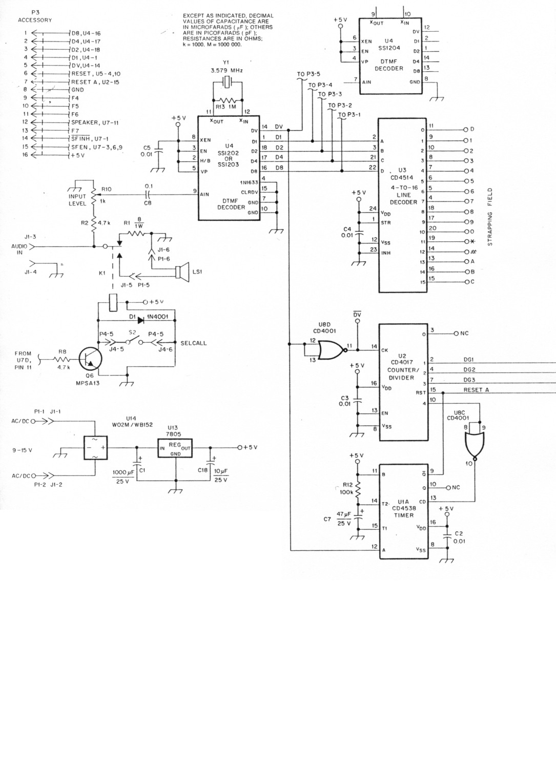
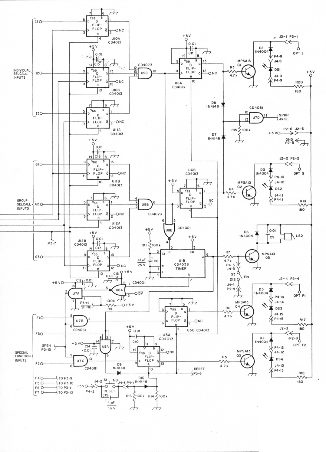
Fig 1 - All resistors are carbon composition, 1/4 W, 10% tolerance unless otherwise noted. Components used in this project are available from A & A Engineering, 2521 W LaPalma, Unit K, Anaheim, CA 92801, tel 714-952-2114, Radio Shack, or Jameco Electronics, 1355 Shoreway Rd, Belmont, CA 94002, tel 415-592-8097. SSI DTMF decoder chips may also be purchased from Hall-Mark Electronics, Inc, 11333 Pagemill, Dallas, TX 75243. tel 214-343-5000.
| C1 | 1000 µF, 25 V electrolytic. |
| C2-5,9-17 | 0.01 µF, disc ceramic. |
| C6,7 | 47 µF, radial. |
| C8 | 0.1 µF disc ceramic. |
| C18 | 10 µF, 25 V electrolytic. |
| C19 | 1 µF, 16 V electrolytic. |
| D1-6 | 1N4004 |
| D7-10 | 1N4148 |
| DS1-DS4 | LEDs. |
| J1,2 | 6 pin singular 0.156 header. |
| J3 | 16 pin dual 0.100 header. |
| J4 | 15 pin singular 0.100 header. |
| K1 | 5 V SPST DIP relay. |
| LS1 | 8 Ω speaker |
| LS2 | Piezo alarm. |
| Q1-Q6 | MPSA13 Darlington transistor. |
| R1 | 8.2 Ω |
| R2-8 | 4.7 MΩ |
| R9,11,12,14-16 | 100 kΩ |
| R10 | 1 kΩ |
| R13 | 1 MΩ |
| R17-20 | 180 Ω |
| S1 | Push-button, normally open switch. |
| S2,S3 | SPST toggle switches. |
| U1 | CD4538, dual-monostable multivibrator. |
| U2 | CD4017, decade counter/divider with 10 decoded outputs. |
| U3 | CD4514 analog multiplexer/ demultiplexer. |
| U4 | SSI 202P DTMF decoder (RS 276-1303). |
| U5,6,10-12 | CD4013, dual D flip-flop. |
| U7 | CD4081, quad 2 input AND buffered B series gate. |
| U8 | CD4001, quad 1 input NOR buffered B series gate. |
| U9 | CD4073, double buffered, triple 3 input AND gate. |
| U13 | 7805 voltage regulator. |
| U14 | WO2M/WB152 fullwave bridge. |
| Y1 | 3.579 MHz crystal. |
Circuit Operation
Audio from the radio's earphone jack is fed into the circuit's AUDIO IN jack, J1. This audio is routed through an 8 Ω resistor to ground (the resistor acts as a load for the receiver; very little audio power is required by the SELCALL system). A small sample of the signal is fed into U4, the tone decoder. DTMF signals are decoded, and the tone information (in binary format) is fed to a 4-to-16 line decoder, U3. U4 also sources a strobe pulse called DV (data valid). The DV strobe clocks U2, a digit counter, and triggers U1A, a timer. The timer automatically resets all decoding circuits five seconds after loss of tone at J1. This protects against "partial decode" falling for situations in which the last digits of someone else's code are identical to the first digits of your code. This timer is retriggerable.
If the time from the start of one tone to the start of the next is five seconds or less, the timer will not reset. This provides sufficient time for even the slowest button-pusher to enter the right sequence.
U2 is the digit counter and clocks latches U10, U11 and U12. If the correct data from U3 is present at these latches when the appropriate clock occurs, AND gates U9A and U9B toggle and signal a valid code sequence.
U2 also resets upon receipt of a fourth tone. This prevents someone from repeatedly pressing buttons in an attempt to discover the correct code by trial and error.
When the condition for a valid code sequence is met at either AND gate (U9A or U9B), a latch is set (U6A for an individual code, U6B for a group code). These latches turn on a corresponding LED (DS1-DS2) and relay driver (Q2, Q3). They also turn on Q1, driving K1A and connecting a speaker, LS1, to the radio.
The AND gates (U9A and U9B) trigger another timer (U1A), turning on the buzzer (if enabled) and allowing reception of the fourth special tone. This timer allows the SELCALL unit to listen for approximately five seconds. If you want to turn on a special function, you must do it within five seconds of the successful recognition of your code by the SELCALL unit.
Once enabled, the buzzer sounds for five seconds. If the radio is unattended, the LEDs are latched to indicate a call was received. The radio speaker's audio remains on until the SELCALL system is reset. This may be done by pressing the RESET push button, or by sending an F3 tone immediately after another valid code sequence. This allows the calling party to turn off your speaker if you do not respond.
Conclusion
Although the SSI DTMF decoder chips have a wide dynamic range, they can be overloaded. Set RIO for 600 mV of signal at the IC for safe operation. Use 0.01-µF decoupling capacitors when working in an RF environment. It is worth the extra expense.
Fig 2 shows the completed circuit. Parts can be obtained from the junk box, local hamfest or A & A Engineering. Use IC sockets and be sure the relay has a 5-V coil. The transistors should be MPSA13s; the high gain and current capabilities of this Darlington are needed.
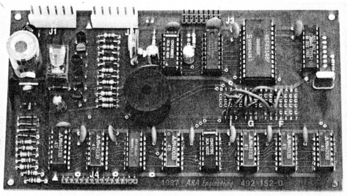
Fig 2 - The DTMF decoder and SELCALL circuit. The unit shown was built from an A & A Engineering PC board and parts kit. (See text.)
Comments, critiques and suggestions for added features are welcome. To packet a message to me use AA4MY @ WA4LPD. Happy SELCALLing!
AA4MY, Vince Yakamavich.