Phase noise and its effects on amateur communications 1
A mystery to many amateurs, phase noise is nonetheless an important performance parameter of our gear. This month, we look into its causes and effects.
It's a Saturday evening and you're listening on 80 meters, tuning for a response to your just-completed CQ. You hear a weak station calling, and just as you are about to copy the last part of the call sign, the signal is masked by a loud, raspy CQ. The station answering you is totally masked by this hissy signal. This noise is clobbering the whole band! You recognize the call sign of the interfering station-it's George, the new Novice just a few blocks away. After you tune up the band to confirm that he is really operating in the Novice subband, you're tempted to give him a call and tell him what a lousy radio he purchased, but good sense and curiosity prompt you to try to figure out the cause of the interference.
You doubt your receiver is the problem, because it has excellent dynamic range, and turning on its RF attenuator doesn't eliminate that awful rasping. Therefore, it must be George's transmitter. Maybe his transmitter has a parasitic oscillation, but you've never heard a signal so thoroughly wipe out an entire band.
Most likely, the cause of this problem is oscillator phase noise. What causes it? In this example, it could be George's transmitter, but it could also be your receiver. Oscillator phase noise can dramatically impair your ability to communicate with other stations, whether it comes from the receiver, the transmitter, or both.
What is Oscillator Phase Noise?
Oscillators have formed the basis of most radio communications systems since spark-gap transmitters were retired. Originally, these oscillators used piezoelectric crystals or high-Q LC tuned circuits as resonant elements. More recently, phase-locked loops (PLLs) have been used in radios with synthesized local oscillators. There is no theoretical reason that prevents a phase-locked oscillator from having better phase-noise characteristics than a free-running oscillator using an LC tuned circuit.
An ideal oscillator would generate a sine wave at a given frequency with no deviation in amplitude or phase over time. If we looked at this signal with an ideal spectrum analyzer, we would see all of the energy concentrated at the fundamental frequency and none at any other frequency. If ideal oscillators existed, problems with phase noise wouldn't exist.
Oscillator signals vary in both amplitude and phase as a function of time. These variations are referred to as amplitude noise and phase noise. Amplitude noise is an undesired variation in the amplitude of an oscillator signal. If we use an oscilloscope to look at oscillator output, we can see that the amplitude peaks of the sine wave vary with time (Fig 1).
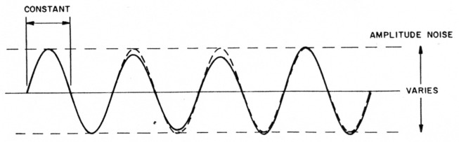
Fig 1 - Oscillator amplitude noise effects as viewed on an oscilloscope. The broken line shows the output of an ideal oscillator; the solid line shows the output waveform of an oscillator with a large amount of amplitude noise.
Phase noise is an undesired variation in the phase of the signal. In this case, an oscilloscope shows that the time between zero crossings of the signal varies over time when compared to the zero crossings of an ideal sine wave. An exaggerated example of phase noise is shown in Fig 2.
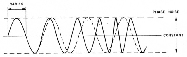
Fig 2 - Oscillator phase-noise effects as viewed on an oscilloscope. The broken line shows the output of an ideal oscillator; the solid line shows the output waveform of an oscillator with a large amount of phase noise.
Several factors combine to make amplitude noise much less important than phase noise. The first is that most oscillators tend to produce less amplitude noise than phase noise. This occurs because the active devices in most oscillators are operated in a gain-saturated condition. Gain saturation occurs when increasing the input to a device or stage results in no further increase in output. If a device or stage is sufficiently gain saturated, small changes in the amplitude of the input signal (amplitude noise, in other words) produce no change in the output level.
Amplitude noise is secondary in importance to phase noise for another reason. Most modern ham rigs use mixers in their signal-generation schemes. Because mixers are usually operated with their local-oscillator input ports gain saturated, any amplitude noise on the input signal generally does not appear on the mixer output.
Specifying Phase Noise Levels
There are many ways to display oscillator phase noise. The most common presentation is called single-sideband (SSB) phase noise. This is simply a display of the phase-noise characteristics on one side of the carrier. The SSB phase-noise presentation has probably achieved its widespread use because SSB phase noise is easy to measure and interpret for the average person who is familiar with RF measurement techniques. The display of SSB phase noise is exactly what you would see if the oscillator was observed using an ideal spectrum analyzer with a 1-Hz sampling bandwidth.
The vertical axis is the SSB phase noise measured in units of "dBc/Hz." The "dBc" means that we are measuring the power in the phase noise relative to the power in the carrier. The "Hz" implies that we are making this measurement in a 1-Hz bandwidth. (Phase noise is usually not actually measured in a 1-Hz bandwidth, for reasons of instrumentation limitations. See the sidebar entitled "A Sample Phase-Noise Scenario.")
A Sample Phase-Noise Scenario
Phase-noise levels are specified in decibels relative to the carrier level, at a particular offset frequency in a 1-Hz bandwidth, or dBc/Hz. But this doesn't tell us how much interference is caused by a particular phase-noise level at a given offset frequency, because we don't use 1-Hz receiving bandwidths. If you know your receiver's IF bandwidth, the received carrier power of the phase-noisy signal, the phase-noise level and the frequency offset, you can easily calculate the received power of the phase noise. Then you can calculate how strong a desired signal must be to be copiabie through the phase-noise interference.
Let's assume that somehow we know the phase noise on a transmitted signal is -110 dBc/Hz at 4 kHz (where our receiver is tuned) from the carrier. Let's also assume that our receiving bandwidth is 500. This means that there is 500 times as much phase-noise power getting through our receiver as there would be at a receiving bandwidth of 1 Hz. A power ratio of 500, expressed In dB, Is 27. Because our receiver bandwidth is wider than 1 Hz, the phase-noise hiss we hear is not 110 dB below the carrier: it's 27 dB greater in our 500-Hz bandwidth. That's -83 dBc/ 500 Hz.
If the carrier of the phase-noisy signal produces 5000 microvolts at the receiver antenna terminals, the phase noise in our 500-Hz receiving bandwidth is 83 dB below 5000 microvolts.t This is equivalent to 0.35 microvolt at the receiver's antenna terminals.
This is more than enough signal strength to degrade the sensitivity of a good HF receiver. In fact, a desired signal of reasonable strength could easily be masked by this much phase noise. The sensitivity of a typical receiver is about -137 dBm for a 500-Hz receiving bandwidth. Such a receiver can detect a signal as weak as 0.03 microvolt. In our sample case, the phase noise hits 0.35 microvolt at the receiver input-21 dB greater than the weakest signal our receiver can hear. The phase-noisy incoming signal has degraded our receiver's sensitivity by 21 dB!
David Newkirk, AK7M, Assistant Technical Editor, ()ST
- How true to life Is the strength of the interfering signal In this example? On a receiver S meter calibrated for S9 = 50 µV (a common standard), 5000 µV is 40 dB over S9, assuming that the meter calibration is accurate. Signals of this strength are commonplace at many locations.
The horizontal axis represents the A Sample Phase-Noise Scenario difference between the measurement and oscillator frequencies, and is usually referred to as the offset frequency. Offset frequency is measured in Hz, and it is usually plotted on a logarithmic scale. An offset of 1 kHz means that we are measuring the phase noise 1 kHz from the carrier; an offset of 10 kHz is 10 kHz from the carrier, and so on. A 10-kHz offset from a 10-MHz carrier means that we are making measurements at 9.99 MHz or 10.01 MHz.
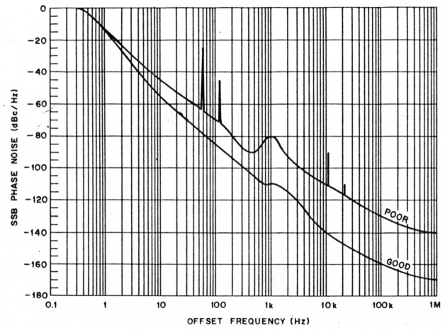
Fig 3-Phase-noise characteristics of two synthesized oscillators. The lower curve represents the output of a well-designed synthesized oscillator. The upper curve represents that of a poorly designed synthesized oscillator. Note the broad peak at 1 kHz, and the spikes visible near 60 and 120 Hz, and 11 and 22 kHz. (See text.)
Glossary of Terms
Amplitude noise - Undesired variations in the amplitude of an oscillator or synthesizer signal.
Blocking - The region in which a receiver limits the output resulting from a desired signal because of an undesired signal on a different frequency.
Gain saturation - The point at which an increase in input to a device or circuit results in no increase in output.
Natural frequency - The frequency in a feedback circuit (such as a PLL) that produces optimum loop response.
Offset - The difference in frequency between the carrier and the center of the sampling bandwidth in a phase-noise measurement system.
Phase Noise - Undesired variations in the phase of an oscillator signal.
Underdamping - Lack of sufficient negative feedback in a loop (such as a PLL). The loop tends to oscillate in this state.
Two typical phase-noise measurements are shown in Fig 3. At an offset frequency of 0 Hz, the SSB phase noise is always 0 dBc/Hz, because we are measuring the carrier power, which is the reference for these measurements. At any other offset, the SSB phase noise is always a negative dB value.
Phase noise in a communications system can be divided into two different regions. The in-band or close-in phase noise is the component that is within the modulation bandwidth of the signal. The out-of-band or far-out phase noise is the component that is beyond the modulation bandwidth of the signal. The modulation bandwidth of an amateur SSB signal is 3 kHz. Therefore, we can define the close-in phase noise of an SSB signal as the noise at offsets of less than 3 kHz, and the far-out phase noise as the phase noise at offsets greater than that. The difference between close-in and far-out phase noise is similarly defined for modes with different modulation bandwidths.
The example used in Fig 3 shows the phase noise for two different synthesized oscillators. The phase-noise plot labeled "good" is the phase noise from an excellent synthesized local oscillator. These phase-noise characteristics are considered "state of the art" for oscillators used in HF receivers. The phase noise from this oscillator rapidly decreases with increasing offset frequency, reaching - 160 dBc/Hz at an offset frequency of 100 kHz. The slight flattening of the phase-noise plot near 1 kHz results from the natural frequency of the PLL. (See the glossary.) (It is normal for a synthesised oscillator to show flattening or a few dB of peaking of the phase noise at the natural frequency of the PLL.) This oscillator would present only minor phase-noise problems in amateur applications.
The phase-noise plot labeled "poor" is typical of what one would expect from an inferior synthesized oscillator. The characteristics of such an oscillator include strong spurious signals, an underdamped PLL, and a high phase-noise floor. (See the glossary.) Large spurious signals are shown at harmonics of 60 Hz and 11 kHz. These signals result from frequency modulation of the oscillator in the PLL, and are generally caused by inadequate shielding or poor loop design. The broad peak at 1 kHz results from an underdamped PLL. Any peaking greater than this is indicative of a poorly designed- phase-locked oscillator.
The phase noise of the poorer oscillator in Fig 3 is only -130 dBc/Hz at a 100-kHz offset. This is generally caused by deficient design of the phase-locked oscillator. Any of the above forms of degradation in the phase noise of an oscillator compromise the performance of a transmitter (and/or receiver).
Effects of Oscillator Phase Noise
In order to understand the effects of phase noise, we have to keep some basic principles in mind. The term communications system used throughout this article refers to the receiver, the transmitter to which the receiver is tuned, and other nearby transmitters. The term system is used to convey that phase-noise effects can result from both the receiver and transmitters, not just the affected receiver.
Principle 1: Whenever a carrier is passed through a mixer, the phase noise of the oscillator driving that mixer is added to the carrier. This means that the oscillator SSB phase-noise power at a given offset frequency is added to the phase noise already present on the carrier at the same offset frequency. For instance, suppose we pass an ideal carrier (one with no phase noise) through two mixers, each driven by an oscillator with an SSB phase noise of -130 dBc/Hz at a 10-kHz offset. After passing the carrier through the first mixer, the SSB phase noise on the carrier is -130 dBc/Hz. After passing the carrier through the second mixer, the phase noise,, on the carrier is -127 dBc/Hz. This is the sum of the phase-noise power of the carrier and local oscillators at the 10-kHz offset frequency. (Summing two equal powers is a doubling of either power, or a 3-dB increase. -127 dBc is twice as much power as -130 dBc.) This example illustrates that the oscillator with the worst phase-noise characteristics limits the performance of the system. This principle holds for both transmitters and receivers.
Principle 2: Phase noise on a transmitted signal causes effects identical to phase noise generated in a receiver. (Of course, transmitter-generated phase noise can affect many users of the radio spectrum, while receiver-generated phase noise only affects the person using that receiver!)
Principle 3: Passing an oscillator signal through a filter reduces the phase noise in accordance with the filter bandwidth and attenuation characteristics. For instance, passing a carrier through a filter (centered on the carrier frequency) with a bandwidth of 20 kHz reduces the phase noise for offset frequencies greater than 10 kHz. As a result of this, transmitters and receivers have an apparent phase noise that is usually less than the sum of their local oscillator phase-noise levels. The apparent phase noise is what limits the system performance.
Phase noise on a transmitted signal causes effects identical to phase noise generated in a receiver.
This effect must be applied with a good understanding of exactly what the filtering does. For instance, in receivers, filtering before a mixer determines the apparent phase noise; in transmitters, filtering after a mixer determines apparent phase noise. The improvement in the apparent phase-noise floor achievable with filtering depends on the power level of the signal being filtered. A normal filter at room temperature generates thermal-noise power of about -170 dBm/Hz. A - 10-dBm signal passed through this filter can achieve a noise floor no lower than -160 dBc/Hz.
Close-In versus Far-Out Phase Noise
The close-in and far-out phase-noise components act on a communications systems in different ways. Close-in phase noise limits the performance of the system even when there is plenty of signal present. With an AM or FM signal, the close-in phase noise limits the maximum signal-to-noise ratio (SNR) that can be achieved by the system. With a frequency-shift-keyed or- a phase-shift-keyed signal, the close-in phase noise limits the maximum bit error rate that the system can achieve. Both of these effects can be quantified once the communications system is defined. With an SSB voice signal, the effects are much harder to predict, but excessive phase noise does degrade SSB signal intelligibility to some extent.
Amplifier Noise: The Hiss that Confuses the Phase-Noise Issue
Plus or minus perhaps 100 Hz to 100 kHz from the transmitted carrier of a synthesized, broadbanded rig, phase noise is usually the major hiss producer.(1) Farther out from the carrier, however-half the band away, perhaps-transmitted amplifier noise from the same broad-banded rig may be busting up weak-signal QSOs for hams across town. What's going on? isn't, all transmitted broadband hiss caused by phase noise?
Phase-noisy oscillators usually manifest themselves as broadband hiss when
- Our receiver has a phase-noisy oscillator, and we tune it to a frequency adjacent to a very strong signal emitted by a phase-quiet transmitter; or
- Our receiver has a phase-quiet oscillator, and we tune it to a frequency adjacent to a very strong signal emitted by a phase-noisy transmitter; or
- Our receiver has a phase-noisy oscillator, and we tune it to a frequency adjacent to a very strong signal emitted by a phase-noisy transmitter.
We can infer from these points that if we install phase-quiet oscillators in transmitter and receiver, we ought to be able to tune our receiver to a frequency closely adjacent to a very strong signal from the transmitter without encountering anything like phase-noise hiss. Yet, after an exhaustive phase-noise cleanup at transmitting and receiving sites, we test our communication system only to discover that the transmitter still emits broadband hiss! The culprit is transmitted amplifier noise.
Just about every modern transmitter or transceiver consists of a high-gain, linear amplifier strip that amplifies the low-level output of oscillators, mixers and phase-locked loops to hundreds of watts or a few kilowatts. Because amplifier circuitry is not perfectly quiet, the output of the transmitter contains noise (hiss) in addition to the amplified signal. Transmitted along with the desired signal, this hiss can degrade the noise floor of nearby receivers-just as transmitted phase noise can.
Where does amplifier noise come from? Thermal noise, for one thing. Electronic components operated at temperatures greater than absolute zero generate random electrical noise. This noise is broadband in nature. Greatly amplified in an audio amplifier-or greatly amplified in a radio transmitter, transmitted as broadband radio noise, received and converted to audio-it sounds like hiss. Random variations in electron flow within active amplifier components (transistors and vacuum tubes) are another source of amplifier noise. Transmitted as broadband radio noise, received and converted to audio, it also sounds like hiss.(2)
How strong will transmitted amplifier noise be on the receiving end? As is the case with phase noise, its severity depends on path loss and antenna gain. The nearer the noisy station, the stronger the noise will be-if your receiver doesn't overload first.
How wide will transmitted amplifier noise be? That depends on the characteristics of tuned circuits and other filters in the transmitter's signal path. If the rig needs no retuning for full power output across an entire amateur band, the power bandwidth of its transmitted amplifier noise may be correspondingly wide. By comparison, the strength of transmitted phase noise generally varies greatly within a relatively small band around the carrier, generally decreasing in amplitude with distance from the carrier.(3)
As we become more aware of the importance of phase-quiet oscillator design, we need to keep transmitted amplifier noise in mind as well. In the laboratory, amplifier noise can interfere with phase-noise measurements, just as a preamplifier can modify the results of receiver measurements. In practice, one ham's transmitted amplifier noise can raise the noise floor for ham neighbors even if all the rigs in the neighborhood have phase-quiet oscillators. Because of this, knocking phase noise back to the Vacuum-tube Age won't be the end of the transmitted-hiss battle. We need quieter broadband transmitter amplifiers, too.
AK7M, David Newkirk
Notes
- As encountered on the air, the practical effects of phase-noisy oscillators often appear to be limited to this range. In fact-and this is very important to keep in mind in the testing laboratory and as equipment is designed-there is no theoretical limit to the bandwidth of phase noise.
- Strictly speaking, only the second of these occurs as a result of amplification. Combining thermal noise under the term amplifier noise is acceptable for the purposes of our discussion because their on-the-air effects are identical.
- The output spectrum of a phase-noisy rig often contains abrupt peaks and dips within this general amplitude decrease, depending on the design and characteristics of its signal-generation scheme. The amplitude of amplifier noise is usually not as variable with frequency.
The effect of close-in phase noise on FM signals is relatively easy to calculate, and makes a good case study of the effects of phase noise, because of the wide use of FM by amateurs in the VHF and UHF bands. Oscillator phase-noise limits derived from the FM case should be adequate for most other modulation modes, with the possible exception of phase-shift keyed modulation.
Phase noise on an oscillator signal has exactly the same effect as frequency modulating the oscillator with noise. In fact, given the SSB phase noise of an oscillator, it is possible to calculate the equivalent frequency deviation. This deviation is called the incidental frequency modulation (IFM) of the oscillator.
The phase noise in an FM communications system causes a constant noise level to appear at the receiver output, regardless of the strength of the received signal. This noise imposes a maximum SNR that the communications system can achieve. Equations for computing IFM and limiting SNR, and an example of their use, are given in the Appendix.
Phase noise on an oscillator signal has exactly the same effect as frequency modulating the oscillator with noise.
It takes an oscillator with a very high level of close-in phase noise to degrade amateur communications systems. Most amateur communications are accomplished with marginal signal to noise ratios, and the close-in phase noise would have to be very strong to cause problems in such situations. Therefore, for most amateur applications, close-in phase noise is relatively unimportant.
Far-out phase noise, however, can have a significant impact on amateur commur:ications. Its main effect is to degrade the dynamic range of a communications system. This degradation can result from phase noise in either the receiver or the transmitter. If the transmitter has excessive phase noise, transmitted signals are partly composed of broadband FM noise. The phase-noise emissions of some current amateur equipment are capable of significantly increasing the noise level on an entire amateur band! The effect of this is generally experienced only by amateurs living within a few miles of the offending transmitter, because the power level of the phase noise is quite low. A kilowatt transmitter with a high level of phase noise produces only a few microwatts in a typical amateur receiving bandwidth. As low as this may seem, however, it can be quite a problem for nearby receivers when you consider that a typical HF receiver is capable of detecting signals of less than 10-15 watts!
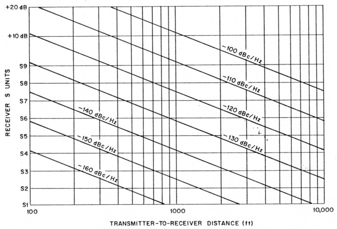
Fig 4-Phase-noise interference at 14 MHz as a function of the distance between transmitting and receiving antennas. The curves are based on a transmitter EIRP of 100 W and a receiving bandwidth of 2 kHz. The path loss from the transmit antenna to the receive antenna is assumed to follow the free-space attenuation curve. S9 is equivalent to 50 V.
Far-out phase noise in a receiver oscillator is less destructive, because it affects only the receiver in which it is generated. The net effect, however, is the same: Any signal that reaches a mixer in the receiver is modulated by the phase noise in the local oscillator driving that mixer. As such, the signal appears to have at least as much phase noise as the local oscillator. Thus, sufficiently strong signals off the receiving frequency can degrade receiver sensitivity by raising the noise floor at the receiving frequency. Receiver dynamic range is reduced as the noise floor rises.
As an example, suppose that a transmitter has a power output of 1 kW and an SSB phase noise of - 100 dBc/Hz at a given offset frequency. At that offset frequency, the transmitter radiates noise at a level of -40 dBm/Hz. In a 2-kHz bandwidth, this is equivalent to a noise level of -7 dBm, or 200 W. This is sufficient power to cause significant interference to local receivers. The effect on a receiver is the same as if the transmitter had low phase noise and the receiver had an SSB phase noise of -100 dBc/Hz. Fortunately, the oscillators in most amateur equipment don't have this much SSB phase noise at offset frequencies greater than a few kilohertz.
The effect of phase noise on an amateur communications system can be calculated with reasonable accuracy if a few simple assumptions are made. From the calculated effects, we can calculate the oscillator performance necessary to meet our requirements. The assumptions are:
- The transmitter is located 1 mile from the receiver.
- The EIRP (effective isotropic radiated power) of the transmitter is 100 W (+ 50 dBm).
- The loss from the transmit antenna to the receive antenna is the same as in free space. (This isn't strictly true for signals propagated above ground, but it gives an approximation of the expected signal attenuation. The actual attenuation is almost impossible to calculate because of the effects of the local terrain.)
- The receive antenna gain is 0 dBi in all directions.
- Our goal is phase-noise level that does not significantly degrade the performance of the communications system. That is, the received noise resulting from oscillator phase noise should be equal to or less than the background noise normally picked up by an antenna on a given amateur band. (Background noise is composed of radio emissions from our galaxy, as well as manmade noise and atmospheric noise, and varies with frequency.)
| 14 MHz | 144 MHz | |
|---|---|---|
| EIRP | +50 dBm | +50 dBm |
| Loss from transmitter to receiver (distance = 1 mile) | 60 dB | 80 dB |
| Signal power at receiving antenna (0-dBi gain receiving antenna) | -10 dBm | -30 dBm |
| Noise power at receiving antenna (background noise) | -150 dBm/Hz | -172 dBm/Hz |
| Equivalent SSB phase noise | -140 dBc/Hz | -142 dBc/Hz |
This table shows maximum phase-noise levels tolerable in a communications system before dynamic range is significantly degraded. In both cases, EIRP is 100 W; separation between transmitting and receiving antennas is 1 mile; the receiving antenna is omnidirectional and has 0 dBi gain; and the receiver is sensitive enough to detect the noise. At 14 MHz, path loss and received noise power allow the receiver to detect any phase noise stronger than -140 dBc/Hz. At 144 MHz, background noise is lower and path loss is higher, resulting in a tolerable equivalent phase-noise level of -142 dBc/Hz at this frequency. See text for additional information. | ||
Table 1 shows the results of these calculations. The table shows values for both 14 MHz (representative of the HF bands) and 144 MHz (representative of the VHF bands). As can be seen from these calculations, the phase noise must be less than -140 dBc/Hz if there is to be no noticeable interference. A higher EIRP or less transmitter-to-receiver antenna separation would require even better phase-noise performance to guarantee no significant interference. The graph of Fig 4 shows phase-noise interference generated at 14 MHz as a function of transmitter-to-receiver antenna separation, and the apparent SSB phase noise of the system. The interference level is plotted in S units, assuming S9 is equal to 50 µV and each S unit is 6 dB. As can be seen from the graph, an SSB phase noise of -120 dBc/Hz at a distance of 500 feet produces nearly an S9 signal. This graph may be applied to local situations to estimate the interference potential that could result from oscillator phase noise.
Phase Noise Levels in Amateur Equipment
Equipment cost limits the extent to which we can minimize phase noise in communications systems; with this in mind, we can set rough phase-noise performance standards for equipment in various price ranges.
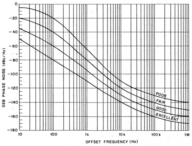
Curves showing my recommendations for such standards appear in Fig 5. These curves represent tools for comparison of phase-noise performance in amateur equipment. I derived them to give an overall idea of the phase-noise performance of amateur equipment.
These recommendations are shown by four curves: "excellent," "good," "fair" and "poor." When the phase-noise characteristics of a radio are known, they caxt..be compared to the curves in Fig 5. The worst curve that a radio's phase-noise characteristics pass through should be considered the performance of that radio. The "excellent" curve represents close to "state of the art" performance for HF and VHF synthesized oscillators. For amateur equipment, this curve is approached by free-running LC and crystal oscillators, and the very best transceivers.
The "good" curve represents what is achieved by most well-designed amateur equipment. It doesn't cost a great deal more to design a radio that meets this curve (as opposed to the "poor" or "fair" curves). A radio with phase-noise performance that only meets the "fair" curve hasn't been designed with much regard for minimizing phase noise. The "poor" curve represents a design that is so poor that a transmitter with this performance shouldn't be used on the amateur bands because of the great amount of interference it can generate.
The close-in phase-noise characteristics shown in the curves of Fig 5 are relatively easy for most oscillators to achieve. The close-in regions of the curves were derived mainly from the effects of IFM on the limiting FM SNR. Table 2 lists the close-in phase-noise IFM integrated from 10 Hz to 10 kHz for each of these curves. (Even a radio generating the IFM level corresponding to phase noise matching the "poor" curve provides adequate voice communications capability.)
Measuring Phase Noise
Equipment capable of measuring low levels of far-out phase noise is quite expensive. It is not unusual for commercial enterprises to invest $100,000 in good phase-noise measurement equipment. Inexpensive techniques are, however, available for measuring the apparent phase noise of communications receivers and transmitters. In Part 2 of this article, I'll describe the test setup I use to measure received phase noise. The method used by ARRL for measuring transmitted phase noise will also be discussed. [Because most modern transceivers use the same local oscillator and mixer chain on both trans mit and receive, overall phase-noise performance can be evaluated by measuring either transmitted or received phase noise-Ed.] The equipment necessary to measure receiver phase noise can be built by enterprising amateurs for well under $100.
APPENDIX
Manipulating Units of Measurement
Several of the units of measurement used in this article may be unfamiliar to many amateurs. Manipulation of some of these units is covered here.
Oscillator phase noise is converted to a power level per Hz [Pn(f)] by adding the SSB phase noise [L(f)] to the carrier power [Pc]. This is done by the equation
![]()
where the units are shown in braces.
Power level per Hz [Pn(f)] is converted to a power level [P) in a given bandwidth [Δf] by
![]()
where the units are shown in braces. This equation assumes that the power level per Hz is constant across the bandwidth.
Incidental Frequency Modulation
The incidental frequency modulation (IFM) resulting from the phase noise on an oscillator can be found by
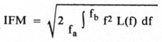
where L(f) is the SSB phase noise converted from dBc/Hz to relative power per Hz, and fa and fb are the lower and upper frequency limits of the communication bandwidth. (For amateur FM operations, the communication bandwidth is typically between 100 Hz and 5 kHz.)
An approximation of the limiting signal-to-noise ratio in dB can then be defined (using IFM) as
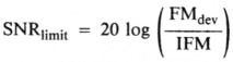
where FMdev is the RMS deviation of the FM signal. This equation yields only an approximation because it doesn't take into account the effects of preemphasis or deemphasis in the FM system, nor the spectral distribution of the modulating signal. (This equation generally yields results that are within a few dB of the actual numbers we would find if we took the trouble to include the other effects.)
The limiting SNR effects on a VHF amateur communications system can be found as shown in the following example. Let's assume the apparent phase noise in a communications system is -40 dBc/Hz at a 100-Hz offset frequency, and decreases to - 74 dBc/Hz at a 5-kHz offset frequency. The resulting IFM is 100 Hz. This is not very good performance for synthesized oscillators, even at VHF. If we now assume that the RMS deviation of the FM signal is 5 kHz, the maximum SNR that can be achieved in this system is 34 dB, which is more than adequate for voice communications.
| Curve | IFM |
|---|---|
| Excellent | 0.4 Hz |
| Good | 2.5 Hz |
| Fair | 20 Hz |
| Poor | 160 Hz |
| Incidental frequency modulation (IFM) resulting from the phase-noise levels shown in Fig 5. The IFM was calculated for the frequency range from 10 Hz to 10 kHz. | |
Phase-noise photographs from the ARRL lab
The photographs in this section show phase-noise characteristics of several common amateur transmitters. These photos were taken in the ARRL laboratory using procedures developed by Laboratory Engineer Zack Lau, KH6CP. The technique involves mixing the RF output of a Hewlett-Packard 8640B signal generator with the attenuated output of the transmitter under test. (Details of the test setup will be given in Part 2 of this article.)
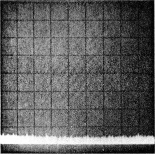
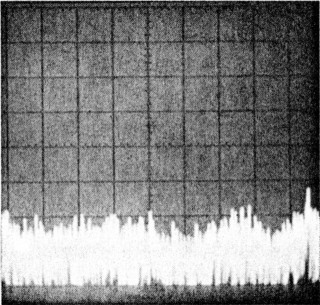
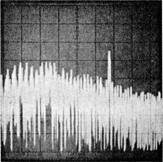
The scale on the spectrum analyzer on which these photos were taken is calibrated so the base line in the photographs represents - 140 dBc/Hz. Vertical divisions are 10 dB, and horizontal divisions are 2 kHz. The horizontal scale covers offset frequencies from 2 kHz to 20 kHz. Phase-noise levels can be read in dBc/Hz directly from the photographs.
The photos presented here were chosen because they are representative of the equipment available on the amateur market, although these photos do not necessarily reflect the phase-noise characteristics of all units of a particular model. Photo A, which shows the phase-noise characteristics of the HP 8640B RF signal generator, serves two purposes: It shows excellent phase-noise characteristics, and it shows the measurement limits of the ARRL test setup. (We hope to have much greater measurement capability in the near future, but this system allows measurement of all but the most phase-quiet signals.)
NJ2L, Rus Healy
 |
 |
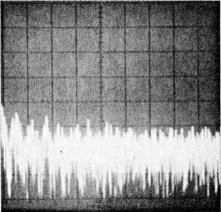 |
| Photo A-HP 8640B RF signal generator (serial number 2044A15060) phase-noise 1 characteristics. This photo was taken using a second '8640B as a local oscillator. This photograph shows the measurement limits of the system used to measure transmitter phase noise in the ARRL lab. | Photo B-ICOM IC-751A (serial number 01043) phase-noise characteristics. Measurement frequency: 14 MHz, power output: 102 W. | Photo C-Kenwood TS-930S (serial number 7080033) phase-noise characteristics. Measurement frequency: 7 MHz, power output: 91 W. |
 | 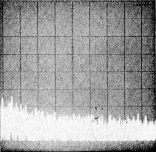 | |
| Photo D-Yaesu FT-767GX (serial number 6J030740) phase-noise characteristics. Measurement frequency: 14 MHz, power output: 95 W. | Photo E-Ten Tec Argonaut 515 (serial number 515-0533) phase-noise characteristics. Measurement frequency: 14 MHz, power output: 5 W. |
KI6WX, John Grebenkemper.
1 - 2