A simple tuning indicator
If your modem lacks a tuning indicator, this unit may be just what you've been looking for! It's the perfect mate to the Cheap n' Easy Modem.
Received RTTY signals must be tuned in correctly for a modem to function properly. Experienced operators can usually tune in a signal by ear, but those of us who are new to RTTY (or those who are tone deaf) often need some help to get the audio tones exactly right. A visual indication of proper tuning is a big help.
The tuning indicator we're about to describe is compact and inexpensive. Though designed to be part of the Cheap n' Easy Modem described last month, it can be adapted to work with other modems, requiring only a source of audio and ± 12 V at 100 mA.
Circuit description
The schematic diagram of the tuning indicator is shown in Fig 1. Incoming audio is fed to U1, an LM565 PLL. This IC produces a square-wave output signal, which is locked to the input frequency. U1's output is applied to U2, an NE555 timer. At U2, R12 and C12 create a time window outside of which there is no output from U2. The output of U2 consists of variable-width negative-going pulses with widths proportional to the input frequency. These pulses are fed to Q7.
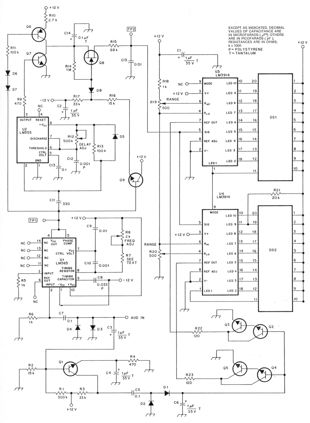
Fig 1 - Schematic diagram of the LED tuning indicator. All resistors are 1/4-W, 5% tolerance unless otherwise noted. Capacitors can be ceramic or electrolytic types. If electrolytics are used, observe polarity as shown. (Note: Equivalent parts may be substituted.)
| C8 | 0.033 µF polystyrene |
| C12 | 0.001 µF polystyrene |
| C14 | 0.1 µF tantalum |
| D1-D8 | 1N914 silicon diode |
| DS1, DS2 | Dot/bar LED display (Radio Shack 276-081 or equiv) |
| Q1-Q5, Q7, Q9 | 2N3904 |
| Q6 | 2N3906 |
| Q8 | 2N5484 |
| R7 | See table 1 |
| R8 | 2-kΩ, 10-turn trimmer |
| R12 | 500-kΩ 10-turn trimmer |
| R19, R20 | 500-Ω, 1-turn trimmer |
| U1 | LM565 PLL |
| U2 | NE555 or LM555 timer |
| U3, U4 | LM3914 dot/bar driver |
U1's output is also applied to Q6. C14 charges (through Q6 and R10) during the more negative part of the square-wave output cycle. The time that C14 is allowed to charge is inversely proportional to the frequency of the applied square wave, so the peak voltage across C14 is inversely proportional to the incoming frequency.
Q8 and Q9 form a sample-and-hold cir cuit that samples the voltage on C14 at the moment of peak charge and stores the sample in C15.
U3 and U4 are LM3914 dot/bar LED drivers. The threshold and range of the drivers are adjusted by means of R19 and R20. The voltage across C15 is fed to this circuit, which lights one of 20 LEDs contained in the combination of DS1 and DS2. Which LED is lit is determined by the frequency of the incoming signal; mark and space tones light specific LEDs. The receiver is properly tuned when the two illuminated LEDs are spaced equally from the center of the display.
Q1 through Q5 form a visual squelch circuit. Q1 is biased slightly below cutoff. When the voltage level of the incoming signal reaches 50 mV (typical), Q1 begins to conduct, amplifying the incoming signal. D1 and D2 rectify the signal voltage, and the dc output from these diodes is used to switch on the Darlington pairs, Q2-Q3 and Q4-Q5. These transistor pairs are connected to the REFERENCE OUTPUT control pins of the LM3914 drivers to control display brightness. The LEDs are off when there is no input signal present. RI's value can be tailored to change the sensitivity of the squelch circuit. Increasing the value of RI will make QI less sensitive.
Construction
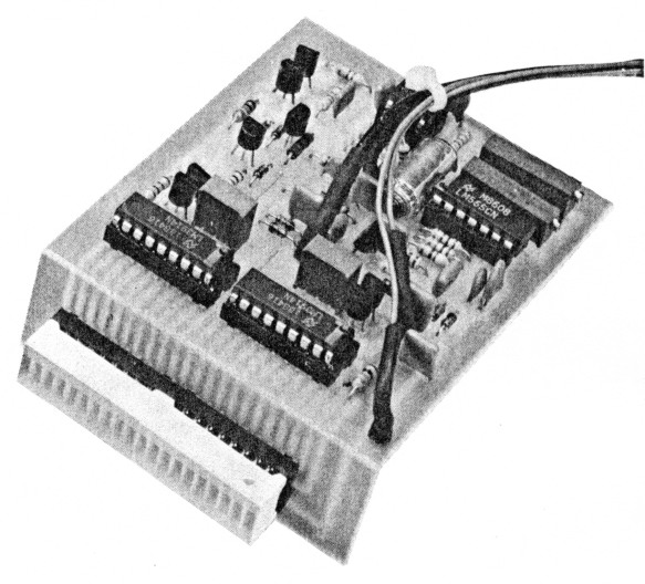
Figs 2 and 3 show the PC board etching pattern and parts overlay, respectively. In Fig 4, you can see the tuning indicator mounted in the Cheap n' Easy modem described last month. The PC board is designed to allow you to use several different methods to mount the LEDs. For instance, you may detach the LED section from the rest of the board (at the point marked by the arrow in Fig 3), then use ribbon cable for the interconnections. Or, the LED mounting area can also be soldered to the main board at a right angle; this method is shown in the title photo and in Fig 5. Remember to cut the LED section of the board from the main board before mounting any components!
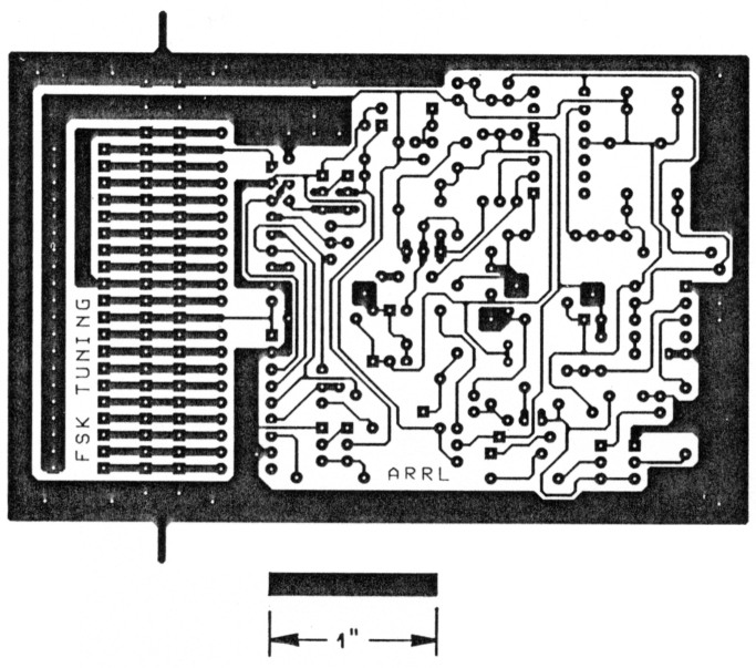
Fig 2 - Circuit-board etching pattern for the tuning indicator. The pattern is shown full-size from the foil side of the board. Black areas represent unetched copper foil.
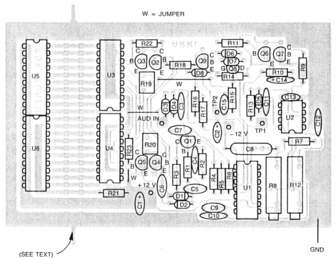
Fig 3 - Parts-placement guide for the tuning indicator. Parts are placed on the nonfoil side of the board; the shaded area represents an X-ray view of the copper pattern. Note the jumpers (W) required; these should be installed first. The arrow points to the junction at which the board may be separated (see text).
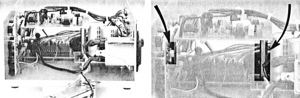
Fig 4 - The power transformer of the Cheap n' Easy Modem has been removed to show how the LED tuning indicator is mounted. The arrows indicate the positions of two of the three supporting spacers. A metal spacer attached to the power-supply board supports the rear of the tuning indicator board. Two spacers (only a portion of one is visible here) and mounting hardware secure each side of the board to the front panel.
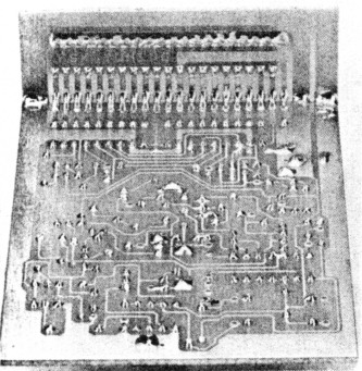
Fig 5 - A foil-side view of the tuning indicator board showing how the right-angle joint is made.
In the Cheap n' Easy Modem, the front edge of the tuning display is supported by two screws that pass through the front panel. The bottom edge of the LED panel is secured by these two screws and two spacers. This hardware (use no. 4-40 or 2-56) must be secured to the ground foil that runs around the outer edge of the PC board (see the marked area on the parts overlay in Fig 3). Make sure the hardware does not short to any other trace.
The rear of the display is supported by a spacer soldered to the display circuit-board foil and attached to the modem's rectifier/filter board. (This is the reason for the "extra" hole in that board that we spoke of last month.) Another spacer between the bottom of the rectifier/filter board supports it from the bottom of the enclosure.
All of the capacitor and 10-turn potentiometer mounting areas have extra holes to accommodate components of different sizes and styles. The majority of the capacitors can be ceramic or electrolytic, but C8, C12 and C14 must be high-quality capacitors. We found that polystyrene capacitors worked well for C8 and C12; a tantalum capacitor is used at C14. We used 10-ohm, ¼W resistors for the test points, but these could be pieces of bare wire or PC-board pins. Don't forget to install the three wire jumpers (marked W in Fig 3).
Calibration
The calibration procedures have been tried using the most common tone frequencies and shifts (see Table 1). Note that the value of R7 must be changed for each shift value. This dictates that the tuning indicator must be calibrated for one shift and used only for that shift. An audio-frequency counter, voltmeter and audio oscillator are required to calibrate the tuning indicator.
| Lo Tone (Hz) | Hi Tone (Hz) | F0 (Hz) | Fshift (Hz) | Data Rate (Bauds) | R7 (kilohms) |
|---|---|---|---|---|---|
| 2125 | 2295 | 2210 | 170 | 110 | 3.3 |
| 2125 | 2550 | 2337.5 | 425 | 300 | 3.3 |
| 2125 | 2975 | 2550 | 250 | 300 | 2.7 |
| 1615 | 1785 | 1700 | 170 | 110 | 4.7 |
| 1275 | 1445 | 1350 | 170 | 110 | 5.6 |
Adjust R8 and R12 fully counterclockwise. Adjust R19 and R20 to the center of their range. Ensure that the value of R7 is correct for the desired frequency and shift. Apply power to the tuning indicator. Connect the frequency counter to TP1. With no audio signal applied, adjust R8 until the counter reads Fo (see Table 1).
Connect the voltmeter to TP2. Apply a 1-V signal at Fo to the input. (Use the frequency counter to aid in adjusting the oscillator to the proper input frequency.) Adjust R12 until the voltmeter reads 2.5 V, then disconnect the voltmeter. One of the LEDs should be lit. If not, try adjusting R 19 and R20 until any segment is lit. Once a segment lights, adjust R12 until the segments on DS1 and DS2 either side of center flicker. If none of the segments light, be sure that the displays are installed correctly. We found some discrepancies in the way pin 1 of the LED displays is identified by different manufacturers.
Set the audio oscillator frequency to Lo Tone. Adjust R20 until the fifth segment of DS1 is lit. Tune the oscillator to the Hi Tone frequency. Adjust R20 until the fifth segment of DS2 is illuminated. The adjustments of R12, R19 and R20 interact, so it is necessary to repeat the sequence of adjustments until no further improvement can be obtained.
Summary
The PC board is designed to be mounted a variety of ways. This should make it easy for you to adapt the tuning indicator for your use. Whether you use this tuning indicator with the Cheap n' Easy Modem, or one of your own design, you'll find it an invaluable aid in correctly tuning RTTY signals.
NK1P, Tom Miller and KA1CV, Ed Hare.