A multipurpose DTMF encoder
This encoder uses readily available parts, fits into a handy audio console and is perfect for mobile installations.
Having four FM transceivers in one vehicle presents some interesting challenges. I had to find a way to keep track of each microphone: Each has different dual-tone multi-frequency (DTMF) capabilities to access the local repeaters. Rather than use four encoders, I searched the literature for an easier way. I came across the CD22859E, a DTMF tone generator IC manufactured by RCA. Two versions are available: the CD22859E and the SK22859E. I learned that the CD version is the less expensive, selling for $5 in small quantities, but there is no readily available application information. With over-the-phone assistance from the technical staff at RCA, the encoder circuit shown in Fig 1 was developed.
The Encoder Circuit
The CD22859E is easy to work with. It delivers a constant output, supplying voltages from 4 to 13. A simple voltage divider reduces the supply voltage and regulates it. A small capacitor filters the supply for reliable operation.
Parts layout of the encoder circuit is not critical. My DTMF encoder is built on the PC board of a DigiTel" keypad from a discarded ITT® telephone, but the circuit can also be fabricated on perfboard. All the original components, except the 3.579-MHz crystal and most circuit traces, were removed from the board. There were ample fioles in the board to mount the components, and I made the electrical connections using point-to-point wiring. The board also contained a socket that mated with the DTMF pad. This was left intact. A 16-pin socket was added to accommodate the CD22859E. The CD22859E has the same pinout as the 18-pin chip on the keypad, but because it is a 16-pin device, pins 1 and 18 are not used.
Fig 1 shows two circuits. The left half is the encoder circuit. The right half shows a transmitter-keying circuit that uses one of two keying control voltages. Any keystroke causes one of these voltages to actuate the keying circuit. The key-up circuit was patterned after one in "The 1988 ARRL Handbook" It has a two-second hold time that can be increased by increasing the value of C4. A keying relay is included, although the transistor is capable of keying most any solid-state or relay-type circuit. The keying relay provides the ground for the key line.
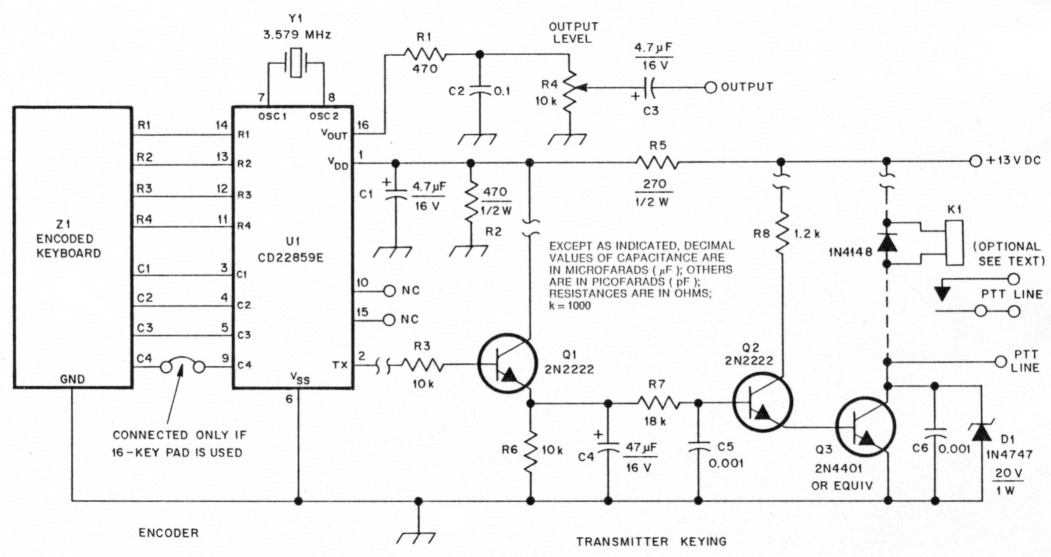
Fig 1 - Schematic of the DTMF encoder with transmitter keying. Resistors are 1/4-W, carbon-film units unless otherwise noted. If direct control of the PTT line is desired, connect the PTT line to the collector of Q3. If relay control is needed, add a relay and tie the top end to the collector of Q3. Do not use both options at the same time.
| D1 | 20-V, 1-W Zener (1N4747 or equiv). |
| Q1, Q2 | General-purpose NPN transistor (2N2222 NPN or equiv). |
| Q3 | General-purpose NPN transistor (2N4401 NPN or equiv). |
| K1 | Relay, 12-V solenoid. |
| Z1 | DTMF encoder keyboard. The keypad used in this project was made by DigiTel, but the circuit can be built on any type of circuit board. |
My encoder is one of several circuits inside an audio console that handles all mic, DTMF and keying functions for the four rigs in my vehicle. The two-second hold time allows entry of a DTMF code .....
The Audio Console
The DTMF encoder is the central building block for an audio console that has been in operation in my vehicle for almost one year. The console helps prevent extra microphones from getting in the way. The ponsole provides a handy way to run multiple rigs at the same time.
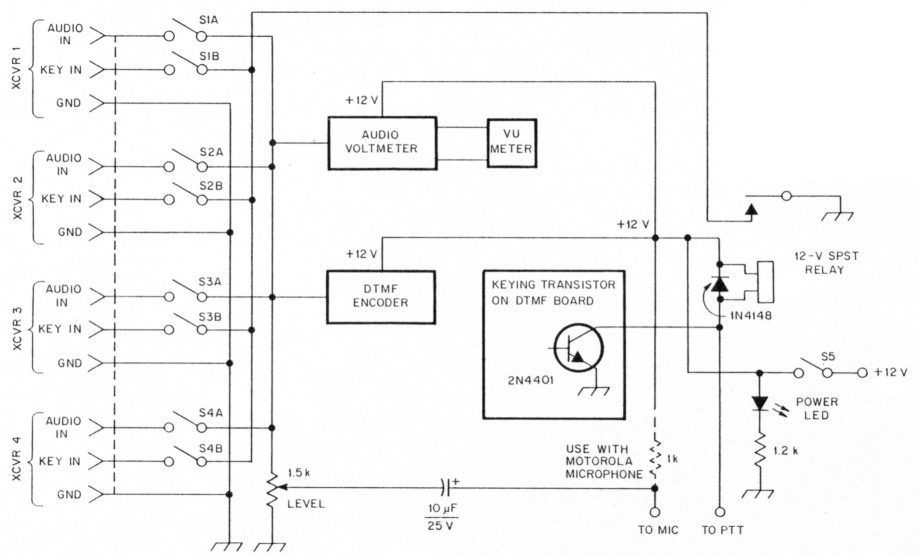
Fig A - Diagram of the mobile audio console.
Fig A shows a diagram of the console; it can be tailored to satisfy any need. Fig B shows the front panel of the finished unit. My console consists of a single Motorola microphone, an audio bus and a key-line bus that can be easily switched into the circuit. The audio voltmeter circuit came from Solid State Design for the Radio Amateur.t It serves as an extra "bell" that comes in handy. The VU meter is from an old audio cassette player, and allows me to monitor the audio output visually. To use the console, I flip the switch to channel microphone audio, keypad capabilities or keying to the rig I choose to operate. It is possible to key all four rigs simultaneously, but I do not recommend this.
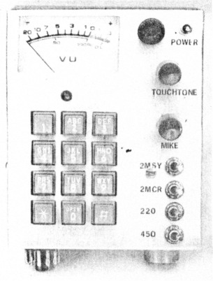
Fig B - The finished mobile audio console. The unit feeds audio and control signals to four rigs, which can be selected by miniature toggle switches. The 11-pin plug on the bottom left feeds audio and control voltages to each rig. The jack on the right accommodates a microphone. The meter is from a junked stereo tape deck. Front-panel gain controls make fine tuning of the audio easy.
All microphone and keying-line connections from the toggle switches are brought to an 11-pin chassis-mounted plug on the bottom of the console case. The case is homemade from a single piece of aluminum, and the dimensions will vary, depending on its contents.
My audio console case is mounted to the left of my vehicle's steering wheel. The console is mounted between the dash panel instrument section and the dash padding. A couple of ears mounted on the back of the case slip into the cracks in the dash panel above the speedometer assembly. Any mounting system can be used.
The ease of operation afforded by the audio console made its construction worthwhile. The capability of your console is limited only by your junk box and imagination.
W9OBG/7, Walter Boller.