Evolution of the short top-loaded vertical
If a quarter-wave vertical for 160 meters is beyond your means, how about trying something shorter?
On 160 meters, "the gentleman's band," many hams operate short base- or top-loaded verticals. They use an antenna length (height) of about 30 to 60 feet with modest radial systems. Their available space, height restrictions or finances simply do not permit installing the traditional ¼-λ tower and a system of 120 ¼-λ radial wires that approaches an efficiency of 100%. The name of the game is, "Make the most of what you have."
For purposes of discussion, I will use a 40-foot mast of 1.6-inch average diameter and a frequency of 1.9 MHz as the basis for various short vertical antennas. Differences between the field pattern of such a short vertical and that of a ¼-λ vertical over the customary "perfect earth" are almost indistinguishable unless the patterns are superimposed. See Fig 1A. The ¼-λ radiator is very slightly better at the lower angles and the 40-foot radiator is very slightly better at the higher angles.
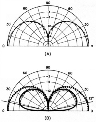
Fig 1 - At A, the E-field patterns of a ¼-λ antenna and a short antenna differ only slightly over perfect earth. For equal radiated power, the similarity is also present over real earth, as shown at B. Over real earth, both patterns are down by approximately 6 dB from the perfect-earth field value at the psuedo-Brewster angle of 12° - poor earth conditions typical of the suburban backyard surrounded by houses. (Patterns calculated with MN).
Solid lines - Patterns for a short vertical antenna.
Broken lines - Patterns for a ¼-λ 160-m vertical antenna.
Dotted lines - Pattern for a ¼-λ antenna over perfect earth.
Over real earth, with enough input power to each antenna to produce equal radiated power, the patterns will again be essentially the same, and look like those of Fig 1B. Aside from questions of efficiency, the antenna patterns should be similar for the same location.
Over real earth with a modest radial system of 10 to 20 radials, each of perhaps 35 or so feet in length, antennas in various locations will not all see exactly the same ground-loss resistance. For purposes of discussion, let's assume it to be 15 ohms - recognizing that the typical short antenna is seldom found on the "average earth," that is, in a meadow accommodating an extensive radial system. This figure is derived largely by experience with suburban backyard antenna systems. This ground-loss resistance (Rg) will appear at the feed point of each antenna in series with the radiation resistance (Rr) and any other loss resistance.
For those interested in the mathematics or in designing for a somewhat different antenna height, etc, the equations used in this discussion are given in the Appendix. There are many formulas and curves for radiation resistance, Rr, versus vertical height of the antennas discussed here. Accurate formulas are tedious of solution (see Appendix Eq 1) and accurate simple formulas are restricted to narrow height ranges. Appendix Eq 2, however, applies to simple vertical monopoles with acceptable accuracy for our purposes up to heights of 90°. Rr is virtually independent of radiator diameter within any practical diameter range of these antennas.
The various antennas to be discussed are shown in Fig 2. The sinusoidally distributed currents are shown to scale. The value of the base current for 100 W input to the antenna is listed as Ib. At 1 kW, it would be 3.16 times that value.
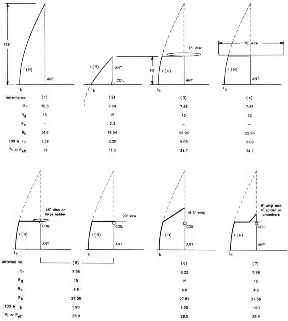
Fig 2 - The antennas described in the text are shown with their current distributions, radiation resistances Rr, assumed ground-loss resistances Rg, coil loss resistances Rc (if any), total base input resistances at resonance Rb, base currents Ib for 100 W input to the antenna, and efficiency in percent. The efficiency percentage is the same as the radiated power in watts.
Antenna 1 - The ¼-λ vertical
By definition, a ¼-λ antenna has an electrical length (height) of 90°. Rr by Eq 2 is the conventional 36.6 ohms. In series with the assumed Rg of 15 ohms, a feed-point resistance Rb of 51.6 ohms results. Because efficiency is the ratio of Rr to the total feed-point resistance including all losses (Eq 4), an efficiency of 71% is indicated. These data are listed in Fig 2 under Antenna 1.
Antenna 2 - The short base-loaded vertical
A 40-foot vertical has an angular height of 27.8° (Eq 3) and Rr of 2.24 ohms (Eq 2) at 1.9 MHz. Being short of ¼-λ resonance, it exhibits capacitive reactance as part of its feed-point impedance. The capacitive reactance can be computed by viewing the antenna from the base as a transmission line terminated in an open circuit. The characteristic impedance of this "line" for the 40-foot height and 1.6-inch diameter is calculated as 365 ohms from Eq 5. Its input reactance, using Eq 6, will be -j692 ohms. This capacitive reactance can be canceled by a base-loading coil with an inductive reactance of +j692 ohms. This requires an inductance of 58 µH (Eq 7). If the 58-µH coil has a Q of say, 300, its loss resistance, Rc, will be 2.3 ohms (Eq 8), which will appear at the base in series with the Rg of 15 ohms and the Rr of 2.24 ohms for a total Rb of 19.54 ohms. Efficiency (Eq 4) is 11.5%. Note the triangular current distribution. The loss in any required L network to match these antennas to a 50-ohm coax feed line is assumed negligible.
We can expect the signals from this 40-foot base-loaded antenna to be down about 8 dB (Eq 9) from a full ¼-λ antenna in the same location with the same ground-loss resistance.(1) Of course, very few ¼-λ towers are so situated.
The ground loss is the thing which we must endure since we can do little to change it in limited space for a radial system. The other factor, Rr, however, is something we can change.
Antenna 3 - capacitive top loading
At higher frequencies, a capacitive top hat is often used to increase the radiation resistance of a short antenna and bring it to ¼-λ resonance. This would eliminate the need for the base loading coil with its 2.3 ohms of loss resistance. The radiation resistance of the base section of a 40-foot top-loaded vertical can be calculated by Eq 1, but again a simpler equation (Eq 10) yields values sufficiently accurate for our purposes. For this antenna an Rr of 7.96 ohms results. This increases efficiency to 34.7% for a gain of 4.8 dB over the base-loaded system.
Shown in Fig 2 as Antenna 3, the improvement can also be seen as the change in current distribution compared with that of Antenna 2. The current times the length is the area under the current curve along the antenna. Power radiation is proportional to the square of this area, so the power radiated by Antenna 3 is 3 times that of Antenna 2 for the same input power - a gain of about 4.8 dB.
The top loading seemingly replaces the antenna portion and current distribution shown in broken lines. Therefore, some interpret top loading as increasing the effective height of an antenna. The top-loaded antenna, however, will not have the R, implied by its ¼-λ resonance.
The 40-foot mast, viewed figuratively from the top as a 365-ohm transmission line, appears as a short-circuited line. The bottom end is terminated in an impedance that is very low compared to its characteristic impedance. Using Eq 11, a short-circuited line that is 27.8° long with a Z0 of 365 ohms has an input impedance of j192 ohms. A capacitive reactance of 192 ohms would bring it to resonance. The corresponding capacitance is 436 pF by Eq 12.
A solid thin disc provides just about the highest capacitance available for a given area. Depending on the method used to calculate the disc size, it will be approximately 15 feet in diameter. The customary equation used to calculate the capacitance of a disc (Eq 13) is not applicable to such a large disc only 40 feet above the ground. At any rate, a purely capacitive top load seems impractical for such a short antenna at this frequency.
An intermediate arrangement could be a reasonably sized capacitive hat on Antenna 2. This would somewhat increase the antenna R, and somewhat decrease the base inductance required to resonate it, resulting in improved efficiency over Antenna 2.
Antenna 4 - the wire flattop
A horizontal wire flattop can be used to bring the 40-foot mast to ¼-λ resonance. As shown for Antenna 4, the center of the wire is connected to the top of the mast. Equal currents flowing outward cancel almost all radiation from the flattop. To bring a short antenna to ¼-λ resonance, the wire length should be about twice the length of the missing angular length. In this case, at 1.9 MHz, that length is approximately 2 x (90° - 27.8°) = 124° or 178 feet. This is 89 feet of wire on each side connected to the top of the 40-foot mast. But 178-foot flattops are not usually possible in this environment. Drooping the flattop wires eliminates the two end-supporting masts, but does not reduce the space required by a significant amount. It produces a downward-flowing current component which is in opposition to the current in the mast, slightly reducing R, A long but somewhat narrow space may accommodate such a flattop, and efficiency of 34.7% would be effected.
Good quality insulators must be used at the wire ends because of the rather high voltages present. Strain insulators ordinarily used in guy wires will not do.
The wire flattop is a cousin to the inverted L, which is really not a top-loaded vertical but an antenna that is a combination of vertical and horizontal elements.
Antenna 5 - the inductive-capacitive top load
The 7.96-ohm R, of the top-loaded antenna still looks attractive. If an inductive reactance is placed in series with a capacitive reactance, it reduces the effective capacitive reactance. Inductive reactance can make a small capacitance (high reactance) look like a large capacitance (lower reactance), as shown by Eq 14.
If a more practical hat size, say 48 inches in diameter, is postulated, its capacitance as calculated from Eq 13 is about 43 pF. Its reactance is -j1946 ohms (Eq 15). As previously calculated, the inductive reactance of the mast as seen from the top is +j192 ohms, leaving 1946 - 192 = 1754 ohms to be supplied by the inductor. From Eq 16, this is 147 µH, a feasible coil. Assuming that a Q of 300 is reasonable, then the coil loss resistance given by Eq 8 is 5.85 ohms.
This 5.85 ohms of resistance is located at the top of the mast. Because the current is sinusoidally distributed, the current at an angular distance from the current loop (at the base in a ¼-λ resonant antenna) is the loop current multiplied by the cosine of the angular distance from the loop. Since P = I2R, we can "refer the resistance to the loop" by multiplying it by cos2θ, Eq 17. Since the cosine of θ decreases with antenna height, taller antennas reflect less of the coil resistance to the base.
For the 27.8° mast, Eq 17 refers the 5.85 ohms to the feed point as 4.6 ohms, a loss resistance that becomes part of Rb. With Rr of 7.96 and Rb of 7.96 + 4.6 + 15 = 27.56 ohms, efficiency by Eq 5 is 28.9%.
A gain of 4.0 dB has been achieved over the base-loaded antenna, Antenna 2. Don't sniff at 4 dB! Some hams put up two-element phased arrays to achieve 4 dB of gain.
A 20-foot or so wire flattop of no. 10 wire with its center connected to the top of the loading coil could serve the same purpose as the 48-inch disc. Such an arrangement is essentially the wire flattop of Antenna 4 shortened by the action of the loading coil.
Wire lengths intermediate to the 178 feet of Antenna 4 and the 20 feet above could be resonated by progressively larger inductors, with space considerations or coil power loss determining the length of the wire. The same precautions regarding insulators apply. Tuning could be accomplished by pruning the wire length. Sloping the wire will change the tuning, because it affects the capacitance to ground.
Antenna 6 - inductive-capacitive top loads with whips
Another common technique is to use a whip above a loading inductor in a vertical antenna, such as in center loading or above-center loading. A whip as seen from the inductor can be treated as an open-circuited transmission line.
Assume a 15.5-foot whip with an average diameter of 0.562 inch (1 inch tapering to 1/8 inch). Anything longer seems rather difficult to support without guying somewhere above the coil. This is difficult because very high voltages are present on the top-loading coil and all parts of capacitive structures above the coil.
Eq 3 gives the whip angular length as 10.78 °. The Z0 is 371 ohms by Eq 5. The mast provides 192 ohms of inductive reactance as previously calculated. Eqs 6, 14 and 7 yield an inductance of 147 µH.
Assuming again a Q of 300, the same 4.6 ohms is referred to the base. The coil requirement of the 15.5-foot whip is exactly the same as that of the 48-inch disc. The whip, however, contributes to the Rr. Eq 2 applies and yields 0.33 ohm of radiation resistance at a point 27.8° above the base. Eq 17 refers it to the base as 0.26 ohm of Rr, which adds to the 7.96 ohms for the mast section for a total Rr of 8.22 ohms. The efficiency by Eq 4 is 29.5%. The gain over the base-loaded antenna is 4.1 dB, not significantly different from that of Antenna 5 using the disc.
The question often arises as to how much the whip contributes to radiation. This 15.5-foot whip, which is a fairly extreme whip length, atop a 40-foot mast and coil, contributes only 0.26 ohm to the total of 8.22 ohms Rr or 3%. Hence, only 3% of the radiated power comes from the whip in spite of its representing 28% of the overall height of 55.5 feet. For all practical purposes the mast does the radiating while the whip merely supplies its reactance to resonate the system. Most properly, a whip-loaded antenna height in this mast height range is that of the mast.
Under the assumptions made, the inductive-capacitive top-loaded antennas, 5 and 6, should provide signals about 4 dB down from a ¼-λ antenna in the same location with the same ground-loss resistance.
Capacitive structures
The capacitive structures described represent just about the largest disc or whip that is manageable, although I once heard a Texas station (where else?) with a hat made of 24-foot crossed sections of irrigation tubing with wires connecting the ends and the midpoints. Whips of generous diameter can be combined with rather long crossbars or spiders with enough legs to approach the capacitance of a disc for a more manageable and practical capacitive structure.
Whips and spiders or crossbars seem to add their capacitance fairly well, but no combination is equal to the sum of the capacitance of its parts. The larger the hat just above the coil, the less the whip contributes.
Antenna 7 of Fig 2 illustrates the current distribution of a combined capacitive hat and whip antenna. The combination has an effective combined capacitance of 43 pF, requiring the same 147 µH of inductive reactance. Its characteristics are similar to those of Antennas 5 and 6.
Bandwidth
The inductive-capacitive top-loaded antenna described will exhibit bandwidths of approximately 20 kHz between the 2:1 SWR points. If other than fixed-frequency operation is planned, then it is best to design and trim for a natural resonance at 2 MHz and use a small base coil to move around the band. A variable inductor of about 30 µH should provide for tuning down from 2 MHz to 1.8 MHz. I use a remotely switched motor-driven inductor.
Reduction of loss will decrease the bandwidth. The limiting case of essentially no ground loss would probably yield a bandwidth of about 10 kHz, but then other problems become quite severe.
Effect of coil loss
Larger, higher capacitance structures reduce the inductance requirements. Heroic structures are required to get the required inductance down to the 80-µH range.
Because of the swamping effect of the assumed 15-ohm Rg, loss in a top-loading coil has surprisingly little effect on efficiency over a rather large loss range. With 100 W to the antenna, loss in the 147-µH coil with a Q of 300 would be 13 W, and the peak potential across the coil about 4000 volts. This is quite acceptable for coils of modest size and construction.
Operation of antennas such as Antenna 7 at the legal limit of 1500W to the antenna would produce power loss in the coil of 250 W and peak coil voltage of 20,000. While the 250 W would average out to rather modest levels for SSB operation, the peak voltage would still exist. Under "key-down" or AM operation, the 250-watt level would be catastrophic to coils of the usual size and construction. For legal-limit input, the top-loading structure will have to be such as to require less inductance, or the coil will have to be designed for a substantially higher Q, or both.
For example, say a coil could safely dissipate a power on the order of 150 W. This is probably possible for a good-sized coil in an open-air environment. If so, then coils ranging from 80 µH with a Q of 300 (requiring very large capacitive structures) to 150 µH with a Q of 600 (requiring the reasonable structures of Antenna 7) will survive.
The alternative is to ensure that the duration of such power input never exceeds some brief time well within the thermal time constant of the coil - a risky procedure at best. Stories of burning or melting top-loading coils are not uncommon.
Effects of ground-loss reduction
The efficiency of these short top coil-loaded antennas is improved with reduction of ground loss. An extensive radial system and earth of good quality produces a loss resistance of about 2 ohms. Over such a ground system, Antenna 7, with a 147-µH coil of Q = 300, will have an efficiency of almost 54%, for a signal increase of 2.5 dB. Although hardly worth the effort, this is possible because at a 100-watt power level the coil loss would be about 32 W.
Operation of this same antenna over such a ground system at 1500 W would lead to a coil loss of 475 W and 20,000 volts across the coil. Even a 147-µH coil with a Q of 600, which is quite hard to achieve in practice, would have to dissipate 300 W. An 80-µH coil with its attendant capacitive structure problem would dissipate 150 W. In summary, high-power operation of these short inductive-capacitive 160-meter antennas over good ground systems is limited by coil heat dissipation and voltages. The baseloaded vertical, with its loading coil at ground level, makes exotic coils possible, but the better solution is Antenna 4, the T with the horizontal-wire top load. Antenna 5, using a wire flattop of intermediate length, could reduce loading-coil requirements to a range of permissible loss, with space requirements being the trade-off.
The best article on ground radial systems that I have seen in amateur literature is one by Brian Edward, N2MF.(2) His Fig 7 is particularly applicable to ground systems of the kind likely to exist under the space limitations in which short antennas are often situated.
Vertical antennas are sometimes "low tuned" by top loading to raise the current loop farther above ground to reduce ground losses. In a short antenna, the angular distance just is not there to allow much current difference, and the required larger and hence more lossy inductor incurs additional coil loss that may exceed the ground-loss reduction.
The antennas discussed are all assumed to be base fed. Grounded towers can be top loaded to facilitate shunt feed or slant-wire feed. Short folded monopoles, folded umbrellas etc on grounded masts can also be top loaded. Although these feed methods yield a different (usually higher) feed-point impedance, this transformation of impedances does not affect the ground currents or ground losses of the antenna. Such currents and losses will be the same as they would be if the tower was isolated from ground at the base and fed at that point.
Conclusions
Short inductive-capacitive top-loaded antennas are suitable for operation under the conditions assumed. Coil loss is the compromise to space considerations, and the limiting factor for high power operation.
Coil-loss problems decrease with increased mast height or the availability of horizontal space for such as horizontal-wire top-capacitive structures. Reduction of coil loss will improve efficiency to some extent and permit operation at higher power levels.
Very low-loss ground systems, although improving efficiency for low-power opera tion, place prohibitive requirements on the loading coils for even large whip and spider capacitive structures. Survival of conventional loading coils with high power input is most probably because of very high ground loss.
Appendix
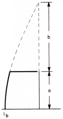
Fig 3 - Showing how lengths a and b are defined for Eq 1 of the Appendix. The total length (height), a plus b, equals 90°.
where
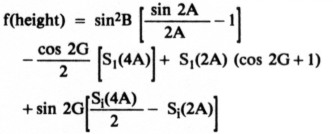
A = 2πa/λ
B = 2πb/λ
a = length a, feet (see Fig 3)
b = length b, feet (see Fig 3)
![]()
G = A + B
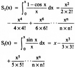
S1 and Si must be to about six-place accuracy for short antennas
where
Rr = radiation resistance of simple monopole, ohms
H = angular height of simple monopole
![]()
where
H = angular length, degrees; Note: 360/984 = 0.366
h = length, feet
f = frequency, MHz
![]()
where
Eff = efficiency, %
Rr = radiation resistance, ohms
Rb = total feed-point resistance, ohms
![]()
where
Z0 = characteristic impedance of vertical monopole considered as a transmission line, ohms
h = height of monopole, feet
d = average diameter of monopole, inches
In = natural logarithm
![]()
where
Zoc = input impedance of open-circuited line, ohms
Z0 = characteristic impedance of line, ohms
θ = angular length of line
j = the complex operator
![]()
where
L = inductance, µH
XL = inductive reactance, ohms
f = frequency, MHz
![]()
where
Rc = resistance of coil, ohms
XL = inductive reactance of coil, ohms
Q = quality factor of coil
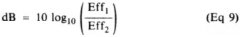
where
dB = gain, decibels
Eff1 and Eff2 = efficiencies being compared
where
Rr = radiation resistance of the base section of a top-loaded antenna at ¼-λ resonance
H = angular height of base section
![]()
where
Zsc = input impedance of short-circuited transmission line
Z0 = characteristic impedance of line, ohms
j = the complex operator
θ = angular length of line
![]()
where
C = capacitance, pF
f = frequency, MHz
XC = capacitive reactance, ohms
![]()
where
C = capacitance, pF
d = diameter, inches
![]()
where
X = resulting reactance
XC = capacitive reactance, ohms
XL = inductive reactance, ohms
![]()
where
XC = capacitive reactance, ohms
f = frequency, MHz
C = capacitance, pF
![]()
where
L = inductance, µH
XL = inductive reactance, ohms
f = frequency, MHz
(Eq 17)![]()
where
RLoop = resistance at θ transferred to current loop
Rθ = resistance at θ from current loop
θ = angular distance between resistance to be transferred and current loop
Notes
- [EDITOR'S NOTE: As Fig 2 shows, with equal power applied, more current flows at the base in the shorter, base-loaded element than in the full-size, ¼-λ element. Intuitively, it may then seem that this higher base current might yield a field-strength increase (gain) to offset some of the resistive losses, and therefore the author's figure of "8 dB down" may appear to require modification. However, not only the current amplitude, but also the current distribution in the conductor (as indicated in Fig 2) is a factor in determining far-field signal strength. The 8-dB difference can be verified with antenna analysis programs using method of moments calculations, such as NEC, MININEC, and MN. Other antenna configurations evaluated in this article can be similarly verified.]
- B. Edward, "Radial Systems for Ground-Mounted Vertical Antennas," QST, Jun 1985, pp 28-30.
- Adapted from G. H. Brown's thesis, "A Theoretical and Experimental Investigation of the Resistances of Radio Transmitting Antennas," Univ of Wisconsin, 1933, citing van der Pol and R. Bechmann, Jahrbuch O. Drahtl Telegr, 13. 217, 1918.
- From B. Byron (W7DHD), "Short Vertical Antennas for the Low Bands," Ham Radio; Part 1, May 1983, pp 36-40, and Part 2, Jun 1983, pp 17-20.
W7XC, Charles J. Michaels.