The off-center-fed dipole revisited: a broadband, multiband antenna
The search for a simple broadband, multiband antenna with acceptable SWR over the entire 80/75-meter band continued with the publication of the article by Witt, AI1H, in April 1989 QST. This inspired author Belrose, VE2CV, to reopen his files on the "Windom antenna," or, more properly, the off-center-fed dipole. Particularly since the opening of the 10, 18 and 24-MHz bands, this time-honored, somewhat controversial antenna is attracting a revival in interest and usage because of its multiband characteristics. Thus, the off-center-fed dipole deserves an update. Certainly, most North American radio amateurs have not heard about the German version of this antenna.
Even though it is one of the simplest antennas, the drooping dipole (a dipole with drooping ends, popularly referred to as an inverted V) is effective on 80 meters. For good DX performance, the apex of an 80-meter drooping-dipole antenna should be as high as possible above ground (at least 15 meters [50 feet]), because the antenna's vertical radiation angle decreases with height above ground. The arms of an 80-meter drooping dipole should not be too close to the ground (say, greater than 3 m [10 ft]). The input impedance (Ra ± jXa) of a drooping dipole depends on the operating frequency, the length of the dipole, the angle between its arms, the dipole's height above ground, and - particularly the resistive component - on the conductivity of the earth beneath the antenna. The included angle between the arms of an 80-meter drooping dipole should be about 127 °, since, in this configuration, the antenna's pattern is dipole-like, and its input impedance is about 500 for antenna heights typically employed by radio amateurs. The principal disadvantage of such an antenna is that its SWR bandwidth - less than 200 kHz - is too narrow to cover the 80/75-meter band.
The broadband performance of an antenna can be improved through the use of a matching network at the feed point. This network can comprise discrete components (see Hall,(1) Hayward,(2) Bloom,(3) Hately,(4) and Li, et al(5)); or transmission-line stubs (Snyder,(6) Hansen,(7) and Witt,(8)). Authors Li, et al give a microcomputer program for the design of LCR networks for broadband matching.
Another way to improve broadband performance is to use two dipoles fed in parallel: one dimensioned for the middle of the lower half of the band, and the other for the middle of the upper half of the band. The drooping-dipole configuration is ideal for this arrangement, since the ends of the two dipoles can be fanned (for angular separation) in either the vertical or horizontal plane. An alternative is to use an off-center-fed dipole, which, in addition to broadbandedness, has multiband performance characteristics. This article is concerned with such an antenna.
The "Windom antenna" and single-wire feed
The original Windom antenna (devised in 1928-29), named after Loren Windom, W8GZ, the amateur who wrote a comprehensive article about it,(9) employed single-wire feed at a point of 1/6 to somewhat over 1/7 of the antenna length from the center (see Fig 1A). Windom reported on a detailed experimental study by colleagues John Byrne, W8DKZ, Edward Brooke, W2QZ, Jack Ryder, W8DKJ, and Prof W. L. Everitt of the Ohio State University Dept of Electrical Engineering. They found that if ammeters were placed on the antenna, with the single-wire feeder at the position just described, the current distribution on the dipole was sinusoidal and symmetrical, with no discontinuity in the vicinity of the feed point, and no standing wave on the feeder. Clearly, the feeder was terminated in its characteristic impedance.

Fig 1 - Two versions of the off-center-fed dipole. At A, the original "Windom antenna" - actually a Hertz (½ λ) element excited via a single-wire feeder; at B, a dipole off-center-fed via balanced line. The single-wire-fed version dates from the late 1920s; the balanced-line-fed version (sans balun) dates from the 1940s, and the balanced-line-and-balun version appeared in ARRL publications beginning in the late 1950s.
This article did not discuss pattern, and it was many years before the computational tools for predicting pattern were available. Parfitt and Griffin(10) have recently analyzed the single-wire-fed dipole (the Windom antenna), and their results show, as anticipated, that radiation from the feed wire does modify the antenna pattern, primarily at low elevation angles with the horizon. The feed line for their modeled antenna was vertical.(11) The pattern was basically dipole-like, with a squint away from the broadside. Current on a wire, whether uniform (a traveling wave) or sinusoidal (a standing wave) leads to radiation, unless the radiation that results from this feed-wire current is canceled by an equal-amplitude, out-of-phase current on an adjacent parallel wire (as in a balanced transmission line). For the Windom antenna, feeder radiation could be significant, depending on the arrangement and the length of the transmission line.
| Fig 1B Version | 13.5 m (44.29 ft) | 27.94 m (91.67 ft) |
| cq-DL double-dipole version | 13.8 m (45.28 ft) | 27.7 m (90.88 ft) |
| 4.69 m (15.39 ft) | 9.38 m (30.77 ft) | |
| cq-DL double-sized, double-dipole version | 25.88 m (84.91 h) | 51.77 m (169.85 ft) |
| 4.69 m (15.39 ft) | 9.38 m (30.77 ft) | |
| Author's double-dipole version, (balanced coaxial-line feed, Fig 4) | 23.3 m (76.44 ft) | 48.2 m (158.13 ft) |
| 6.78 m (22.24 ft) | 13.58 m (44.55 ft) |
The Windom antenna was widely used during the 1930s and into the 1940s. For example, in author Belrose's experience, the British Columbia Forest Service were using the single-wire, off-center-fed dipole in the mid-1940s. It was a simple antenna that was easy to tune and match with the π network employed in the output circuit of their transmitter.
Center-fed versus off-center-fed dipoles
A center-fed dipole is a resonant antenna at its fundamental frequency* (f0) and at 3f0, 5f0, 7f0 and so on, whereas an off-center-fed dipole is resonant at f0, 2f0, 4f0, 8f0, and its bandwidth (apparently) is greater. As a low-band, multiband antenna, this off-center-fed dipole has advantages over the center-fed dipole, but a disadvantage (or advantage, depending on the antenna configuration and one's point of view) is that feeder radiation can contribute to the antenna's resultant radiation pattern. The use of a current balun minimizes feeder radiation. -VE2CV and VE3KLO
*The frequency at which it is 1/2λ long.
The off-center-fed dipole and balanced transmission line
A later version (1940s) of an off-centerfed dipole (miscalled Windom) employed 300-Ω ribbon feed at a point 1/3 of the antenna length from one end (see Fig 1B). Such an arrangement was the first antenna used by author Betrose for operation on the 80, 40 and 20-meter bands in the 1940s. Scholle, DJ7SH, and Steins, DLIBBC, have more recently modified this antenna, devising a double-dipole version that provides a good match to 50-Ω line on all Amateur Radio bands from 3.5 through 28 MHz.(12) [See the Appendix for translations of this article and that cited in Note 13-Ed.] Note that their double-dipole version provides a good impedance match to coax on the 21-MHz band, which the single-dipole 80-meter antenna did not. A double-size version provides 1.8-MHz coverage as well.(13)
Scholle and Steins added a shorter offcenter-fed dipole in parallel with the longer element, and employed a 50-Ω feed coaxial cable with a 300- to 50-Ω (6:1) balun located at the feed point. Table 1 summarizes information available on the element lengths for single and double off-center-fed dipoles. Since the dipole must be resonant on harmonic frequencies, its length must be somewhat longer than optimum for the 75-meter band, as noted by Scholle and Steins. It is apparent from their SWR curves that the resonant frequency of their antenna is less than 3.5 MHz.
In the arrangement employed by Scholle and Steins, the longer elements were horizontal and the shorter elements sloped (the included angle between the arms of which was ΛA = 100°). The authors' version was a drooping-dipole configuration (Λ ≈ 127°), with the angle between the arms of the two dipoles approximately 45°. This antenna was fed with two 15-meter (50-foot) lengths of RG-62A (foam dielectric) coaxial cable configured as a balanced transmission line.(14)
We fabricated a single off-center-fed dipole (dimensionally identical with the longer element of the Scholle and Steins "double dipole") and used it as a Field Day antenna (in 1985) for 75/80 m. The stimulus for this, and for carrying out a detailed study, was a search for a simple all-band antenna conducted for the Canadian National Institute for the Blind.(15) We experimented with 4:1 and 6:1 baluns, primarily because 4:1 baluns are easier to come by (more on baluns later). The antenna was operated in a drooping-dipole configuration (Λ = 127 °), with the apex (which, in our case, was the feed point) at about 12 meters (40 feet). (In retrospect, we should have positioned the center of the antenna at apex height, since in this configuration the current maximum on the antenna [for 80-meter operation] would be at maximum height.) Extensive impedance and SWR measurements were made. To facilitate this, we employed a low-loss (foam-dielectric) coaxial feeder consisting of a 32.3-meter (106-foot) length of Belden 8214 (velocity factor, 0.8.) This feeder was ½ λ long at 3.5 MHz, 1 λ at 7 MHz, and so on. High-quality commercial baluns (made by Antenna Engineering, Australia(16)) were used between the feed line and the antenna.
Fig 2 shows our SWR measurements for the 80/75-meter band. With the 6:1 balun in line, the 2:1 SWR bandwidth was 3.47 to 3.93 MHz-broadbanded, indeed. The SWR was even lower on 40 and 20 meters, and less than 2:1 for the lower half of the 10-meter band; see Fig 3. Clearly, these bandwidths are not in accord with simple theory.(17) Fifteen-meter data are not shown because this single off-center-fed dipole was not resonant on the 15-meter band.
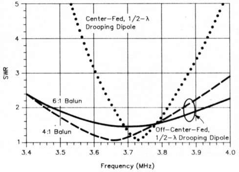
Fig 2-SWR v frequency for a single off-centerfed dipole employing different baluns (4:1 and 6:1) at the feed point, compared with a center-fed ½-λ dipole. Both antennas were operated in a drooping-dipole configuration.
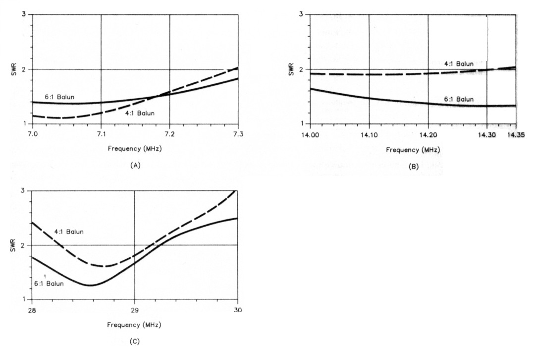
Fig 3 - SWR v frequency for the off-center-fed dipole of Fig 2 at 40, 20 and 10 meters.
The 4:1 balun provided somewhat sharper resonances and lower SWR at resonance in the 80/75- and 40-meter bands, but a low SWR was not obtainable in the 20-meter band. The measured impedance at resonance in the 80/75-meter band with this balun was exactly 50 Ω, hence the antenna's effective feed-point impedance was 200 Ω. This explains why the minimum SWR with the 6:1 balun was 1.5:1; the 6:1 balun, however, seems to be a better compromise if operation on other bands is wanted.
As noted, we employed high-quality commercial baluns (from the AEA Model 250 series). Radio amateurs have several alternatives in this connection; these include using a 4:1 balun and 75-Ω coax; or purchasing or winding your own 6:1 balun (see Orr, W6SAI(18)) and using 50-Ω coax.
Aside from impedance matching, however, there are other factors to consider in feeding an off-center-fed dipole and selecting a balun for this service. Next, we address some of these aspects.
Balun and feeder considerations
In the autumn of 1989, we decided to have another look at off-center-fed dipoles. Because of the multiple-resonant-frequency response of the double off-center-fed dipole, we decided to explore the potential of this antenna system for broadband frequency coverage. If used with a suitable antenna-system tuning unit (ASTU), a double off-center-fed-dipole system could perhaps be used on any frequency from 1.8 to 30 MHz. Since conventional baluns do not perform satisfactorily into reactive loads, we decided to eliminate the balun, at least insofar as the antenna and its feeder were concerned. We fed our antenna with a balanced 190-Ω transmission line consisting of two 15-meter (50-foot) lengths of RG-62A (foam-dielectric) coaxial cable as shown in Fig 4 and described in the work cited in Note 15. Teflon® -dielectric cable would have been preferable because of Teflon's superior insulating characteristics, but 95Ω, Teflon-dielectric coax is unavailable.
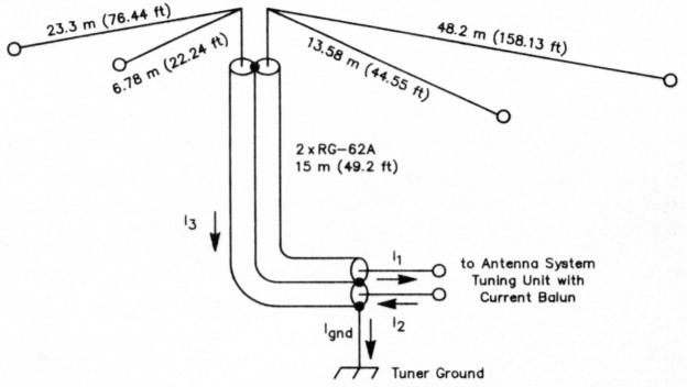
Fig 4 - A double-dipole, off-center-fed antenna with a balanced coaxial-line feeder. The longer dipole is dimensioned to ½-λ at 2 MHz; the shorter dipole is dimensioned to minimize the system impedance at 7.6 MHz. See text.
We started out with a single dipole element dimensioned to ½ λ at 2 MHz. This antenna exhibited an antiresonant response (very high input impedance, measured at the transmitter end of the transmission line) at 7.6 MHz. Next, we installed the shorter dipole and dimensioned it to minimize the system's impedance at 7.6 MHz. Fig 5 shows the system's impedance v frequency. Except for a narrow band of frequencies near 6 MHz, the input resistance fell in the range of 20 to 400 Ω; and the input reactance fell in the range +j100 to - j200 Ω. This double off-center-fed dipole system is rather easily tuned and matched, since its reactance is low.
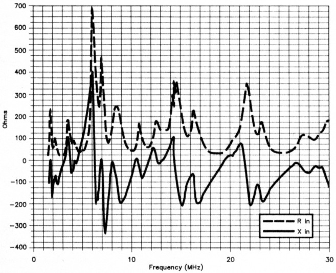
Fig 5 - Impedance (input resistance [R in] and input reactance [X in]) v frequency for the antenna shown in Fig 4.
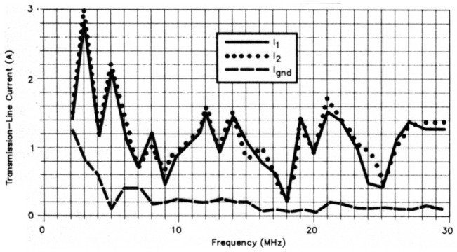
Fig 6 - Transmission-line currents (peak values for 100-W transmitter output power) for the antenna shown in Fig 4, tuned by means of an unbalanced T network and a ferrite-beadchoke (W2DU) current balun.
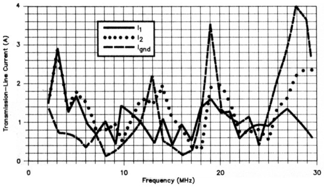
Fig 7 - Transmission-line currents (peak values for 100-W transmitter output power) for the Fig 4 antenna, tuned by VE2CV's balanced tuner, which employed a voltage balun.
For an antenna that is asymmetrical with respect to its feeder - such as an off-centerfed dipole - a current balun must be used, since this type of balun forces almost equal currents into each conductor of the balanced line. This is necessary if transmission-line radiation is to be minimized. If these currents are exactly equal, there will be no difference in current flowing in the ground lead (Ignd), which connects the braids of the coax to the tuner ground. Any current on this lead is then due to radiation-coupled current (I3) induced on the outside surface of the coaxial shield. Clearly, we want this current to be small (to minimize radiation from the transmission line), and indeed it is small except at frequencies below 3 MHz (see Fig 6). (Our antenna was suspended from a bracket at the 12-meter [40-foot] level on a 21-meter [70-foot] aluminum-lattice mast. In the final analysis, reradiation by this mast should be considered because current may have been induced on the mast surface).
Off-center-fed dipoles for the amateur radio experimenter
The off-center-fed dipole used by author Belrose in the 1940s was fed with 300-Ω twin lead via a balanced ASTU that was link coupled to a balanced (push-pull) power amplifier. There was no concern about balun losses and what type of balun to use because the system contained no balun.(20)
The authors' double-dipole, off-centerfed antenna employed a balanced coaxial feed line. This antenna was attractive for the authors because it could be used throughout the HF range if fed via a suitable matching network. If you decide to fabricate and try an off-center-fed dipole system, we suggested that you dimension it in accord with the Scholle and Steins versions, which are optimized for the amateur bands. Furthermore, we suggest that you feed such an antenna with a balanced transmission line. We have used dual RG-62A cables to make a balanced 190-Ω line, but one could use paralleled RG-63 (125Ω) coaxial cable, which would make a balanced transmission line more in accord (Z0 ≈ 250 Ω) with the traditional 300-Ω-twin-lead feeder. In such a system, the balun, and the ASTU (if required), can be in the shack to allow experimentation in achieving balanced current feed and reducing losses in the balun. Whatever method you use, feed your off-center-fed antenna via a current balun.
A shield-choke current balun can be constructed by slipping ferrite beads (-43 or -73 material) over a length of coaxial cable. (Depending on the beads obtainable and the diameter of the cable you use, you may need to remove the cable's outer jacket and install the beads directly around the shield.) As described in the work cited at Note 19, Walt Maxwell, W2DU, used 50 beads of no. 73 ferrite (Amidon no. FB-73-240l, Palomar FB-24-73 or equiv) on a piece of Teflon-dielectric cable to make a practical, low-loss, 1.8-to-30-MHz balun about 12 inches long.(21) Such a balun, however, is a 1:1 transformer - not very useful for the present application, where impedance transformation is also required. A 4:1 balun of similar type (see Note 20) can be constructed by using two equal lengths of RG-62 (9541) coaxial cable, each fitted with ferrite beads. The inputs to these two coaxial-cable baluns are connected in parallel, and the outputs in series (see Fig 8). This makes a center-tapped 4:1 balun.
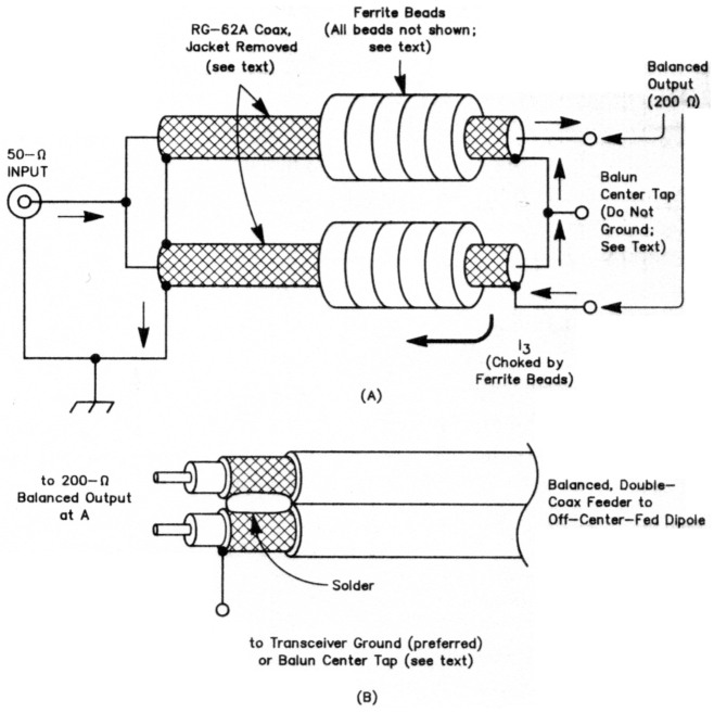
Fig 8 - At A, a 4:1, ferrite-bead current balun; at B, connections to the balun end of the dual-coax balanced feed line.
Our antenna feeder has a center tap: the braid of the balanced coaxial transmission line. The braids of the transmission-line cables can be grounded to the center tap at the transmitter side of the balun, or to the ASTU (or transceiver) ground. Connecting them to the transceiver ground is the better arrangement because the transmission-line currents are better balanced, and the braid current is less. (For the braid-to-ASTU-ground connection, the braid current is measured in the wire connection to the balun center tap; in the braid-to-transceiver-ground case, the braid current is measured in the connection to the equipment ground.)
Performance
Our single-element Field Day antenna worked well for us; as previously noted, however, we employed it only on 80/75 meters. On this band, it is essentially a ½-λ dipole with unconventional feed. At higher frequencies, the pattern develops lobes because the dipole acts as a long-wire antenna. Provided that this directivity coincides with directions of interest, the off-center-fed dipole is a good, simple broadband/multiband antenna.
The authors' 1989 (double-dipole) version, while not designed specifically for Amateur Radio communication, has been used on various amateur bands (during the winter of 1989-90). It works, but how well? We checked into various nets on 75 and 40 meters. On 75, for instance, we checked into the ONTARS (Ontario Amateur Radio Service) net, and the Newfoundland Phone Net (1730 EST), two regions at quite different distances from the Ottawa area. The reports received were comparable with those given to other stations by net control. On the 160-meter band, we found that we could work stations we could hear, provided that they were running comparable power (100 W) and their local noise levels were reasonable. We have not yet determined the antenna's gain and pattern.
Acknowledgment
The authors work at the Communications Research Centre, Shirleys Bay, Ontario. The measurements for the double-dipole off-center-fed dipole system were made at the Laboratory as part of a study of broadband HF wire antennas.
Notes
- J. Hall, "The Search for a Simple, Broadband 80-Meter Dipole," QST, Apr 1983, pp 22-27.
- W. Hayward, "Limitation to Broadband Impedance Matching," Technical Correspondence, QST, Jul 1984, pp 45-47.
- A. Bloom, "Once More with the 80-Meter Broadband Dipole," Technical Correspondence, QST, Jun 1985, p 42.
- M. Hately, "Multiband Dipole and Ground Plane Antennas," Third lEE International Conference on HF Communication Systems and Techniques, Conf Series Pub 245, pp 102-106, 1985. Maurice Hately, GM3HAT, has patented his method of feeding and matching HF dipoles (UK Patent GB 2112579), and he manufactures and markets his "dipoles of delight."
- S. Li, J. Rockwell, J. Logan, and D. Tan, Microcomputer Tools for Communications (610 Washington St, Dedham, MA 02026: Artech House, 1983), Ch 14: Broadband Matching.
- R. Snyder, "The Snyder Antenna," rf design, Sep/Oct 1984, pp 49-51.
- R. Hansen, "Evaluation of the Snyder Dipole," IEEE Trans on Antennas and Propagation, AP-35 (No. 2), pp 207-210, Feb 1987.
- F. Witt, "The Coaxial Resonator Match and the Broadband Dipole," QST, Apr 1989, pp 22-27.
- L. Windom, "Notes on Ethereal Adornments," QST, Sep 1929, pp 19-22, 84.
- A. Parfitt and D. Griffin, "Analysis of the singlewire-fed dipole antenna," IEEE AP-S International Symposium, Vol Ill (IEEE cat no CH-2654-2/89, Library of Congress no 89-84327, Jun 1989, pp 1344-1347.
- "Such an arrangement is an extreme case because the feeder is perpendicular to the ground - a configuration probably atypical of single-wire feed in Amateur Radio installations, and one that affords practically zero cancellation between feeder and ground currents. At the other extreme, one of the amateur systems described in Windom's "Notes on Ethereal Adornments" (see Note 9) employed a 1200-foot-long (365.8-m) feed wire that likely more nearly approached parallelism with the ground. Clearly, "modeling a Windom" is a fuzzy procedure. - Ed.
- H. Scholle and R. Steins, "Eine Doppel-Windom Antenne für Acht Bander," cq-DL, Sep 1983, p 427.
- H. Scholle, "Eine Doppel-Windom Antenne für Neun Bander," cq-DL, Jul 1984, pp 332-333.
- J. Betrose, "Tuning and Constructing Balanced Lines," Technical Correspondence, QST, May 1981, p 43.
- J. Swell, VE3KF, and W. Loucks, VE3AR, private communications. Apr 1985.
- Antenna Engineering, Australia Pty Ltd, PO Box 191, Croydon, Victoria 3136, Australia.
- W. Wrigley, "Impedance Characteristics of Harmonic Antennas, QST, Feb 1954, pp 10-14.
- W. Orr, Ham Radio Techniques, ham radio, Jan 1983, pp 68-69.
- EM. Maxwell, "Some Aspects of the Balun Problem." QST, Mar 1983, pp 38-40.
- J. Belrose, "The Balun Saga Continued," QST, in preparation.
- As a less-costly alternative. 10 ≈ 1-inch-long mix-77 beads - with an inner diameter to pass the coax used - may serve as a substitute. (The authors do not have experience with beads of this material, however.) Consult your ferrite-bead supplier on the availability of beads of this type. - Ed.
Appendix
A Double Windom Antenna for Eight or Nine Bands
This work, which originally appeared as two articles in cq-DL, was translated from the German by Dr. George Elliott Tucker, WA5NV1.
Part 1: A double windom antenna for eight bands
By Hubert Scholle, DJ7SH, and Rolf Steins, DL1BBC
The asymmetrical dipole antenna developed and described by Windom (W8GZ) in 1929 has been used by many amateurs for many years as the FD4. This has also been the case in Germany.
We discovered in an older periodical (QRV) the explanation by F. Spillner (DJ2KY) that this antenna, with the addition of a small one-band Windom for 15 m, can be used as a five-band Windom. After the installation of the additional elements, this antenna worked very well for two years at DL1BBC.
With the opening of new bands (10, 18 and 24 MHz), the thought occurred to try out a new extension of the FD4 to eight bands (3.5 to 29.7 MHz).
What worked for 21 MHz must also be possible for 10 MHz.
So we took off the 21-MHz extension to my antenna and hung two elements of 4.69 and 9.38 in (15.39 and 30.77 ft), respectively, on the FD4 and stretched these downwards from insulators as an inverted V (Fig A).
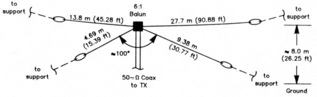
Fig A - Double Windom.
To calculate the length we used the formula:
L/2 = 142.5 ÷ f (Eq A)
Whatever would work for 30 m should also work on 15 m.
As suspected, it worked.
As a by-product, it turned out in the measurements that this double Windom resonated just as well on 18 MHz and 24 MHz. So our eight-band Windom came into being with really simple means.
Construction
Thanks to our neighbors, we were able to extend the basic antenna (FD4) to its full length.
At DL1BBC it was installed about 6.9 m (22.63 ft) above the ground, rising to about 8 m (26.25 ft) at each support point. At DJ7SH it hung about 5 m (16.4 ft) above the ground and partly ran over a garage roof. Both extension legs were stretched downwards as an inverted V with an angle of about 100°. Changing this angle allows the whole antenna to be easily tuned during final adjustments.
After construction, the first measurements showed that because of the length of the 30-m elements, the 80, 40 and 20-m bands each had a resonance point that was shifted towards the low end of the band. This effect was eliminated by lengthening slightly the 30-m section, so the resonance points fell more in the middle of the bands.
With this adjustment, the resonance point on 30m shifted slightly towards the end of the band, but this can be tolerated.
With all measurements of the Windom, it was very clear that how the feed line ran played a decisive role.
According to our results, it must be stressed that the feed line must run first vertically downwards from the feed point to the ground and only then to the shack, as otherwise the entire antenna may be detuned. This is especially the case when the height of the antenna is under 10 m (32.8 ft). The 50-ohm-coax feed at DL1BBC was pulled through an old garden hose and then buried under the lawn.
The lower antenna height at DJ7SH had the result that, with the first construction attempt, the precalculated length of the 30-m elements was exactly right. The antenna delivered on all eight bands at the first go.
As can be seen from the SWR charts (Fig B), at DL1BBC the match on 40 m turned out somewhat less favorable. However, this was immediately fixed by changing the antenna height slightly. At DJ7SH, no resonance curve ran above 1.5:1, which was the goal since neither station uses an antenna tuner.
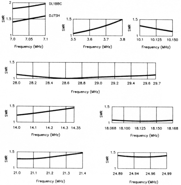
Fig B - SWR curves for the eight-band double Windom [These curves do not cover all US amateur frequencies because allocations in the FRG differ from those In the US - Ed.]
Performance
First contacts were made with both antennas. These showed that the antennas had a good degree of performance for a long wire. Especially the downwards sloping extension elements have a clear advantage over the horizontal basic antenna for DX.
With the first try on 30 m, many contacts were made with the US (East and West coasts), with signal reports between S6 and S7 while running 100W.
At present, we cannot make a concrete statement about contacts within Europe.
This article makes no scientific claims, but intends to stimulate the long-wire enthusiast, and especially the friends of CW.
Part 2: Adding Another Band
Because the response was unexpectedly great to the publication of the above in cq-DL, we went to work again on an extension, as it was worthwhile to add 160 m.
With a half wavelength at 1.835 MHz, we calculated the basic length of the antenna to be 77.65 m (254.75 ft). We tapped the antenna at 25.88 m (84.9 ft) from one end and fed it with 50-ohm coax through a 6:1 balun. The basic antenna of this length was installed horizontally as a reclining L at DL1BBC. The additional elements, with lengths of 4.69 and 9.38 m (15.39 and 30.77 ft), were attached at the balun. This additional Windom for 10 and 21 MHz was again stretched downwards as an inverted V with an angle of about 100°. Here the additional Windom was mounted so that its elements were not extended in the same direction as those of the reclining L, which gave sufficient decoupling (Figs C and D).
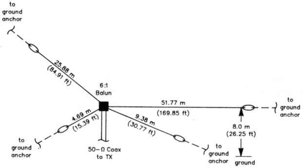
Fig C - A double Windom antenna for nine bands.
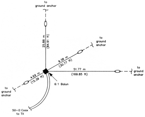
Fig D - Top view of the nine-band double Windom. [The elements are positioned to reduce coupling between the antenna's two ott-center-fed dipoles. - Ed.]
For the feed, the Fritzel company made available for testing a new 6:1 balun, series 83, which can also handle high power. The SWR charts (Fig E) were obtained with the wire lengths given in the preceding paragraph. In case builders experience slight resonance shifts, these can be balanced out by lengthening or shortening the additional Windom.
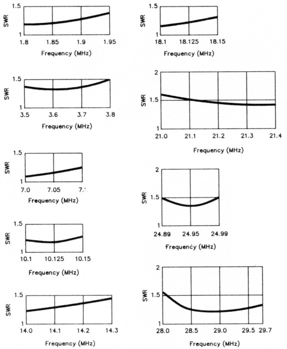
Fig E - SWR curves for the nine-band double Windom.
Performance
First contacts were made with the antenna installed at DL1BBC. Here it was once again shown that the antenna has a good degree of performance for a long wire, especially for 1.8 and 3.6 MHz within Europe. The additional Windom again had the degree of performance described in the first part of this article.
The authors welcome questions and exchange of information. (When writing, please include return postage.)
VE2CV, John Belrose and VE3KLO, Peter Boubane.