A Laser-Communications Primer 2
Part 1 of this article appeared in QST, Sep 1990, pp 19-24.
Anxious to start DXing with your own laser system? Here's how!
For the amateur interested in experimenting with optical communications, there has never been a more opportune time to enter the field. Lasers, optical-fiber assemblies and optical-communications technology in general have advanced to the point where the hardware required to build a laser-communications system is not only readily available, but is also affordable for the average amateur.
This article builds on last month's introduction to laser light, optics, laser sources and detectors.(21) I'll describe the basics of light propagation and detail practical and affordable laser-based communications systems you can build, such as the modified laser-tag transceiver shown in Fig 8.
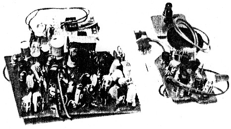
Fig 8 - A complete optical communications system, based on a modified IR-laser-tag game. The receiver circuit board (left) has been modified for low-level visible-light work through the addition of a visible-range photodiode and op-amp-based preamplifier (on the pert board to the rear of the main receiver board). The smaller transmitter board (right) has been modified for visible-light operation by substituting a pair of high-output red LEDs for the original IR set (on the small board to the rear of the main transmitter board). The transmitter is useful for testing the receiver and associated optics, because it eliminates the need to work with high-power laser light at close range. (NU1N photo)
Light Propagation
To fully exploit the potential of free-space laser communications, you need to understand how light propagates from a source to a receiver. In an excellent QST article,(22) Bob Atkins, KAIGT, pointed out that laser-communications range is not only a function of output power and receiving-optics area, but is also affected by atmospheric transmissivity, receiving-optics quality, optical-detector sensitivity and laser-beam divergence. As one would expect, the more sensitive the receiver and the greater the output power, the greater the maximum theoretical range. As Atkins also reveals, the best approach to designing optical-communications systems is to develop the most sensitive detector you can, because large receiving lenses, like high-power lasers, are expensive and difficult to manage.
As in Amateur Radio RF communications, despite our efforts at developing of acquiring the best transmitter, receiver and antenna system possible, nature sometimes doesn't cooperate. Just as we use our understanding of the interplay between the sunspot cycle and the state of the ionosphere to plan our MF/HF activities, by understanding how light propagates through the atmosphere, we can better select laser-communications sites and times.
Transmissivity of receiving optics is determined by the quality of the construction materials used, and the propagation of light through the atmosphere is affected by moisture and dust content, as well as turbulence. Rain, snow and other precipitation can absorb, refract and reflect light, significantly reducing communications range.
Even relatively clear, calm air can diminish the intensity of a laser beam via scattering. Scattering is caused by the irregular arrangement of the atoms that constitute air. If a photon from a laser beam strikes an atom, the atom gives off another photon, at the same frequency, but in a different direction.(23) That is, the photon will be diverted away from the desired receiving site. Because scattering is proportional to the fourth power of the frequency, blue light - about twice the frequency of red light - is scattered sixteen tunes as much as red light. (This scattering accounts for the sky's blue color on clear days.) Rain and water vapor also scatter light, and smaller droplets affect blue light more than red light. That is, as droplets increase in size,blue light disappears first, enhancing the reds. Luckily for both IR- and HeNe-laser enthusiasts, the IR and red regions of the spectrum are relatively unaffected by atmospheric scattering.
Although it's not n factor in short-range communications, light bending is a con sideration in longer-range (over 5 miles) laser work. Light, whether from a laser or the sun, travels faster through less-dense hot air than denser cool air. In much the same way that the refractive differences in optical fiber effectively constrain light to travel within the fiber core, temperature differences in the atmosphere can cause light to travel in curved paths.(24) For example, the optical illusion of distant water on a hot road - a mirage - is simply sky light reflected on the road. Light from the sky, originally headed for the road, bends upward toward the observer.
Light bending is especially important when working with IR laser systems. Because an IR beam may be bent to a greater or lesser extent than visible light, simply aiming your IR laser at the receiver site may not be sufficient. Don't immediately suspect component failure if you can't quickly make contact with a distant station; try aiming your laser a bit high or low to take advantage of bending.
Laser Power Supplies
The power required by a low-power semiconductor laser can be provided by any regulated supply capable of driving a common LED (for example, a battery with an appropriate series resistor). At the other extreme, HeNe lasers, as well as some optical detectors, require a supply capable of delivering 2 to 3 kV dc at several milliamperes. Fortunately, a number of power-supply alternatives are available, including surplus high-voltage "bricks," kits and new commercial supplies.
My first HeNe-laser power supply, which survived for about 5 years, was based on a portable black-and-white TV set. I tapped the HV directly from the picture-tube anode connection - with the tube still attached. The tube's capacitance provided the needed filtering. Obviously, this approach requires the usual attention to HV-shock precautions.
My current HeNe laser supply was described in a recent Radio-Electronics article.(25) It is also available as a complete kit (from General Science and Engineering, PO Box 447, Rochester, NY 14603, tel 716-338-7001) for about $40. This switching supply uses a 555 timer chip running at 16 kHz. I found the kit lacking in a few areas, but it is a good basis upon which to build. After substituting no. 12 wire for the no. 22 wire supplied for the 12-V dc input, I had little trouble using the supply to power my 5-mW HeNe laser tube. I solved a corona-discharge problem by covering all exposed HV connections with a generous amount of silicone sealant. Sudden HV discharges are fatal to 555s - I went through three ICs before stabilizing the supply. If you plan to purchase this kit, you might want to pick up a few extra 555s.
As with all HeNe laser systems, you'll need to insert a ballast resistor between the HV power supply and the laser tube. Unless you have the tube's data sheet, you will have to use a trial-and-error approach to determine the needed resistance. The kit described above includes a number of 2-W carbon resistors for use as ballast. I found that two 100-kit resistors in parallel were optimum for my 5-mW tube.
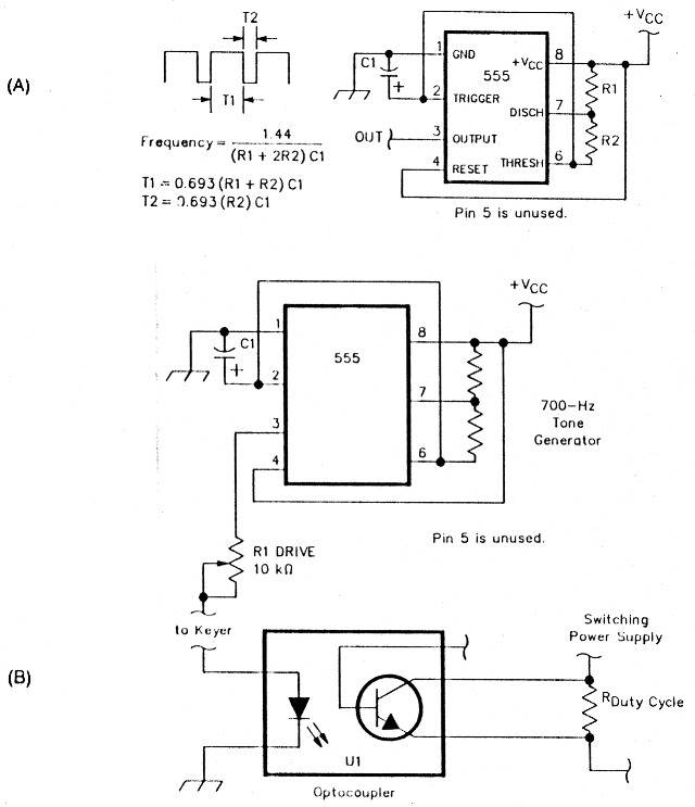
Fig 9 - Configured at A as an audio square-wave generator, the popular 555's output-waveform characteristics are defined by only three external components. This circuit (or a derivative) is commonly used to provide the clock for switching power supplies. A good way to tone-modulate a HeNe laser beam is to modulate the HV power supply's duty cycle, as shown at B. In this example, a 555 configured as a tone generator modulates the power supply at 700 Hz. Adjust R1 for optimum drive. A common optocoupler (U1) provides an added layer of safety, isolating the straight key or keyer from potentially damaging voltages in the HV-supply circuit.
My HV switching power supply has a potentiometer for adjusting the pulse width of a 555-generated square wave (Fig 9A shows how the 555 can be used as a pulse generator). This square wave drives a high-current switching transistor connected in series with the switching-transformer primary, which regulates the current flow through the laser tube. In my system, I use another 555 to drive the LED in an optocoupler (TIL111, Radio Shacks no. 276-1654) at 7(X) Hz (see Fig 9B).
The phototransistor's collector and emitter are connected across a 1-kit resistor in series with the pulse-width potentiometer. Decreasing the effective resistance of the series resistor decreases the supply's pulse width, so increasing drive to the optocoupler LED decreases power-supply output. In configuring the system, I increase the 700-Hz drive to the optocoupler I.EI) until the laser just begins to sputter from lack of current and then back off the drive. This setting represents the 15% modulation limit.
If your laser supply is encapsulated - providing access only to the 12-V dc input and 2- to 4-kV output - you'll have to resort to other means of varying the HV output. I've found that modulating the I2-V dc input to these switching supplies is useless, especially in well-designed units. A simple and inexpensive approach that works for continuous tones as well as voice modulation is inserting the primary or secondary of a suitable transformer in series with the HV supply (see Fig 10). The transformer, which should have adequate primary-to-secondary isolation, and the characteristics of your particular laser tube, define exactly how much audio drive is required to realize full (150/u) modulation. 1 use the primary of an old 6.3-V filament transformer as the series element, driving the secondary with a simple 555 tone generator and an LM386 audio amplifier.
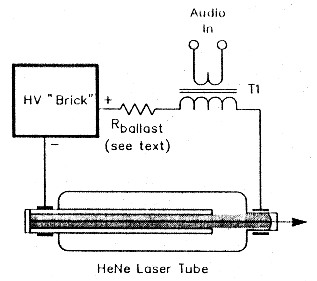
Fig 10 - Voice and tone modulation of a HeNe laser tube can be easily accomplished, even when the power supply is encapsulated. The primary or secondary of transformer T1 is inserted in series with one of the HV lines to the laser tube. An audio tone or voice signal fed into the unused primary or secondary winding causes an instantaneous change in lasertube supply voltage, varying the laser's output power accordingly.
Because most HeNe-laser power supplies are switching types, the carrier is usually modulated at the switching frequency. In my system, a simple low-pass audio filter on the receiver output easily removes the 16-kHz switching modulation, as it is relatively far removed from the normal CW and voice frequency ranges (700 and 300 to 3000 Hz, respectively).
HeNe lasers are designed to be run continuously, but semiconductor-diode lasers are generally designed for pulsed operation. As such, your diode laser system should be pulse-width modulated to realize the best communications results and diode life. You can easily pulse-width modulate a laser diode through the use of a circuit similar to that used to modulate the pulse width of a HeNe-laser switching power supply (see Fig 9B). For low-power laser-diode applications, simply substitute a laser diode for the optocoupler LED. Higher-output (more than a few milliwatts) diodes require the addition of a series switching transistor.
Optical Assemblies
Designing and constructing the optics for a laser-communications system from scratch can be an enjoyable and rewarding experience, but unless you have some experience with lenses and other optical devices, you are probably better off using a prcassembled system. As you gain experience, you can modify and adapt the system to suit your needs.
Used telescopes, of both refractor and reflector designs, make excellent, preassembled optical "antennas." Refractor telescopes, which are designed much like singlelens-reflex (SLR) telephoto camera lenses, with glass lenses at either ends of an adjustable-length tube, make excellent collimating devices. As shown in Fig 11, refractor telescopes, sometimes sold as "spotting scopes," can be used in reverse (with the laser light entering the ocular, the aperture usually placed closest to the eye) to produce a more parallel - collimated - beam.
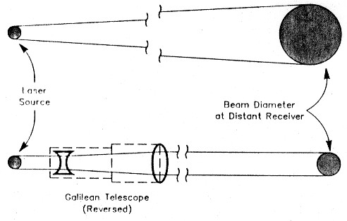
Fig 11 - Given enough distance, even the relatively parallel light from an adjusted HoNe laser light disperses to the point that the tight intensity is too small to detect, even with the best receiver system. To minimize light dispersion, and therefore increase laser-communications range, a collimating system, based on a common Galilean (spotting) telescope, can be used.
For example, a 10 x telescope or spotting scope can be used to collimate a HeNe laser beam such that, at 100 yards, the illuminated disc that would normally be 4 inches in diameter is reduced to only 0.4 inches in diameter. The result is a more intense beam at a given distance, and therefore greater possible range.
Reflector telescopes, usually more compact for a given aperture than refractor types, make use of a primary-surface curved mirror to gather light. As shown in Fig 12, many reflector (and refractor) telescopes have integrated spotting scopes designed to aid in aiming the larger telescope. These integrated units make excellent laser communications assemblies. The smaller spotting scope, which should be inverted from its normal position, can serve as the laser collimating assembly, and the larger-aperture main telescope can he used for the receiver. An added bonus to usinga telescope assembly, especially one of the better models, is the (usually) excellent support system. A good, stable tripod or other such mount is essential for long-distance work.
Laser Accessories
Just as an assortment of instruments - such as a good SWR bridge and VOM - are essential for the day-to-day operation and maintenance of an amateur RF communications system, there are a number of indispensable tools for laser-communications enthusiasts. These tools can be broadly categorized as either focusing aids or power-measurement devices.
Focusing Aids
Focusing aids, valuable in any optical system, are especially useful for IR work. Because IR light is invisible, some means of visualizing the beam must he provided,unless you want to work with a trial-anderror approach. There are two basic types of IR focusing aids: IR-detecting cards and IR-to-visible-light converters. Detector cards, designed for testing IR remote appliance controllers, are available for about $7.(26) Before use, these phosphor-coated cards must first be sensitized by exposing them to ordinary white light for about one minute, thereby allowing the phosphor to absorb energy in both the UV and visible ranges. Then, in subdued light, stimulating the phosphor by IR light causes the phosphor to release energy in the form of a pale red, orange or yellow glow. Exercise caution when you use one of these cards with high-power beams, so as not to damage the phosphors. If you must work directly with a high-power beam, expose the card to IR light for only brief periods at a time.
IR-to-visible converters, like IR-detecting cards, rely on phosphors to convert IR to visible light for tuning, focusing and aiming IR lasers. Unlike IR-detecting cards, however, these converters do not block the light path, but effectively replace the invisible IR beam with a beam of visible light. More sensitive and capable than simple IR detecting cards, IR-to-visible converters can be expensive, with prices varying as a function of sensitivity and the length of time the converter can be used before recharging. For short-duration (10-s) converters with a minimum-detectable-power rating of 8 p.W/cm2, the price for a new unit is approximately $25 from Edmund Scientific Co.(27) For a converter with a 3µW/cm2 sensitivity, you can expect to pay $200 and up (Edmund Scientific Co). On the high end, new converters that last up to 2 minutes before recharging cost from $400 to $1000.
Although not really a staple of optical-communications experimenters, night-vision systems can also be used to transform IR-laser output into visible light. However, these tend to be expensive when new ($1000 and up).
Power-Measurement Devices
Most commercial laser-power meters are designed to measure the outputs of laser devices used in audio- and video-disc players. Many, such as the Leader LPM-8000 (about $240), are calibrated for both IR-diode lasers and HeNe lasers with power ranges from 0.3 to 3.0 mW full scale. Metrologic also sells a HeNe-laser power meter with full-scale ranges of 200µW to 20 mW ($350). if you're planning to purchase a new or used laser-power meter, look for one with an acceptable frequency response, ie, 0 to 20 kHz, if you plan to use voice modulation.
If you can't locate a surplus power meter, general-purpose photographic light meters provide a less costly alternative. These devices, which are usually very compact and lightweight, typically sell for around $70.
Setting Up a Laser-Communications Station
As a firm believer in "repurposing," I suggest that the simplest, most economical way of acquiring a functional optical-communications sysegt is ,to modify the transmitter and receiver from one of the popular laser-tag games (see Fig 8). These toys, available from over a dozen manufacturers (including some Radio Shack stores), typically contain two IR-LED transmitters and two IR receivers, all for under $30.
The receivers in these systems seem designed with the CW operator in mind, since they typically come equipped with onboard, 555-based tone generators that are triggered by the receipt of a pulsed-IR light beam. By modifying one or two resistor values, you can easily adjust the length of the tone (normally a few seconds - to signal that the receiver wearer has been "tagged") to the duration of the received signal. These units have a nominal range of about 50 feet, but I have used a simple 2-inch lens system to extend that range over tenfold. The successful use of simple, low-power IR systems consisting of IR LEDs and phototransistors with small-diameter lenses, has been described in Amateur Radio literature.(28)
Fur serious communications work, you will need to replace the transmitter's IR LEDs with visible or 1R laser diodes, and perhaps add a more sensitive detector to the receiver. In the system shown in Fig 8 (taken from a $9 laser gun/target toy), I replaced the original IR phototransistor with a visible-light PN photodiode and a 741 op amp. With the addition of a 10-inch Fresnel receiving lens, I have used this receiver to consistently receive a 5-mW HeNe laser/spotting-scope transmitter from a distance of over 6 miles. (I use identical transmitter/receiver systems, with oneplaced on a hill and the other on the roof of my apartment building.)
Even if you opt to use a HeNe laser instead of upgrading the LED transmitter, it is a good idea to keep the transmitter around as a test instrument (for tuning the receiver without the potential hazards of working with higher-powered HeNe lasers). You can easily replace the original IR LED with a red LED for a light source that operates near the HeNe's operating frequency. Similarly, an IR remote TV controller can be used to test IR (and, at close range, visible-light) receivers. Upon pressing a button on the control, you should hear a short burst, followed by a series of low-frequency (<5-Hz) pops or clicks (if the button is held down), corresponding to the control's digitally encoded signals.
If you already own a laser-light source and only need a receiver to complete your communications system, you should consider using a self-contained IR receiver, such us the one marketed by Sunset tlnlimited.(29) This $15 device, designed for testing remote-control units, contains a built-in audio amplifier and speaker. With the addition of a 2- or 4-inch lens from a hand magnifier, this unit makes a good IR-laser receiver. Adding an earphone jack is a simple matter, as is replacing the IR phototransistor with a visible-range photodiode for visible-light operation.
If you like to build, consider the simple receiver schematic shown in Fig 13. Nothing more than a high-gain audio amplifier, this circuit makes use of a corn-mon 741 op amp (Ul) and an LM386 audio amplifier (U2). Powered by a 9-V battery, the amplifier can be used with a variety of optical detectors, including solar cells, photoresistors, photodiodes, LEDs and phototransistors. The audio-amplifier stage from a portable radio could also he used.
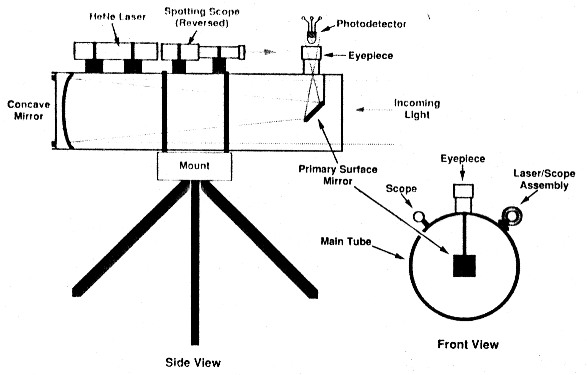
Fig 12 - Reflecting telescopes make excellent laser-communications platforms. By mounting the HeNe laser on the main telescope tube, you can avoid the hassles of independently aiming the transmitter and receiver systems. Don't use the telescope's spotting scope for the transmitter-beam collimator; use it to aim the transmitter/receiver assembly.
Once you have a good, basic laser transmitter and receiver, the next step is to mount them, with their accompanying optics, so that they are both portable and easy to use. As mentioned earlier, a high-quality reflector telescope for receive, coupled with a spotting scope mounted on the main telescope tube, makes for an excellent optical-communications-system platform (see Fig 12). A lightweight and inexpensive transmitter/receiver platform can also be constructed from ordinary PVC tubing and an inexpensive spotting scope (such as the models sold for BB and pellet rifles).
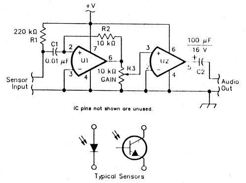
Fig 13 - A simple laser receiver. U1, a 741 op amp, amplifies the output of a photodiode, phototransistor or other optical detector, and drives U2, an LM386 audio amplifier. Resistors are 1/4 W, and capacitors should have a rating of 16 V or greater. + V is supplied by a 9-V battery.
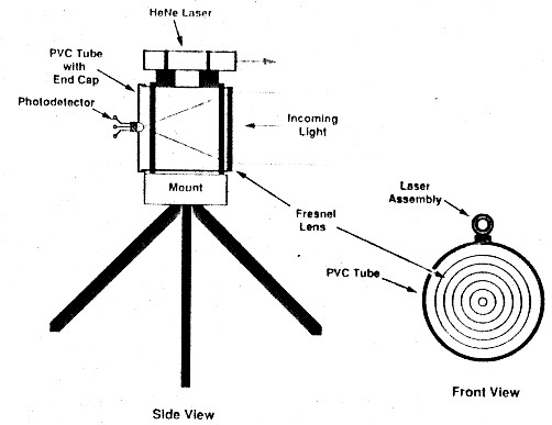
Fig 14 - Plans for an inexpensive, home-brew optical-communications platform, based on a HeNe-laser transmitter and a Fresnel-lens-based receiving system. Drill a small hole in the bottom of the main PVC tube to allow moisture to escape.
As shown in Fig 14, a lightweight Fresnel lens can be cemented (with silicone sealant) to the front of a PVC tube with a diameter appropriate for the Fresnel lens. Cut the PVC tube such that its length is slightly longer than the Fresnel lens' focal length, and place a PVC cap on the end opposite the lens. Drill a hole in the center of the end cap to accommodate the optical detector assembly, making certain to allow for slight adjustments in the optical detector's position and orientation. Surplus telescope hardware, such as the ocular drive meganism from a reflector or refractor telescope, can make a great optical-detector mount.
Lasers and You: Peaceful Coexistence Depends on Safety
Novice laser experimenters should not attempt to work with high-power visible or IR lasers of any type, but should instead start with a low-power (1- or 2-mW), visible-light laser system. Only after you understand the physics and biological hazards associated with a relatively safe system should you consider moving up to more powerful - and potentially more hazardous - systems. For my high-power visible (11 mW) and IR (9 W, pulsed) lasers, I have two sets of laser safety goggles, one for IR and one for visible work. You can never be sure that your eyes are not exposed to a direct or indirect invisible IR laser beam, so full wraparound laser safety goggles are a must for IR work. If you manage to locate a surplus set of goggles, make certain that the blocking frequency corresponds exactly to the frequency of your laser system. 1 purchased my goggles for $10 per pair at a local swapfest; new goggles can be expensive (on the order of $150 from Edmund Scientific Co (see note 27), but laser safety is necessary. - NU 1 N
When working with your completed laser-communications assembly, be careful not to point the front end at the sun. Doing so on a clear day could easily result in the destruction of the optical-detector assembly. Remember, Fresnel lenses are commonly used to make solar furnaces for high-temperature applications!
The Future of Laser Communications
For the laser communicator, the future looks very promising. Not only arc compact semiconductor lasers becoming less expensive, but those for use in the visible spectrum are also becoming available. For example, because optical-disk data-storage capacity for computers is a function of the wavelength of the laser system used for write operations, there is considerable pressure on the laser-diode industry from computer manufacturers to produce inexpensive visible-light laser diodes with higher output.
Laser repeaters may also be possible in the not-too-distant future, Free-space 1R-communications networks are already commercially available for computer networks (the IR transmitters and receivers are directed at a nearby wall for operation). In addition, semiconductor optical amplifiers are currently used as repeaters by the telecommunications industry to extend the range of their fiber-optic network.(30)
Resources
To adequately cover optics, light propagation, lasers, telescope design, and so on, would require several volumes. I hope that this article gets you started in the right direction. Check your local library for further relevant information.
To apply the theoretical background provided by texts, you'll need to identify resources that are able to supply optics, lasers and other hardware. Perhaps the best single source of laser and optical supplies, including texts on telescope design, lasers and optics, is Edmund Scientific Co. (Expect to pay top dollar for their products, however.)
MWK Industries(31) is a good source for surplus power supplies and laser tubes. All Electronics Corp(32) sells assorted optical sensors, including phototransistors, photodiodes and photoresistors, for less than $1 per component. Radio Shack sells IR phototransistors, solar cells and 1R diodes, and also carries a small, inexpensive book on optoelectronics that is worth having (part no. 276-5012).(33) Reference texts covering all aspects of astronomy, including the design of telescopes, optics, etc, are available from Willman-Bell, Inc.(34)
For listings of used and new astronomy equipment, consult two excellent monthly periodicals, The Starry Messenger(35) and Sky & Telescope.(36) For new telescopes and other optical supplies, contact Lumicon(37) and Kenneth Novak & Co.(38) In the monthly Nuts & Volts Magazine,(39) many sellers advertise new and used laser components.
For the kit-building enthusiast, Heath® (40) sells a complete laser-training system for under $300. You can supplement this complete HeNe-transmitter, semiconductor-receiver system with Heath's laser-technology course.
Texts on optics and light propagation can be helpful, but the best resource is likely to be your local amateur astronomy group. Not only will you gain a good practical understanding of optical systems from such groups, you might even pick up another hobby in the process!
Notes
- B. Bergeron, "A Laser-Communications Primer - Part 1," QST, Sep 1990, pp 19-24.
- B. Atkins, "Laser Communications Range," The New Frontier, QST, Apr 1989, p 74.
- R. Feynman, R. Leighton and M. Sands, "Radiation Damping: Light Scattering," The Feynman Lectures on Physics (Reading, MA: Addison-Wesley, 1977).
- Ft. Feynman, R. Leighton and M. Sands, "Optics: The Principle of Least Time," The Feynman Lectures On Physics (Reading, MA: Addison-Wesley, 1977).
- G. McComb, "Universal Laser Power Supply," Radio-Electronics, Mar 1989, pp 33-37. 25
- MCM Electronics 650 Congress Park Dr, Centerville, OH 45459, tel 513-434-0031, and COM/Way Satellite Systems, Alamogordo, NM 88310, tel 505-437-7575.
- Edmund Scientific Co, 101 E Gloucester Pike, Barrington, NJ 08007, tel 609-573-6250.
- B. Atkins, "New World DX Record on 47 GHz," The New Frontier, QST, Dec 1988, p 87.
- Sunset Unlimited, 29 Chestnut St, Skowhegan, ME 04976, tel 617-387-7420.
- M. Oberg, N. Olsson, L. Koszi and G. Pryzbytek, "313-km Transmission Experiment at 1 Gb/s Using Optical Amplifiers and a Low Chirp Laser," Electron Lett, Jan 1988, p 38.
- MWK Industries, 9852 W Katella Ave, Suite 340, Anaheim, CA 92804, tel 714-956-8497.
- All Electronics, PO Box 567, Van Nuys, CA 91408, tel 800-826-5432
- F. Mims, Engineer's Mini-Notebook: Optoelectronic Circuits (Fort Worth, TX: Radio Shack, 1986).
- Willman-Bell, Inc, PO Box 35025, Richmond, VA 23235, tel 804-272-5920.
- The Starry Messenger, PO Box 4823-N, Ithaca, NY 14852, tel 201-992-6865.
- Sky & Telescope, PO Box 9111, Belmont, MA 02178, tel 617-864-7360.
- Lumicon, 2111 Research Dr, no. 5S, Livermore, CA 94550, tel 415-447-9570.
- Kenneth Novak & Co, Box 69W, Ladysmith, WI 54848, tel 715-532-5102.
- Nuts and Volts, PO Box 1111, Placentia, CA 92670, tel 714-632-7721.
- Heath Co, Benton Harbor, MI 49022, tel 800-253-0570.
NU1N, Bryan P. Bergeron