A Single-Board Bilateral 5760-MHz Transverter
Here's a project to get you started on an exotic microwave band with little investment in time and money, and no test equipment.
Single-board, no-tune transverter designs for the 902, 1296, 2304 and 3456-MHz bands have been published in recent years.(1-4) These boards follow a common theme: They use printed-circuit filters and inexpensive plastic monolithic microwave integrated circuit (MMIC) gain blocks to achieve good performance at low cost. The use of printed-circuit filters and broadband MMICs also eliminates the need for RF alignment or microwave test equipment for proper operation. Low cost and ease of assembly and operation have tempted many amateurs to experiment with the microwave bands.
This article describes a single-board transverter for 5760 MHz. Design and construction are similar to that of the 3.4-GHz transverter described by Jim Davey, WA8NLC, in June 1989 QST.(5) 1 won't repeat many of the design and construction techniques described in Jim's article, so a review of that information will be helpful if you're unfamiliar with the single-board transverter concept.(6)
In addition to the transverter board described here, you'll need a local oscillator (LO), 1296-MHz IF radio and antenna.
Information on completing your 5760-MHz station is presented later.
Design Considerations
In attempting to push the single-board design concept to the 5760-MI IL band, two difficulties were encountered:
- The performance of currently available silicon MMICs used in the transmitter and receiver gain stages rapidly deteriorates at this frequency.
- No-tune printed-circuit filters provide insufficient image rejection and LO rejection for use with a 144-MHz IF transceiver. The problem of image and 1.0 rejection was solved by designing the 5760-MHz board for an IF of 1296 MHz. A single three-section printed-circuit filter with 10% bandwidth provides image and LO rejection of more than 30 dB with a passband insertion loss of less than 1 dB.
The problem of obtaining suitabledevices for the gain stages has two attractive solutions. One solution is to simply set the project aside for six months until inexpensive plastic gallium-arsenide (GaAs) MMICs arc available. The other solution, presented here, is to integrate everything except the gain stages into a single circuit board, with each port matched to 50 ohms. Then you are free to use any external gain blocks that may become available.
The basic transverter board, without additional gain stages at 5760 MHz, provides a transmit signal of -6 dBm (250 µW) at the 1-dB compression point (-4 dBm saturated) and a receiver noise figure of 9 dB (assuming that the 1296-MHz IF rig has a 2-dB receiver noise figure). This is acceptable performance for line-of-sight contacts over distances of many miles when used with a small dish antenna. Leaving the gain stages off the transverter board solves another problem: You don't need to worry about finding a suitable 5760-MHz TR relay; the antenna connects to a common filter for transmit and receive.
There are several external gain blocks from which to choose. An excellent one is the 5760-MHz preamplifier described by Al Ward, WB5LUA, in May 1989 QST.(7) This preamplifier can also be biased for maximum power and used as a transmit amplifier. Another choice for a transmitter gain block is the Avantek MGA-64135 GaAs MMIC.(8)
Design Notes
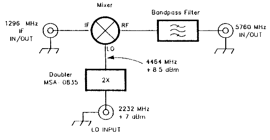
Fig 1 - Block diagram of the 5760-MHz transverter.
Fig 1 shows the block diagram of the5760-MHz transverter board, and the schematic is shown in Fig 2. There are three basic sections: LO doubler, mixer and bandpass filter.
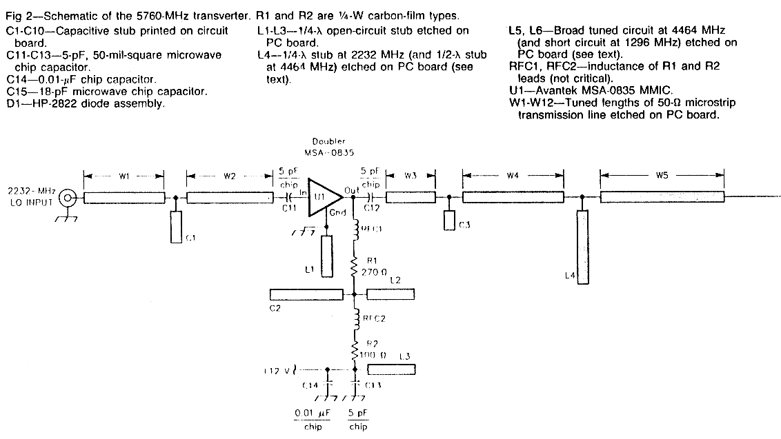
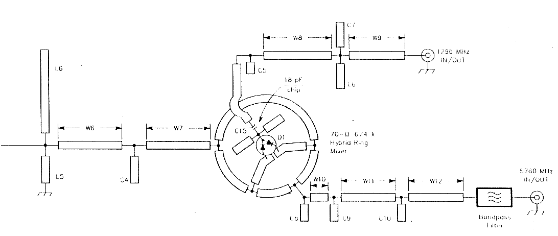
Fig 2 - Schematic of the 5760 MHz transverter.
A 4464-MHz 1.0 signal is mixed with a 1296-MHz IF signal for operation at 5760 MHz. The transverter requires an external 2232-MHz LO; an on-board MMIC doubles this signal to 4464 MHz at +8.5 dBm for mixer injection.
Although you can use any 2232-MHz source, I highly recommend the no-tune LO system described in July 1989 QST.(9) The no-tune 1_0 with a 93-MHz crystal delivers a 2212 MII7, ±7 dBm signal.
An on-board doubler using an Avantek MSA-0835 MMIC provides an output of + 8.5 dBm at 4464 MHz, with all other out- puts more than 3Q dI3 down. The second harmonic of the drive signal is obtained by overdriving the MMIC amplifier. The harmonic output is increased by reducing the MMIC bias below the value recommended for linear operation. In the reduced-bias condition, the MSA-0815 will oscillate if the drive signal is removed. A 2232-MHz drive signal of -8 dBm or more is sufficient to stabilize the MSA-0835, and the 4464-MHz output varies little for drive levels between + 3 and + 10 dBm. The MSA-0835 doubler should be driven by a broadband, flat 50-ohm source. The MMIC in the output of the no-tune 2232-MHz LO is ideal.
The output of the doubler passes through a 2232-MHz notch filter (L4 on the schematic) and a single-tuned circuit at 4464 MHz (15 and 1.6). L4 is an open-circuit ¼-λ transmission line at 2232 MHz, so it appears as a short circuit at the drive frequency. L4 is an open-circuit ½-λ transmission line at 4464 MHz, so it appears as an open circuit at the desired second harmonic. The open circuited end of L4 is one-half wavelength away from the output of the MSA-0835 at 2232 MHz and one wavelength away at 4464 MHz, so the MSA-0835 does not see a short circuit at either frequency.
The MSA-0835 is a broadband amplifier, with a noise output from dc to more than 6 GHz. If the MSA-0835 noise output at 1296 MHz is passed to the mixer, some of it will appear at the IF port. This noise will directly add to the receiver noise figure. The broadband 4464-MHz single-tuned circuit (L5 and L6) was added to the artwork to stop the 1296-MHz noise component from getting to the mixer. Careful measurements with the single-tuned circuit indicate that the noise figure is approximately equal to the mixer conversion loss. Without L5 and L6, the noise figure is about 10 dB worse.
When properly driven, this frequency doubler is well behaved, clean and stable. The six versions constructed to date have shown less than 0.5 dB variation in output level when driven from the same 2232-MHz no-tune LO.
The mixer is a standard design, except that the HP-2822 diode pair is used well above its specified frequency range. On the assumption that the imperfections of the diodes were reactive and relatively uniform from part to part, I built a standard 6/4-λ mixer, then added tuning "confetti" empirically to improve the conversion loss. The confetti was then added to the mixer artwork, and subsequent mixers show good uniformity.
Microwave Grid Hopping
June in Michigan's Keweenaw Peninsula (grid squares EN56, EN57 and EN67) is perfect for any kind of outdoor activity. Previous experience with communicating over 10-mile paths using 19-inch dishes and 3456-MHz mixer-only rigs proved that microwave hiutopping is a great way to spend an afternoon.
With a quick introduction to the "KK7B 9EFGH(*) Bandswitched Rover" station (it works on 902, 1296, 2304, 3456 and 5760 MHz), Jim, K8OSF, set off in his pickup truck for the wooded hills of EN56 in search of his first microwave contacts. After locating a likely spot with only a few trees (there are trees all over upper Michigan), he connected the 12-V battery and antenna cable to the rig and began listening. For Jim, an experienced Morse operator, making a microwave SSB or CW contact was similar to operating on the HF bands, except that the complete absence of QRM made it easier to dig for weak signals. The only signal on the 5760-Mz band that afternoon was KK7B, a few decibels above the noise. After making a minor adjustment to the tripod-mounted 19-Inch dish, the signals came up to 10 dB above the noise, and both K8OSF and KK7B switched to SSB.
The K8OSF hilltop location was 7 miles from my home QTH. There were a few small trees at both ends of the path. The two stations were virtually identical: K8OSF used a camera-tripod-mounted 19-inch dish, a 5760-MHz no-tune transverter board, a no-tune 1296-MHz transverter board for the first IF and an FT-290R for the 2-meter IF transceiver. Everything was the same at KK7B except for the TR-751A 2-meter IF. Neither station used 5760-MHz amplifiers for transmit or receive.
Contacts like this are a good way to get started on the higher microwave bands. As you gain experience, contacts over greater distances will be easy.
KK7B
* Each character of this group is an ARRL Contest Branch band designator: 9 = 902, E 1296, and so on.
The IF port is also empirically matchedto 50 ohms at 1296 MHz. The bare mixer displays a conversion loss of only 6.5 dB at 5760 MHz, which is much better than many commercial mixers designed for broadband performance in this range.
The filter is an off-center-tapped 0.16-dB-ripple Chebyshev type designed using the procedure described by Beebe.(10) It is exceptionally flat, has steep skirts and a loss of well under 1 dB in the passband.
| General | |
|---|---|
| Frequency Range | 5650-5925 MHz. |
| IF range | 1240-1300 MHz. |
| LO required | 2.18-2.32 GHz at +7 dBm nominal; +3 to +10dBm acceptable. |
| Power requirements | 12 V dc at 10 mA; 8-15 V acceptable. |
| Transmitter | |
| Output power at 1 dB compression | -6 dBm. |
| Saturated RF output | -4 dBm. |
| LO signal at RF port | -36 dBm, max. |
| IF drive level | approx 0 dBm. |
| Receiver | |
| Noise figure | 9 dB. |
| Conversion loss | 7 dB. |
| Image rejection | >30 dB. |
After I integrated the doubler, mixer and filter onto a single board, the interconnecting line lengths and tuning confetti were varied to obtain best performance with 50-ohm pads on all ports. The output spectrum at the 1-dB compression point is shown in Fig 3. The image, which is 32 dB lower than the 5760-MHz output, is off the lower end of the spectrum-analyzer range. Table 1 lists the transverter specifications.
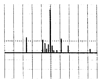
Fig 3 - Output spectrum of thn 5760 MHz transverter. Each vertical division is 10 dB; each horizontal division is 500 MHz. The pip at the center of the display is the 5760-MHz signal. All other outputs are more than 30 dB down.
One cautionary note: Any metal box big enough to hold the transverter board will be a resonant cavity at a series of frequencies within the gain bandwidth of the MMIC. Imagine building a 40-meter linearamplifier in a box the size of a football field! No-tune transverters and LOs that work perfectly on the bench often exhibit spurious oscillations when enclosed in a metal box. The transverter board will work fine if it is simply wrapped with plastic-bubble packaging material or nonconductive foam and mounted near the antenna feed. For permanent installations, a plastic food container works well.
If a shielded metal box is necessary, I recommend shielding individual stages with thin brass or copper shim stock and thenenclosing the shielded individual stages in a larger box. Spurious oscillations in the no-tune LO or lower-frequency transverters may often be cured by replacing "hot" MMICs like the MSA-0835, MSA-0685 and MAR-6 with well-behaved parts like the MSA-0235, MSA-0285 and MAR-2.
Construction
The transverter is constructed on 0.031-inch-thick Teflon®-glass substrate with a dielectric constant of 2.5. The board is clad with ½-ounce copper on both sides.
One side is etched; the other is unetched and acts us a ground plane. The material I used is made by Taconics Plastics, Ltd, Petersburg, NY 12138, and the part number is TLX-9-0310-R5/R5. The filter requires that dimensional tolerances of ±0.001 inch or better be maintained in the fabrication of the board. (Close construction tolerances are essential for microwave filters that require no adjustments.) Because of the critical tolerances necessary and the many variables involved in the QST printing process, an etching pattern is not included in this article. If you are interested in making your own board, send an SASE to the ARRL Technical Department for a dimensioned copy of the artwork.(11) Or, if you wish, you can purchase an etched board from Down East Microwave.(12)
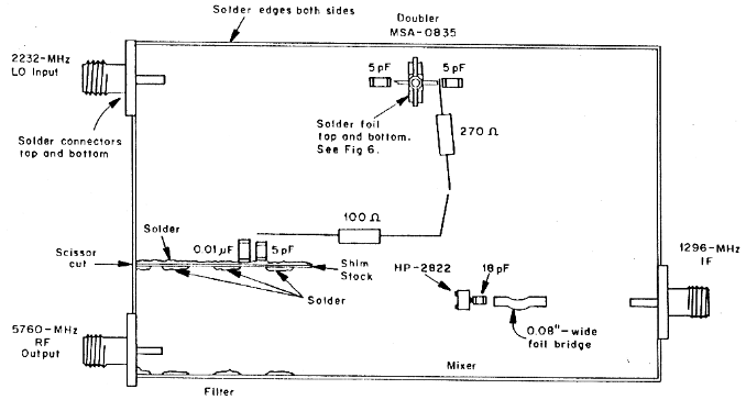
Fig 4 - Part-placement diagram for the 5780-MHz transveter board (not shown actual size). All components mount on the etched side of the board. See Fig 6 for mounting details for the MSA-0835 MMIC.
Part placement is shown in Fig 4. All components mount on the etched side of the board, and construction is conventional for microwave circuits. Additional details may be seen in Fig 5.
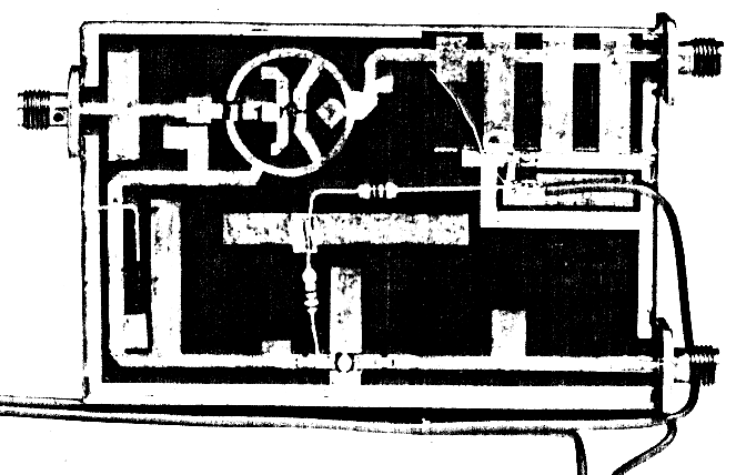
Fig 5 - A finished 5760-MHz transverter.
Brass sides enclose the board to support the SMA connectors and provide continuity between the grounds on the top and bottom of the board. The sides are made from strips of 0.032-inch-thick, 1/4-inch-wide copper or brass shim stock available at hobby stores. The perimeter of the inside walls is soldered to the top and bottom of the board. This provides a ground connection to the component side in several places, as well as a ground for the connectors.
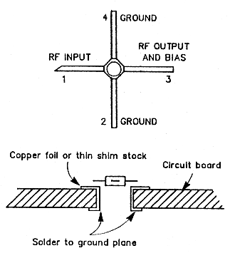
Fig 6 - Mounting details for the MSA-0835.
Additional grounding is needed for the MSA-0835. Cut a hole in the board as shown in Fig 6, and wrap copper foil through the hole to connect grounds on the top and bottom of the board. Then solder ' the foil on both sides.
Both ends of the filter elements must be grounded. The ends of the elements along the edge of the board are grounded simply by soldering them to the vertical board edge strips, which must also be soldered on the bottom. The ends of the elements toward the center of the board are grounded bymaking a straight scissor cut as indicated by the arrows, and inserting a strip of thin copper shim stock the full length of the slit. Then solder the shim stock to the PC-board copper on both sides of the slit, on the top and bottom of the board.
Additional copper foil is used to make a bridge between the 1296-MHz IF connector and the mixer. Cut the foil to 0.08-inch wide and solder one end to the printed trace from the IF connector. Then bend the foil into an arch over the printed mixer ring and solder it to the pad leading to the 18-pF coupling capacitor.
Completing Your 5760-MHz Station
In addition to the transverter and LO boards, you'll need an IF radio and antenna. There are two convenient approaches to the IF rig:
- Use a 1296 MHz multimode transceiver (ICOM, Kenwood and Yaesu make suitable radios).
- Build a 1296 MHz no-tune transverter board(13) to use as a first IF, and use a 2-meter multimode radio as the IF transceiver.
In either case, it's worth a look at Zack (KH6CP) Lau's transverter control circuit described in August 1988 QEX.(14)
Selecting an antenna for 5760 MHz is easy: Nothing matches the performance of a small dish. I've had good success with a 19-inch dish that mounts easily on a small camera tripod. It shows a 10-degree beam-width and about 25 dB gain with a simple feed. Don Hilliard, W0PW,(15) and Tom Hill, WA3RMX,(16) have presented some excellent antenna ideas for 5760 MHz.
Conclusion
This transverter board, used with the no-tune 2232-MHz 1.0, provides a straightforward approach to a transceive system on the 5760-MHz band. Although it's not as attractive as the previously described transverters for 902 through 3456 MHz in terms of output level, noise figure and the use of a 144-MHz IF, it is by far the simplest board in the family. Construction of a high-performance transceive system should be relatively easy for an experimenter ready to move up to the 5760-MHz band.
Acknowledgments
I thank Tony Bickel, K5PJR, Merle Cox, W7YOZ, and Jim Davey, WA8NLC, for inspiration and encouragement, and Mark Schreiner, NK8Q, Dave Erickson, N9JBI, and Jim Berner, K8OSF, for help in evaluating the prototype 5760-MHz transverters.
Notes
- R. Campbell and D. Hilliard, "A Single Board 900 MHz Transverter with Printed Bandpass Filters," Proceedings of Microwave Update '89, pp 1-8. This book is available from ARRL for $12 (plus $2.50 postage and hapdling, or $3.50 for insured parcel post or UPS), or from your local dealer.
- R. Campbell, "A Single Board No-Tuning 23 cm Transverter," Proceedings of the 23rd Conference of the Central States VHF Society, pp 44-52. This book is available from ARRL for $12 (plus $2.50 postage and handling, or $3.50 for insured parcel post or UPS) or from your local dealer.
- J. Davey, "A No-Tune Transverter for 3456 MHz," QST, Jun 1989, pp 21-26.
- J. Davey, "No-Tune Transverter for 2304 MHz," Proceedings of Microwave Update '89 (ARRL, 1989), pp 30-34. See note 1 for ordering information.
- See note 3.
- Copies of this article are available from the ARRL Technical Department Secretary for $2 and an SASE.
- A. Ward, "Simple Low-Noise Microwave Preamplifiers," QST, May 1989, pp 31-36, 75.
- Contact Avantek, 3175 Bowers Ave, Santa Clara, CA 95054, tel 408-727-0700, for the name of your local dealer.
- R. Campbell, "A Clean, Low-Cost Microwave Local Oscillator," QST, Jul 1989, pp 15-21.
- G. Beebe, "Analysis of a Class of Microstrip Bandpass Filters," MSEE thesis, Michigan Technological University, February 1988.
- Send a no. 10 SASE to the ARRL Technical Department Secretary; request the October 1990 QST 5760-MHz transverter template.
- Etched circuit boards, parts kits and assembled and tested circuit boards for this project are available from SHF Systems through Down East Microwave, Box 2310, RR 1, Troy, ME 04987, tel 207-948-3741. Circuit boards for the other transverters and the no-tune 2232-MHz LO referred to in the text are available from the same source.
- See note 12. Also see Z. Lau, "Product Review: SHF Systems 1240K 1296-MHz Transverter Kit," Feb 1990 QST, pp 33-34.
- Z. Lau, "A VHF/UHF/Microwave Transverter IF Switch," QEX, Aug 1988, pp 3-4.
- D. Hilliard, "Antenna Ideas For 3.5, 5.8, and 10.4 GHz," QEX, Jan 1988, pp 3-5.
- T. Hill, "A Triband Microwave Dish Feed," QST, Aug 1990, pp 23-27.
KK7B, Rick Campbell.