Parasitics revisited 2
Part 1 of this article appeared in QST, Sep 1990, p 15-18.
Before adding AG6K's latest parasitic suppressors for a complete cure, you may need to repair a blasted tuning capacitor or band switch.
Part 1 of this article reviewed the mechanism of VHF parasitic oscillation and showed how VHF parasitics damage amplifier tubes. In this article, the second of two parts, I'll describe parasitic-oscillation damage to tuning capacitors and band switches, and how to repair it; and how to build and install better parasitic-suppression networks than those I described in October 1988 QST.(6)
Title photo: The grid cage and cathode structure of an 8874 amplifier tube. VHF parasitic oscillation removed most of this grid's gold plating and sputtered some of it onto the cathode, poisoning the cathode and impairing the tube's performance. The grid cage is approximately 13/32 inch in diameter. (tube courtesy of Pus Healy, NJ2L)Band-Switch and Tuning-Capacitor Damage
VHF-parasitic-oscillation damage to band switches and tuning capacitors is the result of high VHF voltage in the amplifier anode circuit. This causes arcing, which melts and/or burns switch and capacitor materials.
Band-switch damage can occur in two forms:
- Band-switch contacts burned so badly by VHF energy that they no longer make contact. In some cases, the contacts may be missing because the arcing vaporized them! The fix: Drill out the rivets and replace the burned contacts, or replace the defective switch wafer after installing better (lower-VHF-Q) parasitic-oscillation suppressors, cathode-circuit protection and an HV fuse resistor in the amplifier.
- Conductive material deposited by the arc on the surface of the band-switch's ceramic insulation. Even if better parasitic suppression is successfully applied to the amplifier, this problem must be corrected because such conductive paths can arc during normal amplifier operation.
When the arc vaporizes and burns handswitch contacts, carbon black and gasified metal are deposited on the switch's (usually) ceramic insulation, which is indirectly heated by the arc. These conductive substances stick to the ceramic like glaze on pottery. Cooled, the glazed-on carbon and metal are difficult to remove.
The fix: If you know where the band switch arced, and minimal arcing occurred, you may be able to remove the metal particles with 400-grit wet or dry silicon-carbide abrasive paper, applied tinder dripping water. Polish and dry the ceramic, and coat it with suitable HV-insulating paint to reduce the possibility of the arc recurring at the original site. Frequently, however, the only fix for compromised hand-switch insulation - especially if the arc has been allowed to continue for some time - is to replace the switch wafer concerned. (Don't discard the damaged wafer! You can salvage its undamaged contacts and use them to replace damaged contacts on band-switch wafers that don't have arc-contaminated ceramic.)
Tuning-capacitor problems
VHFparasitic-voltage-related arcing can pit, blister, and even partially melt the metal plates of an air-dielectric variable capacitor. The resulting surface roughness reduces the capacitor's working-voltage rating. If the arcing was severe and occurred for a long time, the pitted plates may arc when normal MF/HF voltage is applied. Fortunately, unlike the damage caused by arcing in delicate band switches, this problem is easy to fix.
Insert a thin, flat file between the capacitor's plates. File them smooth and round their sharp edges, taking care to collect and discard the filings. Realign any bent plates with long-nose pliers; the air gap between all surfaces on the adjacent plates of the fully meshed capacitor must he equal. Don't worry if part of a plate has been destroyed: Tuning capacitors function well even when a corner of a plate has been completely burned away by the parasitic.
Do not repair a parasitic-damaged capacitor before you rid the amplifier of parasitics. A parasitic-oscillation arc occurs in or across the anode-circuit component with the lowest breakdown voltage. With luck, that component will he the tuning capacitor; I say "with luck" because tuning capacitors are easily repaired. If, however, you increase the tuning capacitor's breakdown rating by judicious filing and plate realignment but do not cure the amplifier's parasitics, the next parasitic oscillation may arc at the output-network band switch instead - with unpleasant and uncheap results. Replacing all_ or part of a band switch can ruin the better part of a Saturday morning or radio contest!
Stopping Parasitic Oscillations at the Source
A parasitic suppressor reduces the Q of the amplifier's anode VHF parallel self-resonance, lowering the amplifier tube's load resistance at VHF. This swamps circulating current at the VHF-self-resonance frequency and - if the suppressor is successful - reduces the tube's VHF gain enough to keep it from oscillating at VHF.
Classical amplifier designs use copper strap, often silver-plated, between the amplifier-tube anode cap and associated components. Such conductors support high-Q VHF anode resonances. Coiling the strap into a few turns and connecting a carbon-composition resistor across the coil - the standard approach to VHFparasitic-oscillation suppression in classical amplifier designs - does not appreciably lower the circuit's VHF Q because of the excellent VHF conductivity of the strap.
In the October 1988 article, I described how to construct parasitic-suppression networks that consist of lossy, low-Q inductances paralleled by low-value metal-film resistors. These worked better than the classical suppressors they replaced. Since the October 1988 article was published, 1 have learned how to build even better parasitic suppressors that are easier to make than their predecessors.
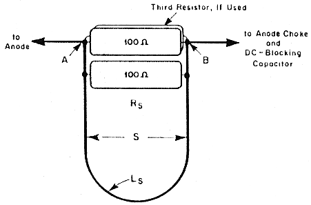
Fig 7 - A U-inductor suppressor. The network inductor, Ls, consists of a single loop of no. 18 nichrome-60 wire; the network resistor, Rs, consists of two or three 100-U, 2-W metal-film resistors soldered across the U. For typical 3-500Z amplifiers, the wire length between A and B is = 3.5 inches, producing an Ls of = 60 nH; for lower-voltage amplifier tubes, you can increase A-B to 4 inches for an Ls of =80 nH. The maximum spacing between the inductor sides (S) is set by the length of the resistors that make up Rs. Decreasing S (by squeezing the sides of the U) lowers the inductance of Ls; in some amplifiers, this may bo necessary to reduce the amount of energy dissipated by the network when the amplifier is used at 10 meters. (lt is normal for an effective VHF-parasitic suppressor to get hot during 10-meter operation because this band is closest to the parasitic-oscillation frequency.)
Better Parasitic Suppressors
If room in the amplifier box allows its installation, a U or hairpin inductor (Fig 7) offers some advantages over a conventional coil for use as the suppressor inductor: A U affords less inductive coupling with its associated suppressor resistor, and the U's inductance can be adjusted without desoldering and adding or removing turns. This latter feature is useful if, for example, the suppressor inductance must be decreased slightly to reduce suppressor-resistor dissipation at 28 MHz.(7) The inductance is lowered by squeezing together, or increased by spreading, the two sides of the U.(8)
A metal-film resistor mounted coaxially within a solenoidal inductor tends to couple magnetically to the inductor. This is undesirable in a low-Q parasitic-suppression network because the two magnetically-coupled inductances tend to act as one inductance and sharpen the response - raise the Q - of the network. Two inductances - in this case, the suppressor inductance and its associated metal-film resistor - that are not magnetically coupled are more likely to support multiple resonances. This lowers the Q of the LR network and broadens its frequency response - just what's required in a low-Q VHF-parasitic-suppression network.(9) A U-shaped suppressor inductor encourages this decoupling.(10)
In summary, the two current paths in a low-Q, LR VHF-parasitic-oscillation suppressor should he magnetically isolated. The O of each path should he as low as pos sible without causing the suppressor to melt down at 28 MHz, and the inductance in one path should differ slightly from that in the other.
The lower-inductance current path is usually that through the suppressor resistance (Rs). In an LR suppressor constructed for a 3-5002, the inductance of Rs is roughly 20 nH if the resistor is installed with nearly zero lead ktigth, while the suppressor inductor, Ls, exhibits an inductance of 60 to 80 nH.
Applying almost any component involves trade-offs and caveats, and U-inductor suppressors are no exception. In multitube amplifiers, U inductors present a potential but avoidable problem: If the inductors are positioned so that they couple (positioning them in the same plane may support this) or talk to each other, they may encourage a push-pull parasitic oscillation (three symptoms of which ate very high anode current and dissipation, but no arcing). This problem can be avoided by positioning the U inductors so that they are not in the same plane. (Ideally, the planes of adjacent U inductors should he at 90° to each other. This can be accomplished by rotating the plane of one U 45° to the left and rotating the plane of the adjacent U 45 ° to the right.) In amplifiers with three or more tubes, positioning U-inductor suppressors for minimum intersuppressor coupling may require considerable experimentation.
Solving Stubborn Cases
I have come across some amplifiers that cannot be cured of occasional parasitic oscillations by the use of a single parasitic suppressor, even if the suppressor is of an improved design with a low VHF Q. One common reason for such persistent parasitics is that, in some amplifiers, the suppressor may make up less than half of the total conductor length in the anode circuit. If most of the anode-circuit conductor has a high VHF Q, the overall Q will be higher than optimum for parasitic suppression even if a lowest-possible-Q suppressor is used. In such amplifiers, the high-VHF-Q anode conductors must be replaced with low-VHF-Q conductors. To do this, replace the anode circuit's copper straps and bus wires with two magnetically decoupled wire conductors made from a low-Q material, such as nichrome wire (Fig 8). (Although nichrome ribbon is prettier to look at than nichrome wire, don't substitute nichrome ribbon for wire in this application unless the wire overheats at 28 MHz. Nichrome wire is generally preferable to nichrome ribbon because skin effect causes round conductors to exhibit more VHF resistanceand lower VHF Q than ribbon conductors of the same cross-sectional area.)
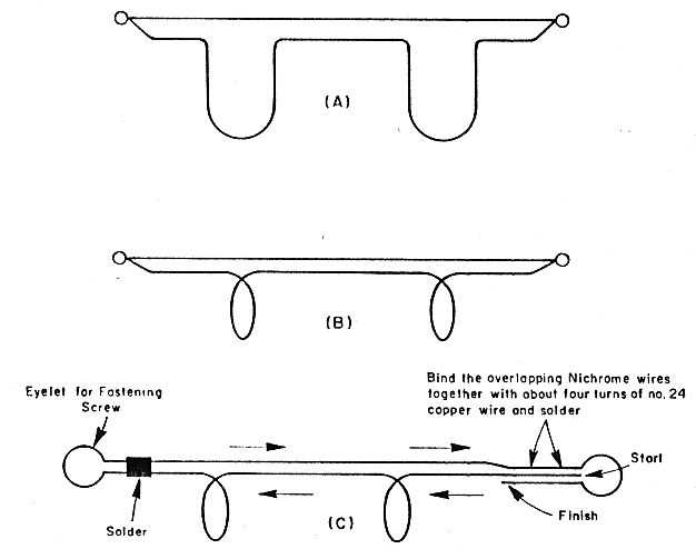
Fig 8 - Killing stubborn VHF parasitics may require the substitution of low-VHF-Q conductors for an anode circuit's high-Q straps. Paralleled straight and Inductively loaded nichrome-60-wire runs are one answer. The loading inductors can take the form of Us (A) or single-circular-turn coils (shown in side view, at B, as loops). C shows a method of constructing such a low-VHF-Q conductor from a single length of nichrome-60 wire.
To create the desired double-resonance effect, make one of the wires as short as possible (usually straight) and the other slightly longer. Take up the slack in the longer wire by forming it into ¼-inch-ID, 1- or 2-turn coils. Use more than one coil for long runs. If most of the magnetic field around each inductor is at right angles to the magnetic field around the straight wire, the desired double-resonance/Q-lowering effect will be realized. To accomplish this, make the axis of the coils parallel to that of the straight conductor.
Although nichrome works well for constructing low-VHF-Q suppressors, a nichrome alloy---one containing a small amount of iron - is available that produces a lower-VHF-Q suppressor than the ordinary 80%-nickel/20%-chromium alloy.(11)
The Effect of Tube Gain
A major factor affecting the stability of an individual MF/IIF amplifier is the VHF gain of the particular tube, or tubes, in the amplifier. There appears to be some tube-to-tube VHF-gain variation, even among those bearing similar manufacturing-date codes. I know of several cases where nn amplifier was quite well behaved until a different, and not necessarily new, amplifier tube was installed. For example, two commercial 8877 amplifiers had played well for years, each with its original tube. When a new tube from a factory-sealed box was tested, each amplifier sustained a majoras in big bang - VHF parasitic oscillation. In both cases, the new tube was destroyed. Another new tube was tried in one of theseamplifiers. The second new tube met the same fate as the first replacement.
VHF Input Loading: Another Weapon Against VHF Parasitics
Another method of reducing a tube's VHF gain is to provide a low-VHFresistance path to chassis ground at the cathode terminal(s) on the tube socket. This swamps the VHF signal fed back from anode to cathode via the tube's internal capacitance. A practical parasitic suppressor of this type consists of a metal-film resistor in series with a small-value capacitor. (Typical values are 25 pF and 1 to 10 Ω) The object is to find a value of capacitance that resonates with the tube's inductive input reactance at the parasitic frequency. When this is done, the series-resonant circuit consisting of the tube inductance and added capacitance looks like a low resistance and routes the VHF-feedback energy to ground through the metal-film resistor. (The resistive component is essential for another reason: A capacitor, used alone, ' may exhibit a highVHF-Q self-resonance that might aggravate the parasitic problem. The resistor lowers ("kills") the Q of the capacitor's self-resonance.)
This VHF input-swamping technique is especially useful with tubes such as the 3CX1200A7 and 3-1000Z, which exhibit about four times more plate-to-cathode feedback capacitance than other tubes of similar power capability. For these tubes, one RC network consisting of a 10-0 resistor in series with a 25-pF capacitor, between each filament terminal and the chassis, seems to work well. Since this effectively adds about 50 pF to the output capacitance of an amplifier's input x network, you may need to compensate for the presence of the suppression network by reducing the capacitance contributed by the network's stock output capacitor(s) at the upper high frequencies. Alternatively, increase the affected network's input capacitance by about 50 pF and adjust the network inductor for less inductance (and a good input SWR). Because this latter approach slightly increases the input-network Q, it usually results in a lower 10-meter input SWR than the amplifier originally exhibited.
Because the inductance resonated by the cathode-to-ground RC network is internal to the tube, the frequency of the series resonance that occurs when the cathode-toground RC network is installed cannot be checked with a dip meter. Thus, there is no method of optimizing the RC-network lead lengths and values for optimum VHF input loading other than to make an educated guess followed by lrial and error.
I strongly recommend protecting the tube with a grid-fuse resistor during the trial-and-error period. In amplifiers that do not ground the grid directly via a spring-finger collet, connect the fuse resistor - typically, a 24 to 30 Ω, ½ W unit - from one grid pin to chassis ground. Be sure the resistor is sufficiently bypassed for RF to keep it from dissipating too much power at the amplifier operating frequency. In a typical 3-500Z amplifier, the bypass capacitance should be at least 1.8 nF; larger tubes, such as the 3-1000Z or 3CX1200A7, require at least 2.7 nF because these tubes' higher CAO causes more output-network circulating current to flow through the grid to ground than is the case with lower-capacitance tubes.
In amplifiers that use a grid-grounding spring-finger collet, install the grid-fuse resistor between the grid-current-meter shunt resistor and chassis ground. (This case also requires a different cathode-overvoltage clamper than discussed in Part 1 [and Fig 5] of this article: Replace the series-connected 3-A diodes shown in Fig 5 with a 50-V ac MOV surge suppressor capable of carrying several thousand amperes - a less-than-two-dollar part even at single-unit prices.)
Tracking Parasitic Oscillations
VHF parasitic oscillations are difficult to document. "Sniffing" the amplifier anode circuit with a spectrum analyzer may show the parasitic - if the oscillation persists long enough to be picked up by the analyzer's sweep. A VHF-capable oscilloscope - preferably one capable of capturing and storing input signals - and sniffer probe may be able to indicate the presence of the parasitic, but it's difficult to make reliable frequency determinations with an instrument intended to display amplitude v time.
Of course, the resonant circuit that supports the parasitic is very likely to still be there when the amplifier is unpowered and unplugged, and a dip meter can reveal itsresonant frequency. If you want to measure the resonant frequency of the amplifier-box cavity, all of its covers must be in place, with all of their fastening screws moderately tightened. You can couple the dip meter to the cavity via a small continuous loop of wire passed through the box's ventilation holes.
If you would like to observe the effect of installing different parasitic suppressors, check the stock anode circuit's VHF resonance before making any modifications. Couple the dip meter to the conductor between the anode connection and the output-network tuning capacitor; a spot near the tuning capacitor will probably provide the best indication. The anode circuit usually resonates between 65 MHz (large amplifiers) and 170 MHz (small amplifiers using a single UHF-rated tube).
In many unmodified amplifiers, the VHF anode-circuit dip is so sharp that it "sucks out" - stops - the dip-meter oscillator.(12) This indicates that the anode circuit has a very high VHF Q - not good news airless you happen to need a combination self-excited VHF oscillator/mini-lightning-bolt generator/tube destroyer!
After installing low-VHF-Q parasitic suppressors, recheck the dip. Usually, its frequency will not have changed appreciably, but the dip should now be smooth and broad, allowing closer dip-meter coupling without suckout. If you observe this, you have substantially reduced the VHF Q of the amplifier's anode circuit, and the amplifier should be much more stable - even at MF/HF.
Better stability directly relates to the fact that many amplifier users observe that their amplifiers tune up more smoothly and predictably after low-VHF-Q parasitic suppressors have been installed. This was the case with my Heathkit® SB-220. In its stock configuration, a disconcerting double output-power peak occurred as I tuned the amplifier on the 40-meter band. Would the real peak please stand up! For years, I was puzzled about this, and by the occasional minor arcing in its output circuitry. After I installed better - that is, low-VHF-Q - parasitic suppressors, the extra dip vanished, along with the arcing. Another example: Drake L-4B amplifiers frequently exhibit a tune-up vagary on 15 meters; this anomaly goes away after better suppressors arc installed.
Summary
VHF parasitic oscillations capable of destroying expensive components are common in high-power, vacuum-tubebased MF/HF amplifiers. Although I know of no esoteric or magic amplifier layout technique for eliminating VHF resonances in MF/HF-amplifier circuitry, the ability of such resonances to support VIII: parasitic oscillations can be reduced enough by simple circuit modifications that VHF parasitics do not occur. Only a dip meter is required to determine whether or not a given parasitic-reduction campaign is on the right track, and simple protective circuitry can be added to an amplifier toensure the safety of amplifier tubes and other expensive components during the anti-parasitic R and D process. I hope that my description of these techniques will help you rid your amplifier of VHF parasitics once and for all.
Notes
- R. Measures, "Improved Anode Parasitic Suppression for Modern Amplifier Tubes," QST, Oct 1988, pp 36-38, 66 and 89.
- See R. Measures, "Calculating Power Dissipation in Parasitic-Suppressor Resistors," QST, Mar 1989, pp 25-28.
- Although this seems counterintuitive, reducing the space between the u's sides is not the same as reducing the interturn spacing of a multiturn coil. At any given instant, current flow through the u's strap is uniform and unidirectional. Because the strap is bent back on itself, one side's current flow (and hence, its magnetic field) opposes that of the other side. Opposite fields tend to cancel; reducing the space between the u's sides increases this cancellation. The net effect is that the U's inductance decreases as its sides are brought closer together. - Ed.
- This principle can be used to make a broadband 75/80-meter dipole: One 1/2-X dipole, cut for 3900 kHz, is connected to the feed point of another 1/2-k dipole cut for 3600 kHz. The dipoles are oriented so that they are 90" apart, such as north-south and east-west. The result is a low SWR across the entire band. If the 90° separation is reduced, the inductive decoupling afforded by the dipoles' perpendicularity is reduced, and the composite antenna's SWR bandwidth decreases.
- U-inductor suppressors may have another advantage: They appear to couple to the RF-deck cavity better than a solenoidal inductor. Suppressor-to-cavity coupling resistively loads the cavity and damps its ability to ring (and support oscillation) at RF. (Some commercial amplifiers accomplish this by placing a resistively loaded VHF antenna in the cavity. This appears to work well if the loading antenna is cut for the frequency at which the parasitic would oscillate if the cavity were unloaded.
- Although some of the available literature suggests that iron should not have much effect at VHF, tests on a Boonton Q meter indicate a Q decrease of about 20% at 50 MHz (the upper limit of the instrument) for the nickel-chromiumiron alloy.
- Dip meters dip because the resonant circuit under test absorbs energy from the oscillating dip-meter circuit. Coupling the dip meter too closely to the circuit under test - that is, allowing the circuit under test to absorb too much energy from the dip-meter oscillator - can stop the oscillator or unnecessarily broaden the dip. If this happens, back the dip meter away from the circuit under test until the meter oscillates throughout the dip and the indicated resonant frequency is the same regardless of which way you tune the meter through the dip.
AG6K, Richard L. Measures