An improved input circuit for parallel-tube VHF power amplifiers
A current trend In the construction of multiple-tube VHF power amplifiers is to use parallel rather than push-pull connection. Over the years, a number of articles have appeared describing the use of two (and even three) 4CX250s in parallel as replacements for the venerable W1HDQ "plumber's delight" push-pull pair on 144 and 432 MHz.(1-4) The primary advantage of the parallel-tube circuit is that it greatly reduces the effects of tube and plate-circuit imbalance, which can lead to nonlinearities in push-pull operation.
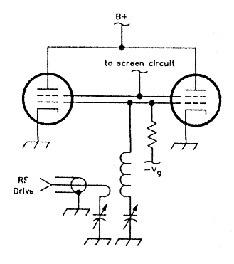
Fig 1 - This Input circuit offers no consistently reliable method for balancing the drive between the two parallel-connected tubes.
In the input circuit of a typical paralleltube amplifier, the grids of both tubes are connected in parallel and matched to 50 ohms with a double-tuned, link-coupled circuit (see Fig 1). This circuit has virtually no latitude for balancing drive between tubes, thus eliminating one of the main advantages of parallel connection. A similar situation exists for amplifiers using cathode-driven tubes such as the 8874 or 3CX800A7. Parallel connection of tube cathodes is okay at MF/HF, but can lead to problems at VHF and above. An additional problem encountered when cathodes are connected in parallel is increased difficulty in metering the individual tube currents - a must when tubes are so expensive.
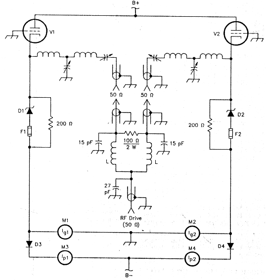
Fig 2 - With this input circuit, drive balance is achieved easily. For 144 MHz, the two inductors labeled L each consist of 4 turns of no. 20 enameled wire, 1/8 inch diam, 1/2 Inch long with a total winding length of 5/8 Inch.
An input circuit that we recently tried with a parallel-connected pair of 3CX800A7s for 144 MHz is shown in Fig 2. Each tube cathode is matched to 50 ohms using a network that also provides a series input capacitor for dc blocking.(5) The two 50-ohm ports are fed in phase using a lumped-element Wilkinson power divider. The divider also provides up to 30 dB of port-to-port isolation, eliminating any possibility of push-pull modes between the tubes. A transmission-line Wilkinson divider or transmission-line ring hybrid would also work here.(6) Grid- and plate-current meters are provided for each tube, to allow monitoring the power split between the tubes.
During initial tune-up, SWR meters are inserted into each cathode port and the input circuits are tuned for best match and balance between the tubes. If the tube gains are badly mismatched, 50-ohm attenuation can be inserted at the input port of the higher-gain tube. The completely separate cathode dc circuits also allow balancing the resting current of each tube by using different-value Zener diodes for D1 and D2, should this be necessary. D3 and D4 keep the plate meters from shorting the grid-meter circuit.
There's no reason that this concept can't be extended to use three or even four tubes in parallel provided that the proper multiport power divider is used.
After struggling for years with various push-pull and parallel schemes on 2 meters, we've found this approach to be a breeze. Amplifier balance and stability are excellent, and the extra dissipation provided by two tubes gives plenty of performance margin even for contest and EME operation.
N3AHF, Dave McGee and KS2D, Bob Evans.
Notes
- E. Tilton, "A High-Efficiency 2-Meter Kilowatt," QST, Feb 1960, pp 30-33.
- R. Knadle, "A Strip-Line Kilowatt for 432 MHz," QST, Apr 1972; pp 49-55 (see Feedback, Jul 1972, p 47).
- S. Gross, "A Parallel 4CX2508 Amplifier for 144 MHz," QST, May 1975, pp 11-14.
- D. Dobricic, "A Three-Tube 4CX250B Linear Amplifier," ham radio, Apr 1987, pp 63-72.
- D. Meacham, "A High-Power 2-Meter Amplifier Using the New 3CX800A7," QST, Apr 1984, pp 11-15.
- T. Pettis, "HY-brid HI-power," QEX, Jan 1990, pp 13-14.