A new standard for amateur radio analog facsimile
Experience high-quality fax on HF, VHF and UHF! Here's an exciting, simple and inexpensive approach to fax for all.
Facsimile (fax) is the oldest of the image-transmission technologies. It evolved early in this century as newspapers developed the means to print photographs on a routine basis. With the maturation of radiotelephony, it became possible to transmit and receive high-quality still images anywhere in the world, and press organizations created worldwide communications networks to ensure that photographs of major events appeared in newspapers with minimum delay. Sending a detailed picture over voice-grade cables or wireless links requires that the rate of image transmission be quite slow. Depending on the circuit and the amount of detail required, transmission times might range from 5 to 20 minutes or more. (For more information on fax, see the sidebar, "Some Fax Basics.")
What Have Amateurs Been Doing With Fax?
Amateur fax activity has been primarily limited to a spin-off of fax, slow-scan television (SSTV) and reception of weather-satellite images. Until only a few years ago, weather-satellite enthusiasts typically modified commercial fax recorders, or built their own machines from scratch. The era of mechanical systems has now faded into history. Most current weather-satellite work involves the use of computers and high-resolution graphics display systems.
IBM PC, AT, PS/2 and PC-compatible computers equipped with VGA display systems are, by far, the most popular.
SSTV is an amateur innovation, pioneered in 1958 by Copthorne MacDonald (now VY2CM).(1) After a period of experimentation, SSTV activity settled on a standard using 120-line images, transmitted at a rate of 15 lines/second, for a total of 8 seconds per image. This method used an FM-modulated subcarrier, adopting standard fax frequencies of 1500 Hz for black and 2300 Hz for white. Because SSTV is based on cathode-ray-tube (CRT) technology, the fax standard was modified to include the use of a 1200-Hz subcarrier frequency as a sync pulse. The vertical sync pulse, to start each frame or image, is a 30-ms interval of the 1200-Hz subcarrier, while each line is triggered by a 5-ms horizontal sync pulse.
From Long-Persistence Phosphors ...
The original SSTV image format was a trade-off between bandwidth considerations and the available analog-display technology. A 15-Hz line-transmission rate (about 1920 picture elements/second [or pixels/second]) is about the maximum data-transmission rate suitable for use with HF SSB equipment. Pictures were displayed on long-persistence (P7 phosphor) CRTs that would hold a useful image for about 8 seconds. If an image is transmitted at a rate of 15 lines/second for 8 seconds, the result is an image consisting of 120 lines. While relatively crude, the results are quite acceptable for close-up portrait views (Fig 1) and the short transmission time means that at least one or two frames would dodge the QRM if you sent each picture several times.
... to Digital Memory
The advent of digital scan converters, where the image is stored in digital memory and displayed on a TV monitor, did away with the limitations of the P7 CRT. As memory-chip capacity increased (and prices dropped), amateurs experimented with 120-and 128-line color images and 240- and 256-line higher-resolution monochrome (B&W) formats. By 1985, with the introduction of the Robot Research Model 1200C scan converter, 240-line full-color images became the norm. The 240-line pictures, in B&W or color, are a tremendous improvement over the older 120-line standard and approach the resolution you see when viewing videotapes (Fig 2). As computer graphics standards evolved and improved, various microcomputers such as the Amiga, and PC compatibles with VGA graphics adapters, became more prevalent as SSTV operating platforms. Even stations using dedicated scan converters, such as the Robot 1200C employ computers to store and retrieve images, overlay call signs and otherwise manipulate the pictures.
Table 1 - Proposed Standards for the Transmission of 512 x 480 x 16 Images| Image aspect ratio | 1:1 (square) |
|---|---|
| Horizontal line rate | 3.7416 Hz |
| Direction of horizontal scan | left to right. Pixel display/sample rate: 1953.125/s. Frame scanning lines: 480 |
| Direction of vertical scan | top to bottom |
| Video modulation | audio FM subcarrier; sync, 1200 Hz; black, 1500 Hz; white, 2300 Hz |
| Line synchronization | crystal reference and/or line-sync triggered; 5.12 ms of 1200-Hz line sync, followed by 262.144 ms of active video |
| Frame start/synchronization | 5 seconds of 244-Hz modulation of the subcarrier between black and white limits (4 clock cycles of 1500 Hz followed by 4 clock cycles of 2300 Hz, repeated 1220 times), followed by 20 phasing lines consisting of 10 clock cycles of sync (1200-Hz subcarrier) followed by 512 clock cycles of white (2300-Hz subcarrier). Frame period: 2 minutes 18.3 seconds (10 seconds for start/phasing plus 480 active image lines). |
Why Was Fax Sleeping?
Although SSTV has seen steady growth, there has been almost no activity in terms of high-resolution fax work. There are two significant reasons for this: First, there's no single, coherent fax standard. Surplus commercial fax machines vary considerably in terms of standards, and it's difficult to obtain spare parts and specialized supplies (such as the multitude of different recording papers) that these machines use. Secondly, there's the length of time required to transmit a fax picture. Depending on the system, anywhere from 5 to 20 minutes are required to transmit and receive an image! For radio amateurs, because FCC. regulations require periodicstation identification, transmitting for more than 10 minutes without identifying is illegal. Even transmission times of 4 to 6 minutes are impractical, given the congested nature of our HF bands. With the heightened interest in amateur video communications, it's time we looked at alternatives for the transmission of more-detailed images.
A Computer-Based Fax Standard
Rather than tie amateur fax standards to outmoded 1930s mechanical technology, it seems reasonable to focus on available high-resolution computer video standards as a starting point. Now, IBM PCs and compatibles unquestionably have the largest installed user base. VGA graphics adapters and monitors have become the entry-level standard for such computers, and older units can be upgraded to VGA standards for as little as$50 for a VGA adapter card and about $100 for a monochrome monitor. Although VGA systems are backwardly compatible with the older monochrome, CGA and EGA standards, two VGA-specific modes have the greatest potential interest for amateur imaging:
| Pixels/Line | Image Lines | Colors/Gray Scale |
|---|---|---|
| 320 | 200 | 256 |
| 640 | 480 | 16 |
The 320 x 200 standard is widely used in systems designed for SSTV image display, although the 256-color limit demands creative programming to achieve acceptable color display. The 640 x 480 x 16 color/grayscale mode provides an excellent option for a significant increase in monochrome image resolution. If the horizontal display is limited to 512 pixels, an area to one side of the image can be reserved for image data and menu options.
A 512 x 480 image (see the lead photograph and Figs 3 and 6) represents the same increase in resolution over the 240-line SSTV standard as the 240-line pictures do in relation to the original 120-line format. The increase in image detail is striking and greatly expands the range of options for pictures and subjects.
If you've purchased a computer in the last two years, you probably already have all the computer hardware you need. All that's required to put high-resolution fax pictures on the air is a transmission standard that takes advantage of the many options already developed for SSTV.
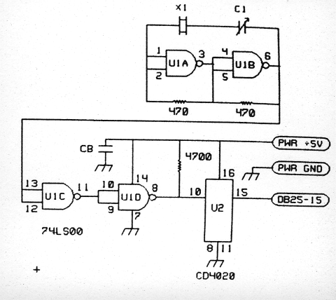
Fig 4 - The original schematic of the simple clock circuit. The circuit uses a 4-MHz microprocessor crystal. Resistors are 1/4 W, 5% tolerance carbon-composition or -film units. U1 is the oscillator/buffer, followed by U2, a CMOS counter, providing a divide by 2048 function. The GND and +5 V leads are connected to points on the bottom of the ViewPort VGA PC board at the dc power connector; the lead to pin 15 (ERROR) of the parallel connector is connected beneath the ViewPort board near the DB25F I/O connector.
Video Modulation Standards
Table 1 lists the specifications for a VGA-based image-transmission format. The standard fax and SSTV audio FM modulation format (1500 Hz black to 2300 Hz white) is retained, enabling use of existing HF fax and SSTV modems.
Line and Frame Rates
The standard specifies a 3.7416 lines/second horizontal rate. This fractional value may seem odd, but is a result of bandwidth and system clock factors. The present HF SSTV standards transmit pixels at a rate of 1920/second. Transmitting pixels at a significantly slower rate results in unnecessary extension of the image-transmission time. A significant increase in the pixel rate requires a wider video bandwidth and degrades resolution because of the audio and RF filtering used in modern HF SSB equipment. A pixel rate roughly comparable to the SSTV rate is the most practical alternative.
In the next section, I'll emphasize the benefits of maintaining very precise rates for image transmission. This can't be achieved by relying entirely on the computer's internal clock and/or software timing loops. A simple crystal clock circuit that can be trimmed to a precise frequency provides the requisite accuracy.
Tick! Tock!
We can take two approaches to the system clock. If we want a nice, even-numbered line rate, we'll need a custom-ground crystal whose odd frequency will make it difficult to adjust without a very accurate frequency counter. Alternatively, we can use a universally available crystal (cheap!) andaccept whatever line rate that produces. Fig 4 shows a simple and frugal clock circuit using a 4.0-MHz microprocessor crystal. U 1 is the oscillator/buffer, followed by U2, a CMOS counter, providing a divide-by-2048 function. Assuming the 4-MHz oscillator is precisely on frequency, the clock output is 1953.125 Hz. If a well-calibrated frequency counter is available, connect it to TP1 and adjust C 1 (use a nonmetallic tuning tool) for a reading of precisely 4 MHz. Alternatively, set the crystal calibrator of your receiver for zero beat with WWV at 10 MHz. Connect a short test lead to TP1, set the receiver to 4 MHz and adjust C1 for zero beat with the calibrator harmonic.
The system software uses this clock to time the pixel transmission and display, so the resulting pixel rate is 1953.125 pixels/second. Each clock cycle requires 0.512 ms; that sets all the other system rates. Each line is preceded by 10 clock cycles of 1200-Hz subcarrier sync (a total of 5.12 ms), followed by 512 image pixels, requiring an additional 262.144 ms (512 x 0.512). Thus, the total time required for line transmission is 267.264 ms (5.12 + 262.144). Because each line requires 267.264 ms, the line rate works out to 3.7416 lines/second (1000 ms = 267.264). The image frame consists of 480 lines, so the time required to transmit the image data is 2 minutes, 8.3 seconds (480 lines =3.7416 lines/second =128.3 seconds). We need to add an additional 10 seconds at the start of the picture to ensure reliable starting (to be discussed shortly), so the total timerequired for transmission of a complete picture is 2 minutes, 18.3 seconds.
Synchronization
SSTV image lines are triggered individually by the presence of a 5-ms, 1200-Hz sync pulse tone at the start of each line. Because the sync pulses maintain line registration at the start of each line, SSTV timing is relatively noncritical to received image display. SSTV images can be recorded on standard monaural audio-tape systems of modest quality and still retain acceptable image registration. The major drawback to line triggering is that interference or noise bursts can disrupt line triggering and thus destroy an entire line of image data.
Fax systems don't use sync pulses; they rely on precision speed control at the transmitting and receiving ends to maintain synchronization. This makes line registration independent of noise or interference; only individual pixels are disrupted on a noisy path. The main problem with such an approach is that it's best implemented live. Recording such a transmission either requires the use of a precision recording system (a VCR locked to a local TV station or a digital audio-tape system), or the use of a stereo audio recorder with crystal-referenced tones and phase-locked loops to track inevitable speed variations in the audio recorder.
The proposed standard takes advantage of the positive aspects of both the line-triggered and crystal-locked approaches. All image transmissions are made using the 1953.125-Hz master clock frequency as a standard. The image is transmitted with the same precision as a fax signal, but conventional 5-ms, 1200-Hz SSTV horizontal sync pulses are inserted at the beginning of each image line. Thus, two modes of operation are possible. Display of the signal, using the crystal clock, begins with the detection of the image-start routine (to be discussed). The system then looks for the first 5.12-ms, 1200-Hz line sync pulse (10 clock cycles). At that point, the system displays the 480 image lines entirely by reference to the crystal-controlled clock. Noise or interference impacts individual image pixels only!
Because the system also transmits line sync pulses, the signal can be recorded on a standard monaural cassette recorder. A second display routine, which loads lines after receipt of each line sync pulse, can be used to display the image from the tape recorder. Once loaded, the image can then be transmitted by reference to the system clock. The result is a very flexible system with the precision of conventional fax, but with the audio-tape convenience of SSTV!
Image Start
When I first began work on the 480-line fax format, I initiated each frame with a conventional 30-ms, 1200-Hz SSTV vertical sync pulse. This worked well all the way through the early tests on UHF FM, but was less than satisfactory when the typical 20-meter bedlam was mixed with the signal while I was experimenting on the test bench. Commercial HF fax links place a premium on reliable image starts. If their customer's machines are subject to false starts, the customer wastes money on fax paper and loses the opportunity to receive a possibly important image. For an amateur fax standard, if we're going to commit slightly over 2 minutes to the transmission of a picture, we want starting to be as reliable as possible to make optimum use of the frequency.
HF and satellite data links solve the starting problem by transmitting several seconds (typically about 5) of a distinctive start tone. The start tone consists of square-wave modulation of the subcarrier between black-andwhite limits (often at a 300-Hz rate). This start tone is quite distinctive and can be reliably detected in a number of ways, triggering the recorder at the receiving end. The start tone is then followed by a phasing interval of about 5 seconds duration. During this period, black pulses are transmitted to mark the start of image lines, with the rest of each line consisting of white subcarrier. The black-to-white transitions are easily detected and the phase interval permits the recorder at the receiving end to get into step (phase) with the fax transmitter. At that point, actual transmission of image data begins.
My experience with weather satellites had demonstrated how reliable such a system can be, so I incorporated it into the 480-line standard. The start tone for this format involves 5 seconds of a 244-Hz square wave modulating the subcarrier between black andwhite limits. This is achieved by setting the transmitted subcarrier to white (2300 Hz) for 4 clock cycles (2.05 ms), then setting it to black (1500 Hz) for 4 more clock cycles. If this is repeated 1220 times, the result is 5 seconds of start tone (1220 / 244 = 5). At the receiving end, the start tone is detected by sampling the video on every clock transition for a total of 488 samples (¼ second). The system tallies the number of black-to-white transitions in the 1/4-second interval. If the start tone is present, there should be 61 transitions (244+4). The system accepts a value between 59 and 62 (allowing for sampling error), assuring stringent requirements for initiating image display. The use of a 5-second start tone interval allows the receiving operator ample time to initiate display when the start tone is heard, further reducing the possibility of false starts.(2)
The start tone is followed by about 5 seconds of phasing interval, representing 20 nonimage lines. Each of these lines begins with 10 clock cycles of 1200-Hz subcarrier (5.12 ms), followed by 512 clock cycles of white (2300-Hz) subcarrier. This makes it very easy for the system to detect that starting time for the forthcoming image lines, at which point display can begin using either the crystal-clock reference, or triggering using the line sync pulses. With the software to be described shortly, about 10 of these white lines are displayed at the top of the picture if the start tone was detected immediately. This provides a buffer of about 3 seconds for start-tone detection under noisy conditions, without loss of image data.
Hardware
One of the problems associated with attempting to introduce a new communications standard is the vision of all the new hardware required to give it a try. This is not the case with this computer-based fax standard! Most interfaces designed to receive and transmit SSTV using a PC-compatible computer can be used to transmit and receive images using this standard. One such unit is the ViewPort VGA SSTV interface.(3), (4)
A&A Engineering's ViewPort VGA is an excellent general-purpose SSTV interface that requires the simple addition of the clock circuit shown in Fig 4 to be compatible with the 480-line fax mode. The clock circuit, built on a small piece of pert or PC board (see Note 3), can be installed in the ViewPort VGA (see Fig 5), which supplies the needed 5 V dc. The interface connects to the host computer via the parallel printer port.5 The interface uses almost all of the I/O capacity inherent in the PC's parallel port, with the exception of a single input bit available at pin 15 (the ERROR bit) of the DB25 connector on the ViewPort VGA rear apron. A single wire, connecting the output of the added clock circuit to this pin, is all that's required to put the system into fax service. The added clock circuit has no effect on the use of the interface for SSTV.
Software
The software required to implement 480-line fax is hardware-specific. To encourage experimentation in this mode, I've written a PC-compatible program, FAX480, which is being made available free of charge on a number of bulletin board systems. (A&A Engineering also ships the software with ViewPort VGA kits and assembled and tested units; see Note 3.) The software can be found on the ARRL's BBS (203-666-0578), the Dallas Remote Imaging Group (DRIG) BBS (214-394-7325) and on my Weather Satellite Handbook BBS (517-676-0368). Experimenters may copy and distribute the software to others, as long as no fee is charged and commercial use is not made of the program code. The software is distributed in an archived file (FAX480.ZIP), which contains the following files:
- FAX480.EXE - the operating program to control the A&A ViewPort VGA interface.
- FAX480.DOC - an ASCII documentation file describing the use of the FAX480 program.
- BINFAX.EXE - a utility file to convert VGA-screen-captured files to the FAX480 image-file format.
- FAXSSTV.EXE - a utility to convert FAX480-format images for use in the SSTV portion of the program.
- Receive live (directly from the computer) images using the internal crystal clock.
- Display audio-tape-recorded images using frame- and line-triggering provided by the 1200-Hz sync pulses.
- Transmit images from the RAM image buffer.
- Display, on demand, the current image in the RAM buffer.
- Save to disk and load from disk any image (128 kbyte total file size).
- Display a 16-step gray scale to optimize adjustment of the VGA monitor's brightness and contrast controls.
- Add a one-line (60-character) label at the bottom of the image. This label can identify the image and/or provide information relevant to a particular contact.
- Print fax images on LaserJet and DeskJet printers.
- An SSTV operating module that lets you receive the most-popular SSTV modes and transmit both low and "high"-resolution SSTV images from within the FAX480 program.
- Routines to permit precise receiver tuning prior to picture transmission.
Sample images, typically one 480-line fax image and several SSTV-format images are included in the archived distribution file.
With this software, you can operate two-way 480-line fax without any ancillary equipment other than the modified A&A ViewPort interface. The computer must be equipped with a VGA display adapter, a minimum of 640 kilobytes of RAM and a parallel printer port. There's no installation program: The software automatically determines the parallel port to which the interface is connected and alerts you if you've failed to connect the interface or apply power to it! The program can run from a floppy disk of virtually any capacity, or a hard disk drive. See Table 2 for a brief description of the program's features. The FAX480 program and A&A interface were used for all the onthe-air tests. This 480-line fax capability can be incorporated into other PC-based SSTV systems; I encourage developers to do so. Anyone experienced in programming SSTV routines will have no trouble, as sync and video handling is identical to that of SSTV except for reference to the clock-pulse train for timing.
Image Sources
Untold high-resolution images are available from BBSes and other sources. These images can be easily translated to a FAX480-compatible format. Terminate-and-stayresident (TSR) software is available that grabs a 640 x 480 VGA screen and converts the image to a large binary file (307 kbytes). VGACAP (V 6.1) by Lawrence and Marvin Gozum, a shareware program available on the DRIG bulletin board,6 is an example of such software. The BINFAX.EXE utility program supplied in the FAX480.ZIP archived file converts such binary files to the disk format used by the FAX480 program.
Hand-held and flatbed scanners can also be use to digitize photos and other material. Most of these support a 640 x 480 VGA display option. If these programs don't directly generate the needed binary files, the screen-grab approach mentioned earlier can be used. Hand-held scanners represent one of the most cost-effective ways to produce images for fax and SSTV. They're particularly useful in computer-based systems that may lack TV frame-grabbing hardware. Almost all the images in this article were scanned from standard color prints using a Logitech 256 hand scanner. Images scanned at 100 dots per inch (dpi) equal or exceed the resolution obtainable with the 512 x 480 fax format. I saved the scanned images as .PCX files; VGACAP created a binary image file and BINFAX converted the binary file to the FAX480 format.
TV frame grabbers can be used if they support the needed resolution. Most inexpensive frame grabbers produce 240- or 256-line images. In that case, you might as well rely on 240-line SSTV, as there's no advantage to using a higher-resolution format. A 240-line frame-grabber can be used to capture an image and insert it into a larger fax image (see Fig 3), or several 240-line pictures can be combined to make one larger fax image. Better (and more expensive) frame grabbers integrate both fields of an interlaced TV picture, capturing a 512-line image. Such systems can be used, along with a TSR screen-capture program, to produce the binary files, which can then be converted by the BINFAX program for use by the FAX480 software.
On the Air
Prior to testing the system on HF, I made a number of contacts on VHF and UHF to get a feel for the operational aspects of the system. Four images were recorded on the audio channel of an 8-mm videotape deck, with the video input locked to a local TV signal. This provided me with a recorded signal that could be transmitted with essentially the same timing precision as a live signal. Jeff Broughton, WB8RJY, one of our local ATV crowd, took custody of the VCR and made provisions for tapping the audio signal into one of his 70-cm FM H-Ts. At the receiving end, I displayed the signal using the crystal-locked mode, simultaneously making audio recordings to test the line-triggered display mode.
The tests went off without a hitch. The image in Fig 3 is an example of pictures transmitted in this sequence. Clearly the system was working well over any voice link that could be maintained on VHF and UHF FM. If nothing else, the tests demonstrated the capability of transmitting very detailed images over paths that would be difficult or impossible using the conventional ATV approach.
HF tests of this fax system were conducted on 20 meters between W1AW in Newington, Connecticut, and W8SH, the Michigan State University Amateur Radio Club station in East Lansing, Michigan. In effect, the tests celebrated a 25-year reunion. (ARRL Executive Vice-President David Sumner, K1ZZ, and I were responsible for putting W8SH on SSTV in 1967, and collaborated on a number of pioneering experiments over the next few years.) There is no comparison between the current 480-line images and the 120-line pictures we worked with so many years ago, but the sense of adventure and experimentation was as fresh as ever!
Both stations were equipped with modified A&A Engineering ViewPort VGA units, standard VGA PC-compatible computers and the FAX480 software. Last-minute problems with interfacing to the transmitter kept W8SH from transmitting, so W1AW assumed that role, operating at 100 watts. Three virtually perfect pictures were received in Michigan (see the lead photo and Fig 6). Only one picture had to be repeated, and that was because I missed the start tone! The W1AW crew, who had never used the software prior to the tests, performed without a single slip. After all the endless, early-morning hours, consuming gallons of coffee while debugging computer code and hardware, the transition from concept to reality was almost anticlimactic! The results are excellent and the system is easy to use. You can't ask much more of a mode that is both simple and inexpensive to implement!
The SSTV Bonus
One of the problems with being a fax pioneer is that you're initially going to run into more SSTV stations than you will those equipped for 480-line fax. As an added inducement for you to give the program a try, I've included a very effective SSTV module within the FAX480 program to ensure that you don't get lonely while searching for other fax stations! All the SSTV options use 64 gray-scale steps for transmission and reception, and you can copy all of the standard monochrome and Robot color SSTV formats as well as the popular Scottie 1 (Fig 2) and 2 modes. If the interest is there, I'll add other modes in the future.
Any images you receive can be retransmitted in either the 120- or 240-line format. In addition, the program allows you to transmit any of your 480-line fax image files in either SSTV format. All SSTV images use compact 64-kbkyte files that save to disk and load from disk almost instantaneously. In addition, the SSTV module incorporates a contrast-expansion routine to improve pictures washed out as a result of less-thanoptimum setup at the transmitter end, or slight mistuning at the receiving end.
Of course, if you have a color VGA display, you can use the software supplied with the ViewPort VGA interface to transmit and display color SSTV images. You'll find that program is a bit more complex to use and will probably require some setup. If you're using a monochrome VGA monitor, the image quality is better if you use the FAX480 program. FAX480 is also considerably easier to use for routine SSTV work if you're content with a high-quality, gray-scale display.
Summary
ATV and SSTV are two healthy modes that provide a useful range of image-communications options. Unfortunately, a number of factors combined to stifle the development of amateur fax capability and (until now) there hasn't been a good option for handling higher-resolution imagery. This proposed 480-line fax mode, based on the nearly universal 640 x 480 VGA display, provides such an option. The standard is completely compatible with existing SSTV hardware for PCs and compatibles. Software, in the form of the FAX480 program, is available free for a popular SSTV interface unit. Modifying the interface for the fax standard doesn't alter its normal SSTV capabilities in any way: It simply opens new possibilities. My intention is not to attempt to displace any of the existing SSTV imaging modes; each has its place in the continuum of amateur image communications. What hasbeen missing is a coherent standard for handling images of higher resolution. Hopefully, this proposed standard, which can be implemented very economically, will encourage experimentation with the exchange of higher-resolution images and provide amateurs with a viable facsimile option.
Notes
- For more information on SSTV and Copthome MacDonald, see J. Langner, "SSTV, It isn't Expensive Anymore!," QST, Jan 1993, pp 2030, and R. Booth, "A Profile of Copthorne MacDonald," QST, Jan 1993, p 31.
- The start-tone system was tested by initiating the image-display routine while driving the system with a tape recording of about 45 minutes of the weekly SSTV net on 20 meters. This tape represented SSTV image transmissions, chatter, interference and everything else that can possibly occur on 20 meters on a Saturday afternoon. The time between false starts averaged about 5 minutes. Because you normally would initiate display just moments before the other station began transmitting, I consider the result a highly reliable approach to triggering the display.
- See Product Review in this issue. The ViewPort VGA system 4-MHz clock and accompanying software is available from A&A Engineering, 2521 W La Palma Ave, Unit K, Anaheim, CA 92801, tel 714-952-2114, fax 714-952-3280. A PC-board template package is available free from the ARRL. Address your request for the TAGGART CLOCK TEMPLATE to: Technical Department Secretary, ARRL, 225 Main St, Newington, CT 06111. Please be sure to enclose a business-size SASE.
- See also pages 15 to 17 of the May 1988 issue of QST, in which we published "Pictures by Packet," written by Corby B. Pratt, K4WV, and Virgil L. Yarbrough, K4IEK. This system uses a C64 computer. -Ed.
- You'll need a DB25 extension cable (25-pins connected straight through) with a DB25M (male) connector on each end to connect the interface to the computer's parallel port. -Ed.
- Dallas Remote Imaging Group_ (DRIG) BBS, tel 214-394-7325.
WB8DQT, Ralph Taggart