The effect of continuous, conductive guy wires on antenna performance
Radio amateurs have long worked to preserve antenna patterns by installing segmented, nonresonant guys. Now, computer modeling reveals that unbroken guys can work just about as well.
Ham lore has long preached that tower guy wires not broken up into short, nonresonant lengths by insulators will significantly degrade the performance of antennas on the guyed tower. In contrast, I recall that, a number of years ago, the builder and owner of one of the most successful contest stations in the world, Ed Bissell, W3AU (ex-W3MSK), did not use insulator-segmented guys on some of his towers - and his signals were legendary throughout the world on all bands.
Continuous, conductive guys - no segmentation, no insulators - currently support two of my nine towers, and I observe no discernible per%onm-re degradation attributable to their presence. I hope that the following analysis will dispel some of the myths about conductive guying.
Guying options
You have three options when constructing a guyed tower. You can:
- Use continuous, nonconductive guy material, such as Phillystran.
- Use conductive guys, but break them into nonresonant segments with insulators.
- Use conductive, continuous guys with no insulators or segmentation whatsoever.
For many hams like me, Option I is often out of the question because of its cost. I have used Option 2 many times, but with the addition of the 10, 18 and 24-MHz bands at WARC-79, it's difficult to find a guy-segment length that does not resonate in at least one of the ham bands between 3.5 and 29.7 MHz. Also, the cost of Option 2 is now approaching that of Option 1. Option 3 is by far the least-expensive approach - but what about the warnings of ham lore? What does Option 3 cost in terms of antenna performance?
I decided to computer-model the antenna-pattern degradation (if any) attributable to continuous, conductive guys. Using NEC,(1) I modeled a 109-foot tower constructed of Trylon AB-I05, with conductive 'A-inchdiameter guys connected between the tower (at 53 and 103 feet) and three ground anchors spaced 70 feet from the tower's center. The antennas on the tower comprise two simplistically designed five-element Yagis on 58½-foot booms, one mounted at 54 feet; the other, at 109 feet. (This arrangement is similar to the 20-meter antenna situation at my station.) I modeled the antenna elements as perfect conductors, dividing them into an adequate number of segments for NEC analysis.(2) I modeled the ground beneath the tower as exhibiting a dielectric constant of 10 and a conductivity of 13 millisiemens per meter.
For graphing the results. I chose a 0° to 180° linear plot over the more common polar plot to allow detailed side-lobe examination at higher-than-usual pattern attenuations. I plotted the antennas' horizontal and vertical patterns at guy-position intervals of 15° from 0° to 60° off boresight. (The 0° plot places a set of guy wires directly on the Yagis' boresight.) Because the guy geometry repeats after 60°, five modeling passes are sufficient to show the guys' effect on the antennas as they rotate 360'.
Figs 1A and 1B show patterns for the upper Yagi. The horizontal pattern (Fig 1A) shows very little disturbance; the vertical plot (Fig 1B) shows some change in the hack-lobe structure. As most of the variation occurs at attenuations greater than 30 dB, this effect can be considered trivial. The forward main lobe at about 9° - the one we communicate with - is not disturbed at all.
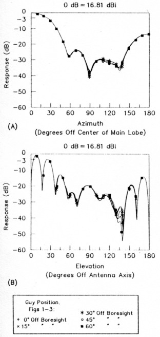
Fig 1 - Modeled patterns for the upper Yagi (height, 109 feet). The horizontal pattern (A) shows very little disturbance; the vertical pattern (B) shows trivial change in the back-lobe structure. The main lobe (at about 9°) is not disturbed at all. (patterns modeled with NEC at 14.2 MHz, over ground with a dielectric constant of 10 and a conductivity of 13 millisiemens per meter)
Figs 2A and 2B show patterns for the lower Yagi. The back-lobe structure in Fig 2A indicates approximately a 4- to 5-dB variation as the antenna rotates. The higher-angle nulls in Fig 2B appear to vary over 20 dB, but all of these variations occur at attenuations greater than 25 dB. (In the real world, such deep nulls are unrealizable because of ground variations.) Although this pattern variation may be intolerable to purists, most contesters and DXers would find it inconsequential.
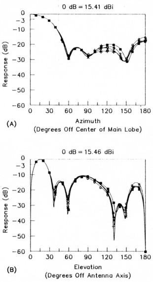
Fig 2 - Modeled horizontal (A) and vertical (B) patterns for the lower Yagi (height, 54 feet) show that the practical effect of continuous, conductive guys is slight. Although the higher-angle nulls in B appear to vary over 20 dB, all of these variations occur at attenuations of 25 dB or greater. Most contesters and DXers would find these effects inconsequential.
Figs 3A and 3B show patterns for the two Yagis driven in phase. As with the previous plots, very little change occurs in the horizontal plane. Some variation does occur at higher elevation angles in the vertical plane, however. As in the previous plots, the guys minimally change the forward main lobe.
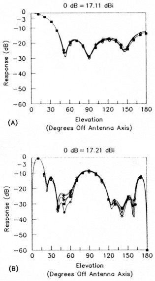
Fig 3 - The effect of continuous, conductive guying on the two Yagis driven in phase. As with the previous plots, very little change occurs in the horizontal plane; some variation does occur, however, at higher elevation angles in the vertical plane. The main lobe changes minimally in both planes.
Fig 4 plots the stacked Yagis' pattern in the total absence of guys (best case) overlaid with the pattern that results when boresight (0°) guys are present (worst case). Except for the second forward lobe at approximately 30°, all of the variations occur at attenuations of 20 dB or greater.
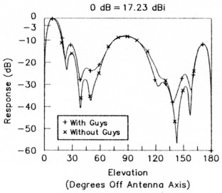
Fig 4 - The stacked Yagis' pattern in the total absence of guys (best case) overlaid with the pattern that results with boresight (0°) guys present (worst case). Except for the secondary forward lobe at approximately 30°, all of the variations occur at attenuation levels greater than 20 dB.
Although 1 do not present the evidence graphically, guys directly below the antenna affect the antenna much more than guys directly in front of the antenna. This is so because a Yagi's feed-point impedance changes rapidly as its boom approaches the guy attachment point on the tower. The higher the antenna's feed-point impedance, the wider its SWR bandwidth and the higher its efficiency. NEC runs using several different boom-to-guy separations indicate that a separation of at least I foot is mandatory at 14 MHz; 3 to 5 feet is preferable. 1 have observed that guy-wire proximity affects Yagis with low feed-point impedances, such as 10 to 15 L , much more than Yagis with impedances of 20 to 35 S2.
Lower-Frequency Antennas
How might continuous, conductive guys affect the pattern of a half-wave sloper (a very popular low-band DX antenna)? I modeled a sloping, half-wave, 75-meter dipole extending, at a 60° angle, from near the top of the 109-foot tower to near the ground. The dipole bisects two of the guy-wire sets. Fig 5A shows the dipole's horizontal-plane patterns (derived at an elevation angle of 20°) with guys (+) and without guys (x). Interestingly, in this specific case, the guy wires actually increase the sloper's gain in the desired direction by over 2 dB! In addition, they also enhance its front-to-back ratio. Fig 5B shows the sloper's vertical-plane patterns, which reflect the same gain differences as Fig 5A.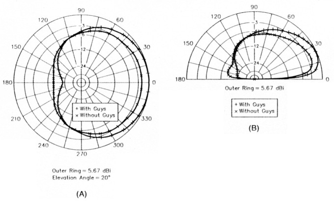
Fig 5 - Continuous, conductive guys slightly enhance the forward-lobe performance of a 75-meter sloper modeled as extending, at a 60° slope, from near the top of the 109-foot tower to near the ground. The antenna's horizontal patterns appear at A; vertical patterns, at B. (patterns modeled with NEC at 3.85 MHz, over ground with a dielectric constant of 10 and a conductivity of 13 millisiemens per meter)
Conclusions
Continuous, conductive guy wires do disturb the patterns of antennas mounted on towers. But unless you're a purist in pursuit of unrealistically clean side lobes, these effects are of no practical importance.
Antennas mounted at the top of a tower (Figs 1A and 1B) show very little effect from guy wires attached several feet below the boom.(3)
Continuous, conductive guy wires may actually enhance the pattern of a low-band wire antenna positioned between them!(4)
As the costs of good-quality insulators. guy-wire preforms (dead ends) and application-specific nonconductive guy cables increase, continuous, conductive guys, installed without insulators, may he a viable guying solution. I hope that this analysis may convince future tower constructors to consider this alternative.
Notes
- NEC is an acronym for Numerical Electromagnetics Code, developed by Lawrence Livermore National Laboratory.
- All wires use segment lengths of 0.1 wavelength or less. For those readers with access to the NEC program, the input and output files are available from me upon receipt of a self-addressed, stamped disk mailer containing a PC/MS-DOS-formatted 1.44-Mbyte, 3.5-inch floppy disk.
- Use as much boom-to-guy-wire separation as is practical to allow side-mount rotation of lower antennas. I recommend a minimum separation of 1 ft at 14.MHz; a separation of several feet is more desirable.
- This applies to this specific case. It's possible that other tower/guy configurations may produce different results.
K4VX, Lew Gordon.