Inside the grounded-grid linear amplifier
Operating a linear amplifier is a pretty simple matter. But the technical details of what happens inside amplifier tubes and impedance-matching networks can be mysterious. Let's unravel those mysteries.
To many Amateur Radio operators. To linear amplifier operating characteristics are mysterious. To help you better understand amplifier operation. I'll discuss the factors that determine the optimum anode (plate) load resistance and the functions of the RF output network. using a grounded-grid linear amplifier as an example. I'll also discuss some modern concepts for tuning and loading adjustment.
Ham stations have gravitated toward the use of a 100-watt-class transceiver followed by a grounded-grid linear amplifier. Grounded-grid amplifier operation is a bit more complex than grid-driven operation because of the effects that "fed-through" drive power cause in the input circuit. Tube operation is easiest analyzed with the aid of an "idealized" set of tube curves. These curves. shown in Fig 1. roughly approximate those of the Eimac 3-500Z. The anode-current lines are spaced so that there is no odd-order inter-modulation distortion.(1) In this tube, the minimum idling current for distortion-free operation is 0.1 A. The curves are drawn so that zero bias is required for a dc anode potential of 3 kV. The left ends of the lines stop approximately where flat-topping and excessive grid current occur. The use of these idealized curves simplifies calculations and makes understanding the fundamental principles of operation a bit easier.
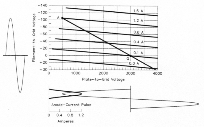
Fig 1 - Idealized anode-current characteristic curves for a tube roughly the size of an Eimac 3-500Z. The input-voltage waveform appears at the left side of the graph; anode current and voltage waveforms are shown below it. The heavy line originating at point A and traveling through point Q is called the load line.
The horizontal scale represents the instantaneous anode-to-grid voltage. The vertical scale represents the filament-to-grid voltage. Note that the values are relative to the voltage on the grid, which is zero in this case. The filament is driven negative (upward on the diagram) to increase anode current. The sine wave to the left of the grid represents the filament-to-grid RF drive voltage. Below the graph. centered at 3 kV. is a sine wave representing the RF anode voltage. These two sine waves are in phase when the anode circuit is resonant.
The anode load line
The heavy line extending from point A through point Q and into the current cutoff region is called the load line. The locations of points A and Q determine tube operation. Point Q represents the zero-signal or idling point; point A determines operation at maximum linear PEP output. This point should be at the edge of the linear range as indicated by the left ends of the current lines. It should also end at a current value that results in the desired dc anode current. RF power output and anode dissipation.
Input and output sine-wave RF voltages are assumed. (RF circuits with sufficient Q maintain nearly sine-wave voltages in real amplifiers.) Also, the voltages are assumed to be in phase. since the load line is elliptical when the anode circuit is out of resonance. Out-of-resonance operation causes reduced power output and efficiency.
With these curves, we can calculate the amplifier's specific operating characteristics based on these givens:
EB = 3000 V (dc anode potential)
ip = 1.2 A (peak anode current read at point A)
ek = 105 V (peak input voltage read at point A)
ep = 2500 V (peak RF anode voltage [3000-500])
IQ = 0.1 A (idling anode current)
These basic tube-operating characteristic calculations represent a single-tone signal at maximum PEP output in class-B operation:
(filament-to-grid input-load resistance)(3)
The anode-current calculation is actually for class-B operation, which would exist if the 0.1-A anode-current line represented zero current instead. The curves represent the real-world case of class AB, however, so the actual dc anode current is slightly higher.
The anode-current pulse shape is shown in the lower left part of Fig 1. Note that the edges of the pulse are flared slightly. The difference between this curve and a true half-sine-wave causes a slight increase in dc anode current. Using a computer to integrate this pulse shows that the dc anode current is actually 0.389 A - 7 mA more than the 0.382 A calculated above. Anode dissipation is also higher (by 0.007 A x 3000 V or 21W), and anode efficiency is reduced to 61.6%. The simple formulas get us close to the correct values, however.
The amount of anode dissipation with zero signal has only a small effect on the anode dissipation at maximum PEP output, although it contributes most of the anode dissipation over fairly long time periods with normal speech signals, because the average signal level is quite low.
Effect of moving Point a - tuning, loading and drive
The effect of moving point A can be determined from Fig 1. Moving it upward exceeds the tube's anode current and/or anode dissipation ratings. A downward shift reduces power output. A leftward move enters the flat-topping distortion region and a shift to the right reduces power output and efficiency. Point A is moved up and down in practice by adjusting the drive level, and is moved right or left by adjusting the loading control (which, as noted earlier must be followed by retuning for resonance).
Tube anode resistance
The effective internal resistance. RS of the amplifier is determined by the tube's anode resistance and the effective source resistance of the driver (as seen across the tube's grid-to-filament connection).
The tube's anode resistance, R. is determined by the slope of the anode-current lines. In Fig 1, find the intersection of 1.5 kV and -40 V, which falls on the 0.4-A anode-current line. Now extend the 0.8 A line to the right until it intersects an extension of the -40 V grid-voltage line (off the graph). This intersection occurs where the anode potential is 6 kV. Thus. with -40 V input, the anode voltage must be increased by 4.5 kV (6 kV -1.5 kV) to get an anode-current increase of 0.4 A (0.8 A - 0.4 A). The tube's anode resistance is, therefore, 4500/0.4 = 11.25 kΩ in the linear part of the tube's characteristic curves. The tube conducts only the equivalent of half of the time, so the effective Rp per Eq 8, is 2 x (4500/0.4), or 22.5 kΩ.
Inherent RF-current feedback
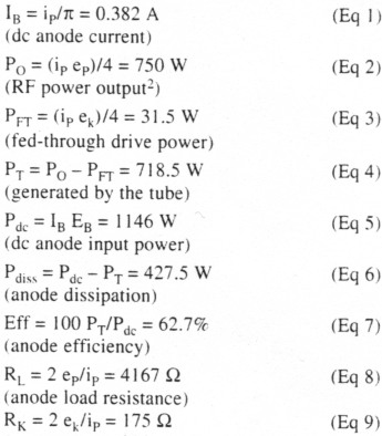
In a grounded-grid amplifier, all of the anode current in the output circuit also flows through the input circuit. Any change in the anode circuit's load resistance (loading) causes a change in the input resistance. Any internal resistance in the driver allows some variation in the drive voltage. The change is small if the driver resistance is low, but if the driver resistance is high, the voltage change can be nearly as large (in percent) as the resistance change. Fig 2 helps clarify this point. On any given frequency, a lossless RF network can be represented by an ideal transformer and a length of transmission line. The first network is the output network of the driver transmitter. and the second is the input circuit of the grounded-grid amplifier. They are connected with a length of transmission line (Fig 2A).
Fig 2 - Equivalent driver circuit (at the fundamental frequency). At A is the output network of the driver and the amplifier input network, connected by a length of transmission line. This network can be treated as three lengths of transmission line with transformers at each end (B). From this, the equivalent generator voltage and line impedance can be derived (C).
In the equivalent circuit (Fig 2B), let's assume that the sum of all line lengths is some multiple of 180°, such as 360°. In this case. the input impedance of the three lines in series is always exactly the same as the load impedance because of the half-wavelength transformer effect. The input transformer steps the coax impedance up to the correct load resistance for the driver's output device(s), and the output transformer steps the coax impedance up to the grounded-grid tube's input resistance (175 Ω for the tube in the earlier example). Next, let's eliminate both transformers by normalizing the generator voltage and line impedance to 175 Ω. as illustrated in Fig 2C.
The internal RS of a driver that uses RF-voltage feedback (such as a Collins KWM-2) is relatively low. Measurements on one transceiver gave approximately 25 Ω relative to a 50-Ω coax impedance, which translates to 87.5 Ω for our example. Broadband, solid-state tranceiver amplifiers probably have RS values closer to 50 Ω. On the other hand, tetrodes with no voltage feedback have quite high RS values - typcally more than 200Ω. In this case, it may be better to use a total phase delay of an odd multiple of 90° to take advantage of the transmission line's impedance-inverting properties.
The amount of effective RF current feedback is determined by the effective source resistance, Rs, at the driver tube's anode terminals. If this source resistance is zero (as in a constant-voltage source), there can be no feedback because variations in anode current cannot affect the drive voltage. On the other hand. if the source resistance is very high (like a constant-current source), any anode-current increase (caused by a loading change or tube nonlinearity), causes the input resistance to decrease, reducing the drive voltage in proportion. The effective feedback would be very high and would completely cancel the tube's anode-current nonlinearity. Intermodulation distortion at the amplifier output would be only that of the driver!
The reason that we don't take advantage of this feedback technique is that nonlinear grid-current circuit loading is usually a much greater cause of distortion. Grid current (plus screen current, in a tetrode) places a nonlinear resistive load across the grid-to-filament circuit. Grid current rises quite steeply as the anode voltage swings down near the grid (or screen) voltage. This nonlinear grid-current loading causes flat-topping and becomes the major cause of intermodulation distortion at large signal levels.
The effect of this nonlinear grid loading can be reduced by providing a low driver source resistance. This is the reason for the special length of coax specified to connect a Collins KWM-2 to a 30S-1 amplifier, for example. This special length, plus the phase delay in the KWM-2 output network and that of the 30S-1's cathode circuit, approximately equals some multiple of 180° on each band. This provides a low source resistance, which reduces the effect of nonlinear screen-current loading in the 30S-1's 4CX1000A or 4CX1500B tetrode, which is cathode-driven and operates in class ABI. The length of connecting coax is therefore important for minimizing inter-modulation distortion. This is why a KWM-2 driving a 30S-1 can produce intermodulation products 41 dB down from PEP output. As stated earlier, solid-state transceivers likely have an RS near 50 Ω. Inter-modulation distortion is acceptable, but not as good as it could be. A properly adjusted ALC circuit should always be used to avoid overdriving the amplifier, thereby keeping distortion acceptable.
Adjusting anode load resistance
As stated earlier, the anode circuit should always be kept in resonance. The load impedance is correct when the desired single-tone dc anode current and dc grid current, or screen current for a tetrode (as given on the tube's data sheet for typical operating conditions), occur at the same time. The drive level must be adjusted along with loading to reach that point.
Tuning and loading detectors
The RF anode voltage is in phase with the RF filament-to-grid voltage when the anode circuit is in resonance. Therefore, a phase discriminator can be used to indicate resonance. The discriminator output can feed a zero-center meter to indicate the direction and magnitude of tuning error. The direction of error is independent of signal amplitude, but, of course, its magnitude depends on the signal amplitude. A linear amplifier can be tuned to resonance during voice transmission using such a device.
A similar approach to loading adjustment uses a detector to monitor the correct ratio of RF anode voltage to RF grid-to-filament voltage. In the example, this ratio is 2500/105 = 23.8. This ratio can be monitored by dividing both voltages down to the same level (such as 5 volts) and using a diode detector to produce a positive voltage from one sample and a negative voltage from the other. When adding the two produces a 0-V output, the loading is properly adjusted. Incorrect loading will show either a positive or negative output voltage, indicating which way the loading should be adjusted. This adjustment can also be made while transmitting. Compared to the traditional method of tuning with a key-down signal, this is a much more friendly way to tune an amplifier!
RF output circuitry
The RF circuitry for transforming the antenna impedance to the correct load resistance (RL) for the tube typically includes the amplifier's output network and a transmission line. Additional circuitry is often employed to match the antenna to the transmission line, and/or a network to match the coax input impedance to the desired 50-Ω load for a broadband, solid-state transceiver. For simplicity, I'll describe a coupling system consisting of a tuned output network and a length of 50-Ω transmission line connected directly to a vertical antenna.
Fig 3 shows the circuit. The vertical antenna is assumed to have an input impedance of 30 -j40Ω, which causes a 3:1 SWR on the transmission line. The transmission line is assumed to have an electrical length of 2½ wavelengths, which results in a coax-input impedance of 30 +j40Ω.

Fig 3 - The amplifier's RF-output network matches the antenna's feed-line input impedance to the amplifier's anode load resistance.
RF output network
The output network is required to perform several functions:
- Transform the input impedance, ra +jxa, to 4167 Ω, which is the anode load resistance in our example. (A practical network must be tunable over the desired frequency range and also over the desired load-matching range, such as 3:1 SWR)
- Provide sufficient input-circuit Q (or circulating energy) to maintain a nearly sinewave voltage across the tube. (The tube generates a pulse of anode current each RF cycle.) A Q of 10 or more is adequate.
- Provide sufficient harmonic attenuation. The second-harmonic content of the anode-current pulses is approximately 7 dB down at maximum output. The transmitter's second-harmonic output should be at least 50 dB down, which a pi-L network can provide with a large margin.
The tuning and loading functions are normally achieved by varying C1 and C2, respectively. Inductors L1 and L2 are preset for each band by switching taps on the coils. C1 is tuned for resonance, assuring that the tube sees a resistive load. C2 is adjusted in small increments (followed by retuning C1) until the correct load resistance is obtained. When the tuning and loading adjustments are completed, the output network transforms the coax input impedance (30 +j40 Ω in our example) to the tube's RL. 4I67 Ω
If we pulled the plug on our linear amplifier after correctly tuning it, we could connect an RF impedance meter from the tube anode to ground and measure an impedance of 4167 Ω. If we looked back into the output network from the coax output terminal (with the amplifier turned on but with no signal applied) we would observe a very high SWR, as previously reported.(4) Of course, this has no effect on the transmitted signal.
Summary
The operating conditions of a grounded-grid linear amplifier are determined by the anode load resistance and drive-voltage amplitude. The anode load resistance determines the slope of the load line. There is practically no relationship between the correct tube load resistance and the effective internal resistance, RS, of the amplifier.
Thanks to Dr T. R. Cuthbert and S. E. Bonney, W5PAQ, for their helpful comments during the preparation of this manuscript.
Notes
- E. W. Pappenfus, W. B. Bruene and E. O. Schoenike, Single Sideband Principles and Circuits (New York: McGraw-Hill, 1964), pp 188-190.
- This equation does not take into account output-network loss.
- Grid current adds input loading and typically reduces RK to approximately 70% of this value.
- W. Bruene, "RF Power Amplifiers and the Conjugate Match," QST, Nov 1991, pp 31-32,35.
W5OLY, Warren Bruene.