Taking the mystery out of diode double-balanced mixers
Here's a look into the workings of a common signal-processing block many modern telecommunication systems couldn't do without.
Double-balanced mixers (DBMs) are common in modern communication and signal-processing systems. They can serve as mixqrs (including image-reject types), modulators (including single- and double-sideband, phase, biphase, and quadrature-phase types) and demodulators, limiters, attenuator switches, phase detectors, and frequency doublers. In some of these applications, they work in conjunction with power dividers/combiners and hybrids.
A DBM type commonly used in Amateur Radio and industry consists of little more than a diode ring and coupling transformers. Radio amateurs have been using such DBMs in homemade and commercial forms for at least 25 years, yet these DBMs' characteristics remain mysterious to some. This article explores these mixers' construction, characteristics and application.
How Diode Double-Balanced Mixers Look and Work
The Basic DBM Circuit
A diode double-balanced mixer (Fig 1) contains two or more unbalanced-to-balanced transformers and a diode ring consisting of 4 x n diodes, where n is the number of diodes in each leg of the ring. Each leg commonly consists of up to four diodes. Input and output ports-commonly named local oscillator (LO), radio frequency (RF) or signal, and intermediate frequency (IF)-connect the DBM to its associated circuitry.
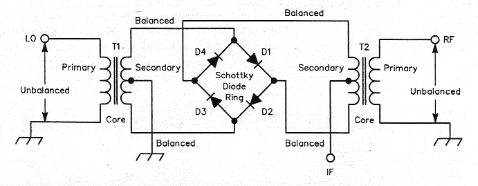
Fig 1- A diode double-balanced mixer consists of two unbalanced-to-balanced transformers and a Schottky-diode ring.
Basic DBM Function
See Fig 1. Applied to the diode ring's D4-D1 and D2-D3 terminals via T1, a 1:4transformer, LO energy forces D1 and D2 into full conduction on each positive half cycle of the LO waveform. D3 and D4 conduct on each negative half cycle. T2, also a 1:4 transformer, applies the RF-port signal to the ring's D1-D2 and D3-D4 terminals. The LO (fLO) switches the RF signal (fRF) to the IF port at the LO frequency, resulting in RF/LO frequency multiplication. The resultant IF-port signal includes two dominant components, fLO+fRF and fLO-fRF, in addition to harmonic products offLO and fRF.
The degree to which a mixer is balanced depends on whether either, neither or both of its input signals (RF and LO) emerge from the IF port along with mixing products. An unbalanced mixer suppresses neither its RF nor its LO; both are present at its IF port. A single-balanced mixer suppresses its RF or LO, but not both. A double-balanced mixer suppresses its RF and LO inputs. Diode and transformer uniformity in the Fig 1 circuit results in equal LO potentials at the center taps of T1 and T2. The LO potential at TI's secondary is zero (ground); therefore, the LO potential at the IF port is zero.
Balance in T2's secondary likewise results in an RF null at the IF port. The RF potential between the IF port and ground is therefore zero.
The Fig 1 circuit normally also affords high RF-LO isolation because its diode switching precludes direct connections between TI and T2. A diode DBM can be used as a current-controlled switch or attenuator by applying dc to its IF port. This causes opposing diodes (D2 and D4, for instance) to conduct to a degree that depends on the current magnitude, connecting T1 to T2.
| Part | Typ Vf @ 1 mA (mV) | Max Ci @ 0 Volts (pF) | Max Vo @ 5 mA (mV) | Typ Rs @ 5 mA (Ohms) | Approx max operating frequency (GHZ) |
|---|---|---|---|---|---|
| MP2400 | 290 | 0.10 | 15 | 20 | 35 |
| MP2401 | 290 | 0.10 | 15 | 20 | 40 |
| MP2402 | 290 | 0.15 | 15 | 20 | 26 |
| MP2403 | 290 | 0.20 | 15 | 20 | 18 |
| MP2407 | 270 | 0.20 | 15 | 15 | 18 |
| MP2410 | 240 | 0.25 | 15 | 10 | 18 |
| MP2412 | 240 | 0.30 | 15 | 10 | 12 |
| MP2414 | 240 | 0.45 | 15 | 10 | 8 |
| MP2417 | 220 | 0.55 | 15 | 8 | 6 |
| MP2418 | 220 | 0.60 | 1 | 8 | 4 |
Courtesy of M-Pulse Microwave
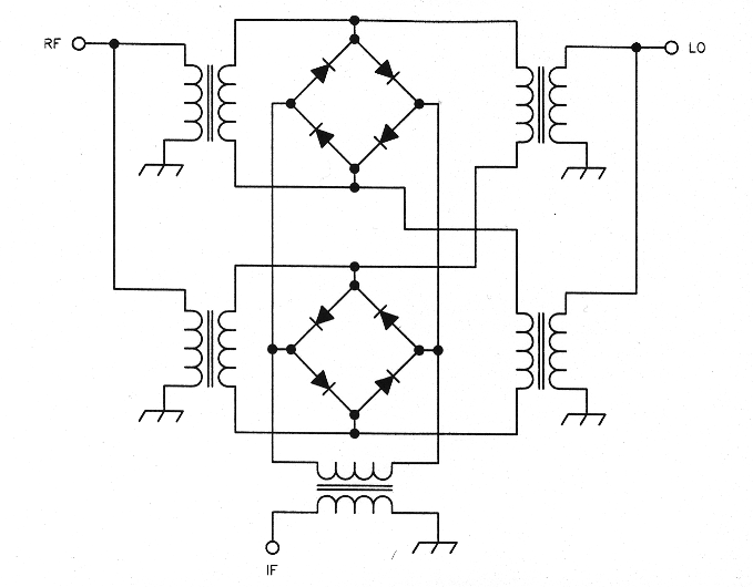
Fig 2- Five transmission-line transformers and two Schottky-quad rings form this double double-balanced mixer (DDBM). Such designs can provide lower distortion, better signal-handling capability and higher interport isolation than single-ring designs.
One extension of the single-diode-ring DBM is a double double-balanced mixer (DDBM) with high dynamic range and larger signal-handling capability than a single-ring design. Fig 2 diagrams such a DDBM, which uses transmission-line transformers and two diode rings. This type of mixer has a higher 1-dB compression point (usually 3 to 4 dB lower than the LO drive) than a DBM. Low distortion is a typical characteristic of DDBMs. Depending on the ferrite core material used, frequencies as low as a few hundred hertz and as high as a few gigahertz can be covered.
Diode Double-Balanced-Mixer Components
Commercially manufactured diode DBMs generally consist of: (A) a support base on which the unit is constructed; (B) a diode ring; (C) two or more ferrite-core transformers wound with transmission lines, two or three twisted-pair wires, or a combination of both; (D) encapsulating material; and (E) an enclosure.
Diodes
Hot-carrier (Schottky) diodes are the devices of choice for diode-DBM rings. The forward voltage drop, Vf, across each diode in st a ring determines the mixer's optimum local-oscillator drive level. Depending on the forward voltage drop of each of its diodes and the number of diodes in each ring leg, a diode DBM may be categorized as a 0, +3, +7, +10, +13, +17, +23 or +27 dBm-level mixer.
Schottky diodes are characterized by loss and contact resistance (R), junction capacitance (C), and forward voltage drop (V) at a known current, typically 1 mA or 10 mA. The lower the diode-to-diode Vf difference in millivolts, the better the diode match at dc. (Some earlier diode DBM designs used diodes in series with a parallel resistor/ capacitor combination for automatic biasing.) Better diode matching (in Vf and Ci) results in higher isolation among the ports. Diodes capable of operating at higher frequencies have lower junction capacitance and lower parasitic inductance. Fig 3 shows the equivalent circuit for Schottky diodes of three package types.
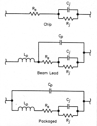
Fig 3-Its semiconductive properties aside, a Schottky diode can be represented as a network consisting of resistance, capacitance and/or inductance. Of these, the junction capacitance (C1) plays an especially critical role in a double-balanced mixer's high-end response. (R junction resistance, RS = contact resistance, LP = parasitic inductance and Cp = parasitic capacitance.)
Manufacturers of diodes suitable for DBMs characterize their diodes as low-barrier, medium-barrier, high-barrier and very-high-barrier (usually two or more diodes in each leg), with typical Vf values of 220 mV, 350 mV, 600 mV and 1 V or more, respectively. Fig 4 shows a typical current-voltage (I-V) characteristic for a low-barrier Schottky quad capable of operating up to 4 GHz. Note that as current through the diodes increases, the Vf differenceamong the ring's diodes also increases, affecting the balance.
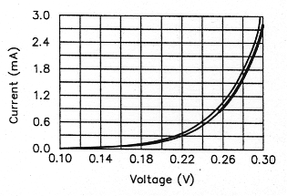
Fig 4- Current-voltage (I-V) characteristic for Schottky diode quad, showing worst-case voltage imbalance (the spread between the two curves) among the four diodes.
At higher frequencies, diode packaging becomes critical and expensive. As the frequency of operation increases, the effect of junction capacitance and package capacitance cannot be ignored. Part or all of the capacitance can be compensated at the mixer's highest operating frequency by properly designing the unbalanced-to-balanced transformers. The transformer inductance and diode junction capacitance form a low-pass network with its cutoff frequency higher than the frequency of operation. Compensated in this way, diodes with a junction capacitance of 0.2 pF can be used up to 8 to 10 GHz.
Table 1 shows typical parameters for Schottky ring diodes.
Transformers
From the DBM schematic shown in Fig 1, it is clear that the LO and RF transformers are unbalanced on the input side and balanced on the diode side. The diode ends of the balanced ports are 180° out of phase throughout the frequency range of interest. This property causes signal cancellations that result in higher port-to-port isolation. Fig 5 plots LO-RF and LO-IF isolation versus frequency for Synergy Microwave's CLP-4A3 DBM. Isolations on the order of 70 dB occur at the lower end of the band as a direct result of the balance among the four diode-ring legs and the RF phasing of the balanced ports.
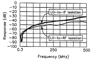
Fig 5- A diode DBM's port-to-port isolation depends on how well its diodes match and how well its transformers are balanced. This graph shows LO-IF and LO-RF isolation versus frequency for a Synergy Microwave CLP-4A3 mixer.
Transformer efficiency plays an important role in determining a mixer's conversion loss and drive-level requirement. Core loss, copper loss and impedance mismatch all contribute to transformer losses.
Ferrite in toroidal, bead, balun (multihole), or rod form can serve as DBM transformer cores. Balun and toroidal cores are most commonly used, and are available from TDK, Siemens, Ferroxcube, Krystinel and other vendors.
Before selecting a material type (or magnetic permeability, µ), its temperature coefficient and Curie temperature (the temperature at which the core loses its magnetic properties) must be considered. In some cases, it may change drastically across the desired temperature range; this would cause a transformer's frequency response to shift with temperature. Once a suitable core material and form have been selected, the transformer's size and frequency requirements determine the necessary core size.
For a given core shape and size, the number of turns, wire size, and the number of twists determine transformer performance. Wire placement also plays an important role. The wires' insulation thickness determines the isolation between the wire and the core. Care must be taken to ensure that the insulation does not break during tight winding or due to mishandling. Sharp-edged cores should be avoided; these can break insulation and nick wires. Subjected to repeated hot-cold flexing, nicked wires may fail open.
RF transformers combine lumped and distributed capacitance and inductance. The interwinding capacitance and characteristic impedance of a transformer's twisted wires sets the transformer's high-frequency response. The optimum number of turns necessary to achieve best performance at the upper end of a transformer's operating range differs with the core type used. The core's t and size, and the number of winding turns, determine the transformer's lower frequency limit. Covering a specific frequency range requires a compromise in the number of turns used with a given core. Increasing a transformer's core size and number of turns improves its low-frequency response. Many times, cores may be stacked to meet low-frequency performance specs.
Inexpensive mixers operating up to 2 GHz most commonly use twisted trifilar (three-wire) windings made of a wire size between #36 and #32. The number of twists per unit length of wire determines a winding's characteristic impedance. Twisted wires are analogous to transmission lines and can be analyzed in terms of distributed interwinding capacitance. Decreasing the number of twists lowers the interwinding capacitance and increases the frequency of operation. If the wists per inch are fewer than four, handling becomes difficult.
The transmission-line effect predominatesat the higher end of a transformer's frequency range. If two impedances, Z1 and Z2, need to be matched through a transmission line of characteristic impedance, Z0 then
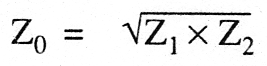
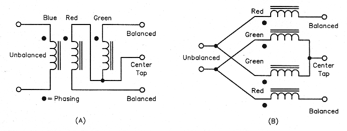
Fig 6-Transformers for DBMs: three-wire (A), and transmission-line (B).
Fig 6 shows two types of transformers using twisted wires: (a) a three-wire type in which the primary winding is isolated from the secondary winding with a center tap, and (b) a two-wire (transmission-line) type in which two sets of transmission lines are interconnected to form a center tap at the secondary with a direct connection between primary and secondary. The primary-secondary turns ratio determines the impedance match, as shown in Eq 1. The properties of these two transformer types can be summarized as follows:
1. By virtue of its construction, the three-wire transformer is more unsymmetrical at higher frequencies than the transmission-line type.
2. The transformers' lower cutoff frequency (fL) is determined by the equation
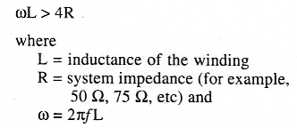
3. The transmission-line transformer's upper cutoff frequency (fH) is determined by the highest frequency at which its wires' twists (that is, the coupling between them) allow it to function as a transmission line of the proper characteristic impedance.
4. Transformers convert one impedance, Z1 (primary) to another, Z2 (secondary) according to the relationship
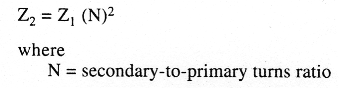
Within certain limits, if Z1 is varied, Z2 also varies to a new value multiplied by N2. Thus, a mixer designed for a 50-Ω system may work in a 75-Ω system with minor modifications.
Support Base
The base serves as a support for all of the mixer's components and connecting leads while providing whatever mechanical strength the application requires. The base can be made of plastic (or any other insulator) or metal.
Plastic packages are commonly used in cost-sensitive systems. Plastic packages are inexpensive, lightweight, can be easily molded, and can be formed into complicated shapes. Offsetting these advantages, they are unsuitable for very high frequency operation, susceptible to cracking, easily destroyed by chemicals, non-hermetic, poorly resistant to heat and mechanically weak. Further, the tendency of plastic packages to warp and crack limits their maximum size.
Metal packages can be made from a variety of metals and alloys, such as brass, copper, cold rolled steel, Kovar and aluminum. (Different applications often require that specific platings be applied to these base metals.) Glass-to-metal or ceramic-to-metal sealstransfer the mixer-port leads through the package. Metal mixer packages can be hermetically sealed. Hermetic packages are suitable for harsh environments and are extensively used in military applications.
Another advantage of metal packaging is that it serves as a conductive (and therefore shielding) plane that resists electromagnetic interference (EMI) and radio-frequency interference (RH). Unlike plastics, metal packages do not warp, and need not be restricted in size for this reason.
Encapsulating Material
Commercial mixers are often encapsulated-potted-to be sure that their components cannot be dislodged during vibration, impact, thermal stress and so on. Many different encapsulants are available on the market; however, some of them crack when heated. Each of these products is unique in the sense of hardness, weight, dielectric constant, dielectric loss, thermal conductivity, elasticity, adhesion to different surfaces, chemical resistance, fungus resistance, brittleness and so on, so they must be evaluated carefully before specification. Some encapsulants can act as a heat sink to remove component heat.
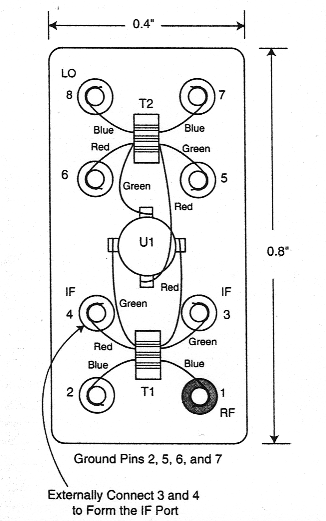
Fig 7 - How a typical commercial DBM is wired. The use of different wire colors for the transformers' various windings speeds assembly and minimizes error. U1, a Schottky-diode quad, contains D1-D4 of Fig 1.
Diode DBMs in Practice
Fig 7 shows the wiring of a typical DBM that uses toroidal cores. The wires are wrapped around the package pins and diode leads, and then soldered. In this unit, the primary winding of the LO transformer connects across pins 7 and 8; the RF-transformer primary, across pins 1 and 2. The pin pairs 3-4and 5-6 are connected externally to form the transformers' secondary center taps, one of which (5-6, that of the LO transformer) connects to a common ground point while the other (3-4, that of the RF transformer) serves as the IF port.
The DBM shown in Fig 7 has a dc-coupled IF port. If necessary, this DBM can be operated at a particular polarity (positive or negative) by appropriately connecting the LO, RF, IF and common ground points.
DBMs and DDBMs are available in plug-in and surface-mount packages. Plug-in packages commonly come in metal cans measuring (for eight-pin packages) 0.8 inch (length) x 0.4 inch (width) or (for eight- or four-pin packages) 0.5 inch x 0.25 inch, with heights ranging from 0.25 to 0.4 inch. Flat-packs measuring 0.51 x 0.385 x 0.15 inch are metal packages, classified as surface-mount types. Synergy's surface-mount DBMs and DDBMs are available in leaded and nonleaded versions, and come in two configurations: ceramic base, with a ceramic or plastic cover, and glass-epoxy base, with a plastic cover. The Synergy surface-mount line includes a patented hermetic package with excellent EMURFI suppression.
DBM Specification
The typical parameters involved in selecting a diode DBM are: (A) conversion loss and its flatness (ripple) across the required IF bandwidth; (B) variation of conversion loss with RF frequency; (C) variation of conversion loss with LO drive, (D) 1-dB compression point; (E) LO-RF, LO-IF and RF-IF isolation; (F) intermodulation products; (G) noise figure (usually within 1 dB of conversion loss); (H) port SWR; and (I) dc offset, which is directly related to isolation among the RF, LO and IF ports.
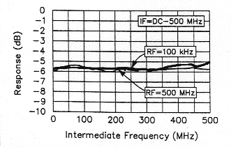
Fig 8-Conversion loss versus frequency for a typical diode DBM. The heavier curve shows the loss for RF = 100 kHz; the lighter, for RF = 500 MHz. The LO drive level is +7 dBm.
Fig 8 shows a plot of conversion loss versus intermediate frequency in a typical DBM. The curves show conversion loss for two fixed RF-port signals, one at 100 kHz and the another at 500 MHz, while varying the LO frequency from 100 kHz to 500 MHz. To give some additional insight, Fig 9 plots a diode DDBM's simulated intermodulation distortion. Note that the RF input is -20 dBm and the IF output (the frequency difference between the RF and LO signals) is -25 dBm, implying a conversion loss of 5 dB. This figure also applies to the sum of both signals (RF + LO).
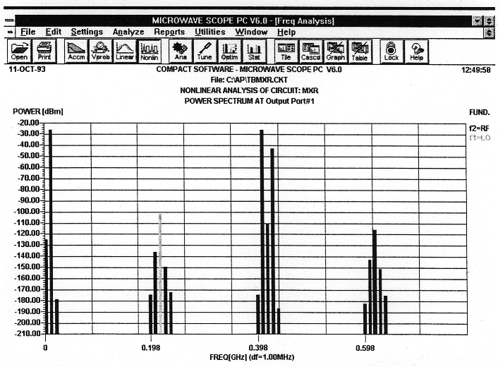
Fig 9-Simulated diode-DBM intermodulation distortion. Note that the desired output products (the highest two products, RF-LO and RF+LO) emerge at a level 5 dB below the mixer's RF input (-20 dBm). This indicates a mixer conversion loss of 5 dB. (Microwave SCOPE simulation)
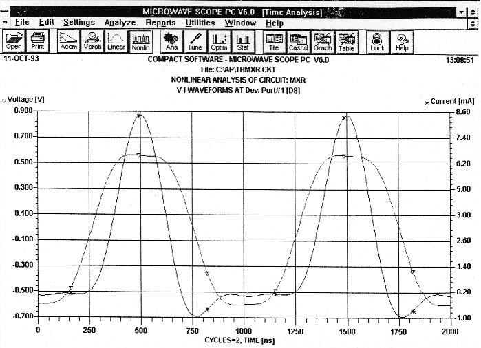
Fig 10-Sampled current and voltage waveforms across one of the diodes in a DDBM ring reflect the mixer's nonlinear action. (Microwave SCOPE simulation)
Fig 10 shows the waveforms across one of the diodes in a DDBM ring. Note the signal distortion, which indicates high harmonic content. Despite this distortion, the mixer's output is relatively clean because of the cancellation due to balance in the mixer's diodes and transformers.
Fig 11 shows the diode's phase plane. It indicates the RF swing across the diode based on the energy stored in the diode's capacitance.
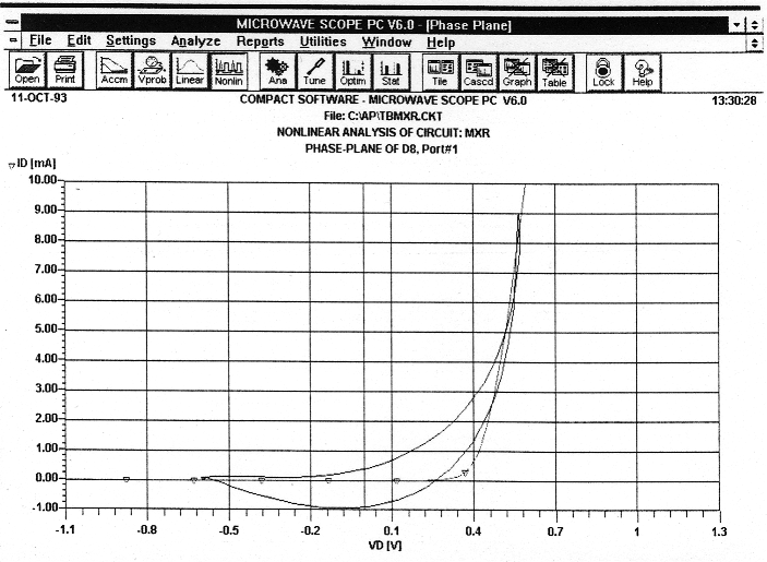
Fig 11-Phase plane of the one of the diodes in a DDBM ring. The curves show the diode's dc and dynamic load lines across the operating range, and reflect the effect of energy storage in the diode's junction capacitance. (Microwave SCOPE simulation)
Conclusion
I hope that this article sheds some light on the workings of diode double-balanced mixers, which commonly serve as signal-processing building blocks in Amateur Radio and industry. Whether you build your own DBMs or buy them ready-made, their design, specifications and construction need not be mysterious.
Acknowledgments
I thank the following individuals for their contributions to this project, without whose assistance this effort would have been unsuccessful: Dr. Ulrich L. Rohde-invaluable advice and counsel; Mike Vogas-technical expertise and creation of the drawings; and Merle L. Cioban-Chandler--word-processing support.
By Shankar Joshi, Chief Engineer Synergy Microwave