Measuring and compensating oscillator frequency drift
How stable is the VFO in your rig? A frequency counter, a simple environmental chamber, and a home-built electronic thermometer can allow you to measure and even compensate the drift in your oscillators.
An oscillator's stability characterizes n its relative freedom from undesired frequency change. Many factors can cause unwanted frequency shift. Variations in loading (termination) can cause pulling. Altering the oscillator power supply voltage can cause pushing. Circuit noise can modulate an oscillator, leading to phase-noise sidebands.
The most common form of oscillator instability, however, is that related to temperature. The inductors, capacitors, crystals, and/ or transmission lines that determine oscillator frequency have values that depend upon temperature. Temperature changes arise either from internal heating, which causes warm-up drift, or from changes in the environment surrounding the circuitry. Both of these are called thermal drift.
Variable frequency oscillator (VFO) drift has always been a topic of vital concern to the radio amateur. Articles on the subject abound, with each author presenting his or her own recipe for achieving oscillator stability. Some of this lore is wellfounded - that is, based on careful observation and sound thinking, and correspondence between the two. Other contributions depart from science. The collective result is confusing, if not chaotic. Believing the lore may cause us to build ill-conceived circuits while we ignore others that might offer wonderful stability.
VFO design is an ever-evolving pursuit. Internal heat generation was the major problem we fought with vacuum-tube oscillators. Although less severe, these thermal effects persist with solid-state oscillators. A more recent difficulty adds further complication: Some critical VFO components are no longer commercially available. Stable fixed-value capacitors and high-quality variable capaci tors are relatively difficult to find. (Some fixed-ceramic capacitors advertised as having an NP0 temperature characteristic do not really qualify. More later on this.) The smooth, double-bearing "variables" used in our vintage rigs have been largely replaced by smaller, but more rugged and robust tuning diodes. The diodes are easy to use and offer wonderful mechanical stability, but they also tend to have terrible temperature characteristics and be lower-Q than the mechanical variables they replace. They can also generate noise.
Thermal stability problems can be solved through careful measurements. The requisite tools for oscillator measurement include a frequency counter and a simple environmental chamber with a controlled, measured temperature. An initial measurement (at power up) determines the oscillator's "cold" output frequency. Further measurements at the same chamber temperature quantify what warm-up drift occurs. Heating the chamber then adds the factor of rising ambient temperature. Further temperature and frequency measurements then characterize the oscillator's thermal stability.
Many experimenters already own frequency counters, so this article will describe a simple thermal chamber I built for oscillator evaluation. I'll also present several methods for temperature measurement - a vital part of the process - and show how to use the counter, temperature chamber and thermometer for oscillator evaluation.
Once the measurement tools are in place, the details of temperature compensation can be explored. I'll discuss some of the things that cause drift in oscillators, and how components are specified for temperature stability. I'll inen present some examples that illustrate the compensation process.
Temperature measurement
The ambient temperature in a ham shack is usually around 20 degrees Celsius (°C). A reasonably useful ham environmental chamber would produce temperatures from -20 to +70 °C. The chamber I'll describe is less ideal; it operates only at room temperatures and above. It is still nonetheless useful to be able to measure temperatures on either side of 20 °C.
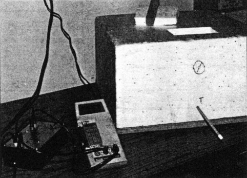
A mercury thermometer, available from a chemical supply house, serves as an easyto-use and traditional solution. For some experiments, I've used a Curtin Matheson Scientific Inc type CM-8 (catalog #248422), which covers -20 to +150 °C. A hole in the chamber passes the thermometer. Most of the thermometer remains outside the chamber; its mercury bulb enters the chamber at the same height above the bottom of the chamber as the circuit under test.
A photographic shop may also carry a thermometer you can use: Photo thermometers, typically priced around $20, operate over a temperature range that includes most of the one we need. Some home thermometers may even work, although many lack useful resolution. The restricted range of medical thermometers makes them unsuitable for our purposes.
If you already have a digital multimeter (DMM), you can cheaply and easily build the ultimate solution, an electronic digital thermometer. (If you're an avid experimenter who doesn't have a DMM, put one on your "wish list.") Two possible circuits (Fig 1) use National Semiconductor's LM3911 IC temperature sensor. The simpler circuit, Fig 1A, provides a readout in kelvins. The LM3911 has an output of 10 mV/°C, so this circuit provides 0.1-°C resolution when used with a DVM capable of 1-mV resolution at the 3-V level. Fig 1 B shows a version with direct readout in degrees Celsius.
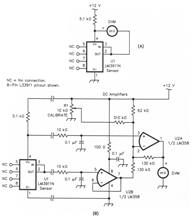
Fig 1 - Two solid-state thermometers based on the LM3911 temperature sensor IC, one with readout in kelvins (A) and another (B) with readout in degrees Celsius. The circuit's fixed resistors are ¼-watt carbon-film; the capacitors, general-purpose ceramic. R1, CALIBRATE, is a trimmer potentiometer.
The TO-46 metal-can LM3911 I used in my thermometer needed a small heat sink to guarantee accuracy. Without it, self-heating in the sensor IC can generate errors of several degrees, even with the IC dissipating only 5 mW. An 8-pin plastic LM3911 (LM3911N) is available from Digi-Key for about $2. This plastic IC can be epoxied to a small, junk-box heat sink. Alternatively, the LM3911N may provide accurate results without a heat sink if its unused pins (5, 6, 7, and 8) are soldered to the surface where ternperature is being measured. Some experiments may be required here.
I built the Fig 1B circuit in two sections. A small scrap of PC-board material carrying the LM3911 resides in the temperature chamber. A box away from the chamber contains the offset amplifier. There is nothing critical about the offset circuit and any construction form is suitable. R1, the CALIBRATE pot, should afford high resolution.
The electronic thermometer can be calibrated at room temperature using a chemical thermometer as a standard. Absolute temperature accuracy is not especially important for this application. What's more important is the ability to measure temperature changes with accuracy and repeatability.
The chamber
The thermal chamber (see title photo) can be as simple or as elaborate as you would like it to be. The oven described here emphasizes simplicity, but it still provides a great deal of information.
A thermal chamber consists of a source of heat and an enclosure to spatially confine the heat. A 60-watt light bulb serves as the heat source. The only control is a toggle switch. The bulb resides in a ceramic socket mounted on a piece of fiberboard about 16 inches square (see photo this page). Another piece of fiberboard, placed vertically between the light bulb and the part of the chamber containing the circuit under test, prevents direct bulb radiation from reaching the circuit under test.
The chamber itself is a 9-inch deep Styrofoam box originally used as a shipping container for tropical fish. (At a supermarket, I located a suitable substitute box in the form of a Styrofoam picnic cooler. A usable substitute could be fabricated from plywood, or even cardboard.) The box is inverted and placed over the fiberboard base. Wood strips on the base locate the Styrofoam, simplifying the box's quick removal and replacement when inserting test circuits.
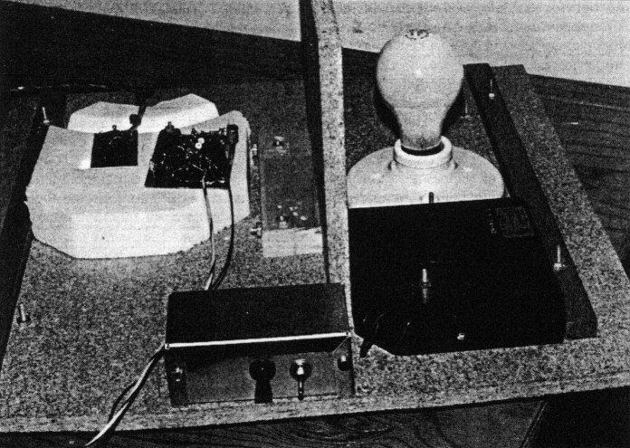
Inside the chamber, a vertical partition separates the incandescent-lamp heat source from the circuit under test. The switch box controls the lamp and exhaust fan.
The box confines the light-bulb heat through the excellent insulation properties of Styrofoam. Lining the inside surface with aluminum foil would further improve the chamber's thermal performance by providing reflection as a second isolation mechanism. The metal would, however, act as a thermal load and slow the rate at which the chamber temperature can be changed.
My chamber also contains a small fan configured to exchange room and chamber air. This allows quick cooling of the chamber air to ambient temperature. Air exits through a small outlet hole in the Styrofoam. A Styrofoam plug normally closes a hole in the top of the box; removing the plug allows room air to enter when cooling is desired. (The cooling fan is a convenience and is not essential. The chamber would be effective without it.)
Another useful chamber refinement would be a small internal fan to circulate the air within the chamber. Such a fan must be carefully mounted to avoid inducing mechanical vibrations that might compromise oscillator performance.
Thermometer measurements indicated that the chamber temperature is higher at the top when the heat source is on. It's therefore useful to put the circuit under study on a small pedestal made from a piece of Styrofoam packing material. The thermometer should be close to, and at the same height as, the circuit under study.
Testing and using the chamber
My initial experiments with the chamber dealt with thermometer calibration. I began oscillator testing only after confirming proper operation of the chamber and thermometer.
The first oscillator tested was a 7-MHz VFO from a portable QRP transceiver. This circuit, a design based on earlier lore that promoted Micrometals SF (-6 designation) toroid inductors and NPO capacitors,(1)(2) was built in a small aluminum box. Although drift has certainly been observed with this circuit, it has been tolerated. The transceiver has seen considerable use over a decade-long period from locations as thermally diverse as sun-drenched ocean beaches and mountaintops to snow caves in winter.
I placed the entire VFO box in the chamber with the electronic thermometer in close proximity. Cabling carried signal and power connections for the thermometer and circuit under test. After placing the Styrofoam box over the chamber base, I applied power to the VFO and measured its frequency with the counter. The frequency dropped by about 150 Hz over the first 10 minutes of operation; this is the warm-up drift. A slight increase in chamber temperature accompanied oscillator warm-up. Fig 2 shows the experiment's frequency and temperature versus time for this period.
Ten minutes after powering up the VFO, I turned on the chamber heat. As Fig 2 indicates, the temperature immediately began to increase. The accompanying frequency change, however, was not immediate. Only after a couple of minutes of increasing temperature did the VFO frequency begin to drop. The time delay results from the thermal isolation provided by the VFO box.
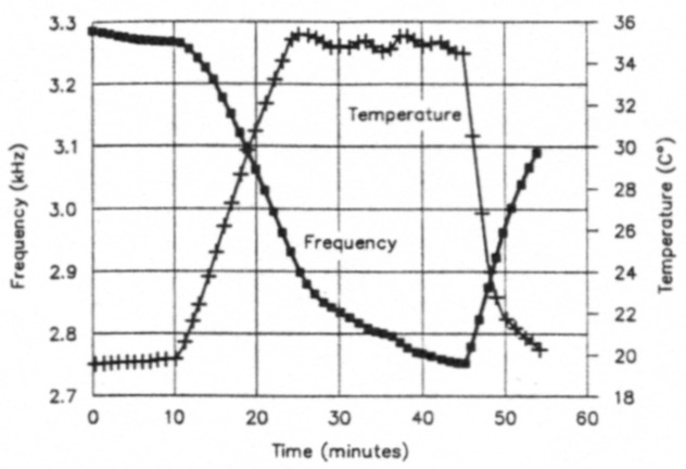
Fig 2 - Results of a drift run made on the Ugly Weekender (JFET Hartley) VFO operating with its enclosure closed.
I kept the heat on until the chamber temperature reached 35 °C - for 24 minutes. Then I cycled the heat on and off in short bursts to maintain a chamber temperature around 35 °C. The VFO's frequency decreased more slowly during this interval, but never reached equilibrium. At 45 minutes into the test, I turned on the fan. The thermal insulation properties of the VFO box again complicated the measurements by slowing the onset of cooling inside the box. Such thermal isolation is very useful; it is a major reason for building a VFO in a separate box!
I removed the VFO from the environmental chamber immediately after obtaining the data for Fig 2. Then I removed the transceiver cover, returned the VFO to the chamber, and repeated the measurements. Fig 3 shows the results on the same time scale used in Fig 2. The VFO was still warm from the previous experiment, so the starting temperature was higher. The warm-up was similar to the earlier one, but when I applied oven heat at 7 minutes into the experiment, the VFO started to change frequency almost immediately. The frequency changed in direct response to changing temperature. Moreover, the frequency was relatively stable as soon as I turned the heat off at 20 minutes. Also, the chamber took less time to reach 35 °C than in the earlier run. Clearly, VFO enclosures should be removed or opened for temperature compensation measurements.
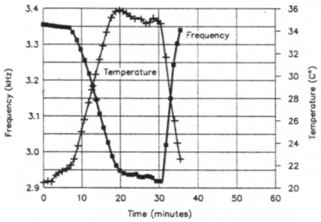
Fig 3 - An Ugly Weekender drift run made with the transceiver's enclosure open. The quicker response of the VFO components to test-chamber temperature changes is clearly evident.
A small circuit board carrying an experimental oscillator should be much more responsive to thermal changes than one in an enclosure. I confirmed this with the design presented in Fig 4. A PNP transistor serves as a Colpitts oscillator. The PNP circuit's collector operates at do ground when powered from a negative-ground supply - convenient when biasing a tuning diode. I used NPO ceramic capacitors for the circuit's three frequency determining elements. The inductor value chosen produced oscillation very close to 7 MHz, the same value as was used earlier. The inductor was wound on an SF toroid, a T-50-6.
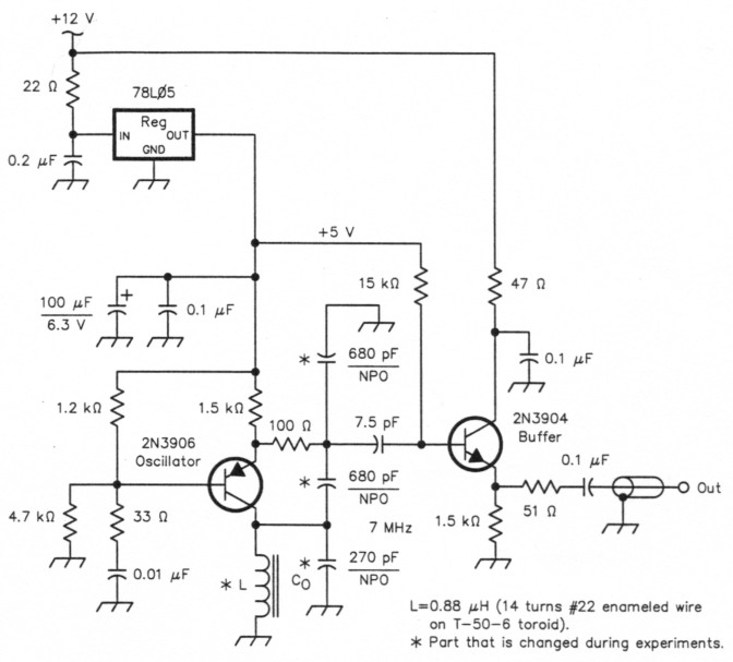
Fig 4 - The 7-MHz bipolar-junction-transistor Colpitts VFO used for temperature-compensation experiments. Its resistors are ¼-watt carbon-composition; all of its nonpolarized capacitors not marked NP0 are general-purpose ceramics.
Fig 5 shows frequency and temperature versus time for this circuit. I turned the oven on at 4 minutes and off at 17 minutes into the test. The oscillator seemed to follow the chamber temperature with virtually no time lag. Additional experiments to higher temperatures showed that the frequency continued to drop as temperature increased to values as high as 50 °C. The run shown in Fig 5 went from room temperature to 35 °C, producing a frequency change of about 3.5 kHz.
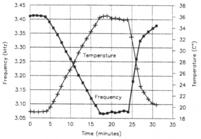
Fig 5 - One temperature-drift run made with the oscillator of Fig 4. The circuit was not enclosed in a shield box.
Fig 6 shows the results of a first attempt at temperature compensation. I replaced a 270-pF NP0 capacitor with a 100-pF NP0 capacitor paralleled by a 150-pF polystyrene capacitor. This resulted in a drift of 1.3 kHz for the same temperature swing that initially produced 3.5 kHz.
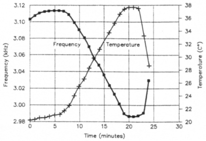
Fig 6 - Thermal drift characteristic of the Fig 4 oscillator with some of its NP0 tuned-circuit capacitance replaced by polystyrene-film units. The polystyrenes' negative temperature coefficient offsets drift in the oscillator inductor. (In this case, the result was modest overcompensation; see text.) As in the Fig 5 test, the oscillator was not enclosed in a shield box.
These measurements suggest a simplified way of using the oven: Rather than recording data at one-minute intervals, record the initial frequency and temperature in your notebook. Then apply heat to the oven for a long enough time to produce a temperature rise of 10 to 15 °C. Record the final conditions. This is enough information to calculate a temperature coefficient of frequency (TCF) for the circuit. I used this abbreviated procedure for almost all of the measurements reported in this article.
Calculations in temperature compensation
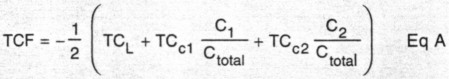
If a tuned circuit consists of an inductor with a temperature coefficient of TCL that is paralleled by two capacitors, C1 and C2, with temperature coefficients TCc1 and TCc2, respectively, the temperature coefficient of frequency is then TCF, where
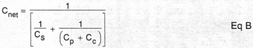
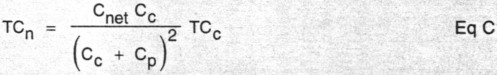
If a compensating capacitor, Cc, is paralleled with a capacitor Cp and the combination is placed in series with a capacitor Cs, the combination has a net capaci tance C with a net temperature coefficient TCn, where
Temperature compensation by numbers
Frequency drift with temperature is usually specified in terms of a fractional change per degree of temperature change. The run in Fig 6 produced a change of about 80 Hz for each degree-Celsius of temperature swing with the oscillator operating at 7 MHz. This corresponds to a change of 0.0011 percent per degree. A more convenient specification replaces percentages with parts per million (ppm). The TCF for the VFO of Fig 6 is -11.4 ppm/°C. The negative sign indicates that frequency decreases with increasing temperature.
Components are specified in a similar way. The temperature coefficient of inductance (TCL) for a coil wound on a carbonyl SF toroid (Micrometals -6 designator) is +35 ppm/°C. That is. the inductance will increase by 35 millionths of the total inductance for each degree-Celsius increase in temperature. Note, however, that this value predominantly describes how the core permeability changes. The inductor TC is often higher, usually because its wire is not wound tightly against the core. (Heavier wire results in higher Qs but is harder to wind tightly than thinner wire; a more stable coil may therefore result from the use of smaller wire than might be optimum for Q.)
The TCF is related to the coefficients of the individual components by the equation given in the sidebar, "Calculations in Temperature Compensation." There is a factor of one half in the sidebar's Eq A; The TCF is half of the temperature coefficient of the components. The sidebar example analyzes a parallel tuned circuit with one inductor and two capacitors with combined value of Ctotal. The overall temperature-compensating effect of a capacitor diminishes by the ratio of its value to the circuit's total capacitance.
Capacitor manufacturers specify their parts' thermal characteristics, but this data may be omitted in distributors' catalogs to save space. The most stable capacitors have a temperature coefficient of NP0. NP0 is a shorthand designation for negative-positivezero. This characteristic depends mainly on the material from which the capacitor is made. Because manufacturing processes operate within tolerances that allow some degree of error and variation, temperature coefficients are sometimes specified in greater detail. These specifications include terms like C0G, C0H and C0J, all of which are variations on the NP0 specification. A C0G capacitor has a TC of 0 ppm/°C with an uncertainty of ±30 ppm/°C.
Temperature compensation involves counteracting an oscillator's inherent thermal instability by adding instability equal in value but opposite in sign. Drift attributable to an oscillator's tuned-circuit inductor usually plays the largest role in thermal instability, although this may not be true if some especially "bad" or poorly specified capacitors are present. Inductor TC is usually positive and can be compensated by a capacitor with a negative TC. A common temperature-compensating capacitor type (a ceramic "mix") has a TC of -750 ppm/°C; this is designated as a N750 part. The compensating capacitor's coefficient is usually much larger than that of the inductor to be compensated because the compensating component replaces only a tiny fraction of the total resonator capacitance.
As an example, consider the oscillator evaluated in Figs 4 and 5. Based on data recorded at 5 and 17 minutes, the oscillator TCF (as determined using the sidebar's Eq A) was -28.0 ppm/°C. The circuit used all NPO capacitors. Assuming that these parts are drift-free, the inductor has a temperature coefficient of +56 ppm/°C.
The modified oscillator that produced the data of Fig 6 used parallel capacitors, 440 pF of NPO plus 150 pF of polystyrene (TC,-150 ppm/°C). According to the sidebar's Eq A, the approximately compensated oscillator should have a TCF of -9 ppm/°C. The measurements on which Fig 6 is based reflect a TCF of-11.5 ppm/°C. Compensation would be exact with 220 pF of N150 and 370 pF of NP0 capacitance.
Observations on the method and its limits
The methods presented are incomplete because the test chamber is capable only of positive temperature excursions. Extending the process to cooler extremes should not be difficult. For example, a small thermal chamber could be put inside a household freezer. After a suitable cooling period, the heat source could be turned on to bring the oscillator under test up to room temperature.(3)
The compensation process should not be asked to deliver miracles. The folly of such an effort is evident from the sidebar's Eq A, which shows how two or three thermal effects are balanced against each other. As one component becomes less stable, the others must be made similarly unstable, but in the opposite direction, such that the overall result is zero net drift.
As a better design procedure, use the most stable inductor available. Resonate it with the most stable capacitors available to you. Then use compensation only to make this good design even better. This approach illustrates a concept that finds its way through much of science: Two large effects are not expected to balance each other unless there is good physical justification for the balance. This idea, applied to VFO design, was emphasized by Roy Lewallen, W7EL, in his earlier work.
Ham junk boxes typically do not contain capacitors with negative temperature coefficients. One major exception to this is corn-mon: polystyrene film capacitors. Most of the polystyrene capacitors I've used have come from Mouser Electronics. They were specified to have a temperature coefficient of -150 ppm/°C. Such relatively stable, low-TC performance should be used in preference to smaller-valued, but higher-coefficient N750 parts.
Examining compensation more closely further complicates the process. Especially at higher frequencies, the parasitic reactances of a circuit's active devices become significant. The analysis presented in this article assumes that drift is linear with temperature. Linearity implies that a component temperature coefficient is constant, but this only approximates reality. Compensating an oscillator over a wide temperature range can be a very difficult chore.
Conclusions and quasi-lore
I found this project very enlightening, and it suggests the following conclusions and observations. Some of these are rather specific, often pertaining to technical lore long believed by amateur constructors, while others are more general.
The first, and certainly the strongest, conclusion that emerges is that temperature compensation is neither difficult nor expensive. The equipment needed is usually available in an experimenter's collection of goodies. While lore provides a starting point for design, it is no substitute for measurement.
I'll now present as lore some of the generalities that have come from the experiments, with the thought that they can and will be confirmed through additional reader measurements:
- Excellent components are available to radio amateurs of today. This allows good compensation results to be realized with single-point methods. That is, we can do one TC measurement between two relatively close temperatures and be assured that the results will apply over a wider range.
- There is no fundamental thermal stability difference between a Hartley or a Colpitts oscillator, or any other topology that I have tried. It's important that the oscillator operate with current limiting.(4) Voltage limiting can severely degrade resonator Q, leading to compromised stability.
- Micrometals -6 toroid material, when used with high-quality NPO capacitors, form the most stable starting configuration I have found. The run of Fig 5 is typical (TCF = -28 ppm/°C). After compensation, several oscillators have yielded TCFs between 1 and 2 ppm/°C. I have not yet investigated the newer -7 material that some builders have found useful.
- Warm-up drift is interesting as a measure of self-heating. However, it is a poor indicator of stability when compared with a temperature run in a simple thermal chamber.
- A search for readily available, inexpensive NP0 capacitors that perform as advertised produced two viable sources. One part tested was a 470-pF monolithic ceramic (Mouser Electronics 21RD647). The other part tested was a 220-pF ceramic (Digi-Key P4460, manufactured by Panasonic). Other parts from the same catalog groups are probably as stable. This experience is much more encouraging than a similar experiment done a few years ago.
- A tuning diode I examined (a Motorola MV209) exhibited, as expected, a high TC (+442 ppm/°C). Work continues on active compensation circuits, however. Voltage-regulator circuitry used with tuning diodes must be designed with care because Zenerdiode temperature drift can confuse compensation results.
- Some builders (amateur and otherwise) have been building oscillators from available, but apparently mismatched components. Experiments confirmed the variable performance of these methods. One oscillator, built using a -6 toroid and polystyrene capacitors alone (no NP0 units), was overcompensated (TCF = +24 ppm/°C - better than expected, but not recommended). Another test oscillator, built with a -2 ("carbonyl E") core, exhibited a TCF of -63 ppm/°C when tuned with NP0 capacitors. Replacing the NP0 capacitors with polystyrenes yielded a TCF of +8.2 ppm/°C. This topology is also not recommended, because its temperature depends on two relatively large coefficients working against each other. As mentioned earlier, better designs aim for the best stability with each and every component.
- Coils should be conditioned for best sta bility. Bending and stretching the coil wire during winding creates mechanical stresses in the windings. Heating the coil, and then allowing it to cool to ambient, relieves those stresses. I readily observed this effect with the temperature chamber: A new coil, just wound and subjected to a thermal cycle, starts at a frequency that is different than the final one. Subsequent cycles, however, show repeatable, reversible behavior. Temperature-chamber tests confirmed a method of annealing an inductor in boiling water as suggested by W7EL.(5)
- This article considers only toroidal inductors. They are presently available, offer higher Q for a given volume than other forms, and are well-characterized. Some workers continue to advocate slug-tuned or air-core coils, but have not offered specifications or measurements.
Science can help you build better oscillators if you give it a chance. You can have "rock stable" oscillators if you're willing to build and apply some simple measurement gear.
Acknowledgments
I'd like to extend my thanks to numerous ham colleagues who have shown an interest in this project, especially W7EL; Terry White, KL7IAK; and K8BHZ. Thanks also to Steve Bingham, who contributed an LM3911 from his junk box.
Notes
- R. Lewallen, "An Optimized QRP Transceiver," QST, Aug 1980, pp 14-19; also see Feedback, QST, Nov 1980, p 53. The Optimized QRP Transceiver article also appears in re-edited form in the 1992-1994 ARRL Handbooks.
- R. Hayward and W. Hayward, "The 'Ugly Weekender,'" QST, Aug 1981, pp 18-21. (The Ugly Weekender also appears in re-edited form in the 1992-1994 ARRL Handbooks.) Also see oscillator comments in W. Hayward and D. DeMaw, Solid-State Design for the Radio Amateur (Newington: ARRL, 1977 and 1986).
- Brian Mattson, K8BHZ, has suggested using the Peltier-effect coolers that are now available as 12-volt-powered mini-refrigerators. Relatively inexpensive and available in a size intended to cool six-pack-sized objects, they might be an ideal basis for a small environmental chamber.
- W. Hayward, Introduction to Radio Frequency Design (Englewood Cliffs, NJ: Prentice-Hall, 1982), Ch 7.
- See Note 1.
W7ZOI, Wes Hayward.