The nearly perfect amplifier
Have you ever bought a car and thought that everything about it was perfect? Or do you always wish it had a few other nifty or safety features? It's the same with ham power amplifiers. Here are some modifications that will add some nifty and safety features - to the amplifiers, not the cars.
After the article "Circuit Improvements for the Heath SB-220 Amplifier" was published in the November and December 1990 issues of QST, I began to receive letters and phone calls from Amateur Radio operators who were contemplating buying an HF amplifier. They wanted to buy an amplifier that needs no circuit improvements - that is, a perfect amplifier. What follows is a discussion of some design features that - in my opinion - would be present in a perfect, or a nearly perfect, amplifier.Cathode considerations
In a directly heated cathode, a ditungsten carbide layer on the hot tungsten (alloyed with about 1.5% thorium) filament wire emits electrons. In an indirectly heated cathode, the filament (the heater) heats a nickel cylinder that is coated with strontium oxide and barium oxide. This coating is relatively frangible, but highly emissive.
Ditungsten carbide is commonly made by heating tungsten in an atmosphere of acetylene (C2H2) gas. Carbon atoms in the gas break their bonds with hydrogen atoms and bond with tungsten atoms to form ditungsten carbide on the surface of the filament wire. Since it is atomically linked to the underlying wire, the ditungsten carbide layer is very durable. During use, the process reverses. Ditungsten carbide gradually loses carbon and changes back to tungsten. Extra heat exponentially accelerates this process. The cathode is worn out when the carbon is mostly used up.
After their cathodes are worn out, large external-anode amplifier tubes are commonly "recarburized" with acetylene, vacuum pumped, and resealed. This restores full emission. Although it is possible to recarburize a 3-500Z, doing so is not economically feasible.
Each type of cathode has advantages and disadvantages. A nickel cylinder has much-less inductance than a tungsten wire. Directly heated cathodes are relatively poor performers above the low VHF range, whereas some indirectly heated cathodes can perform satisfactorily at 2500 MHz. A directly heated cathode typically warms up in less than one second, while few indirectly heated cathodes can warm up safely in one minute (three to five minutes is not uncommon). However, the major disadvantage of indirectly heated cathode amplifier tubes is cost. In terms of dollars per watt, they are much more costly than 3-500Zs.
Cathodes deserve respect. Filament voltage and filament inrush current are areas of special concern.
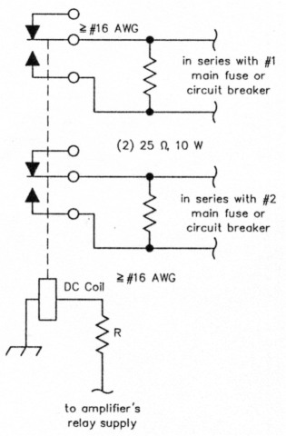
Fig 1 - Step-start circuit for amplifiers that are designed for dual-voltage operation (120/240 V). In effect, the timing capacitor for the circuit is the high-voltage filter capacitor. The relay's coil voltage is approximately the same as the dc output voltage of the amplifier's relay supply. A contact rating of 10 A is adequate for 1500-W amplifiers Adjust R for relay pull-in when the high voltage reaches about 65% of normal after turn-on. Typical pull-in time is 1 ± 0.5 second. R will be roughly half of the relay's dc coil resistance.
Filament voltage
For optimum life from a directly heated cathode, the filament voltage should be just above the voltage where PEP output begins to decrease. As the cathode ages, filament voltage needs to be increased gradually to restore full output. Using this technique, commercial broadcasters typically achieve an operating life of 22,000 hours from amplifier tubes with directly heated cathodes.
According to Eimac's Care and Feeding of Power Grid Tubes, every 3% rise in directly heated cathode filament voltage results in a 50% decrease in life due to carbon loss. Yes, each additional 3% rise in filament voltage decreases the life by half. Expressed mathematically, cathode life is proportional to (E1/E2)23.4, where E, is the lowest filament voltage at which normal PEP output is realized and E2 is the increased filament voltage.
It's easy to make the filament voltage adjustable when the filament is powered by its own transformer. All that's needed is a small rheostat in series with the primary. For dual-voltage, dual-primary transformers, a dual, ganged rheostat is required. When the filament is powered by a winding on the high voltage transformer, making the filament voltage adjustable is more difficult since the rheostats must be connected to the low voltage secondary winding - and dual, ganged 0.01 Ω, 30-A rheostats are not to be found in your local Radio Shack.
An indirectly heated cathode can be permanently damaged by being operated below its rated minimum filament voltage. When operated above its maximum filament voltage rating, an indirectly heated cathode quickly boils off emissive material. Errant emissive material is bad news when it lands on the grid. For maximum cathode life in HF service, an indirectly heated cathode should be operated at the rated minimum filament voltage. This can be accomplished best with a regulated dc supply. Set it once and forget about fluctuations in the electric mains voltage.
Filament inrush current
Directly heated cathode filaments are commonly two vertical meshing helices (coils) of tungsten wire that are suspended by their ends (see September 1990 QST, page 15). The conductance of tungsten at room temperature is about 8.33 times the conductance at its normal operating temperature. Thus, the start-up current for a 15-ampere filament can be 125 amperes.
In a high-amplification tube such as the 3-500Z, the filament helices clear the grid cage by a distance of only a few thousandths of an inch. If the position of the filament changes, a grid-to-filament short may result. Therefore, it is prudent to limit filament inrush current in order to minimize thermal and magnetic stresses. For many of its smaller directly heated cathode amplifier tubes - such as the 3-400Z and 3-500Z Eimac recommends that filament inrush current be limited to no more than double the normal current.
Since the grid-to-cathode clearance in an indirectly heated cathode is not affected by movement of the heater inside the rigid nickel cylinder, indirectly heated cathodes are not affected by inrush current.
Measurements
I tested the filament inrush current in a popular factory-built MF/HF amplifier with a pair of 3-500Zs. Since each tube's operat-, ing filament current is 14.7 A, the inrush current should not exceed 29.4 A, but I measured 34 A of inrush current per filament. Eimac rates the filament voltage at 4.75 V minimum to 5.25 V maximum but the filament voltage measured 5.31 V. With 4.8 V instead of 5.31 V, the useful life of the 3-500Zs would be about ten times longer. I measured the filament voltage in a factory-built single 3-500Z amplifier. The filament voltage was over 5.7 V. At this voltage, the cathode would probably be worn out in 400 hours of operation - and this one was.
The 8877 has a filament voltage rating of 4.75 V minimum to 5.25 V maximum; for HF communications service, the optimum filament voltage is 4.75 V. One popular commercial amplifier operates its 8877 filament at about 5.95 V when the amplifier is operated at the US-standard 120/240 V. Operating an 8877 at a filament voltage of 5.95 V is recommended for those people who have more money than brains.
A simple ac voltmeter
For measuring ac filament voltage, linearity at the low end of the meter scale is not important. With this in mind, designing an ac voltmeter using a dc meter movement is much easier than would otherwise be the case. All that's needed is a half-wave rectifier using a Schottky diode, a capacitor and a few resistors. The meter can be the amplifier's multimeter. All that the operator needs is two marks on the meter scale - one for minimum voltage and the other for maximum voltage.
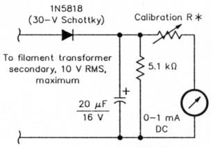
Fig 2 - How to measure the ac filament voltage with a dc meter. Calibrate R with a standard voltmeter connected to the filament pins on the tube socket, so as to compensate for the voltage drop in the filament choke.
Grid protection
I have performed autopsies on too many kaput amplifier tubes that died in HF amplifiers. Some of these tubes had damaged grids - but the damage was the unique type that is caused by VHF or UHF current. I have never found a grid that was damaged by excessive HF grid current. Perhaps this isn't so strange. I'm sure it's possible to roast a grid; tuning up key-down for a couple of minutes on 10 meters with the load capacitor set for 40 meters comes to mind. This would result in high grid current and almost no RF output. However, since most people - myself included - tune a grounded-grid amplifier for maximum RF - and maximum RF virtually coincides with normal grid current - very few people are likely to overheat a grid. Thus, complex electronic grid-protection circuits are unnecessary. A major disadvantage of electronic grid-protection circuits is they are not effective against the major source of grid damage - sudden, large bursts of VHF or UHF grid current. A more foolproof method of protecting the grid is a fuse or fuse resistor. Carbon-film resistors make good grid fuses.
Glitch protection
During a major glitch, the anode (plate) current meter is subjected to a current surge as the HV filter capacitors discharge. Such a current is typically several hundred peak amperes - not exactly courteous treatment for a 1-A meter. However, the peak current will be much higher if a resistor is not used to limit the short circuit current that can be delivered by the HV filter capacitors. The current-limiting resistor is placed in series with the positive output of the filter capacitors. A 10 Ω, 10-W wire-wound resistor is adequate for up to 3 kV and 1 A. Since the current-limiting resistor will be dissipating many kilowatts during a major glitch, it should be a rugged glass-coated (ie, vitreous) type. If a glass-coated resistor opens during a major glitch, it won't be throwing large chunks of shrapnel around - like a rectangular ceramic-cased resistor often does.
If the positive high voltage briefly arcs to chassis ground - because of lint, a tiny insect, an intermittent VHF parasitic, or an errant hair - the negative high-voltage circuit will try to spike to several kilovolts negative. In the real world, this type of glitch is not an uncommon occurrence. Anything that gets in the way of the negative spike may be damaged. Since the grid-current meter is normally connected between chassis ground and the negative high-voltage circuit, the meter can be exposed to kilovolts at hundreds of amperes. I heard about one grid current meter in a homebrew amplifier that exploded during a glitch. The glass from the meter landed on the floor.
The easiest way to protect a current meter is to connect a silicon rectifier diode across it or across its shunt resistor. Usually, only one diode (connected with its cathode band to the meter's negative terminal) is needed in parallel with a meter.
It may take more than one diode to protect a meter shunt resistor. A silicon diode begins to conduct at a forward voltage of about 0.5 V. To avoid affecting meter accuracy, the operating voltage per protection diode should not exceed 0.5 V. For example, a 1-Ω shunt, for a reading of 1 A full-scale, has 1 V across it. Thus, two protection diodes would be needed to preserve meter accuracy. If the shunt resistor for a 1-A full-scale meter is 1.5 Ω, three diodes are needed.
Protection diodes should not be petite. Big, ugly diodes with a peak current rating of 200 A or more are best. I have seen smaller diodes - and the meter they were supposed to be protecting - literally blown away by a glitch. After some bitter experiences with lesser diodes, I began using the 1N5401. In small quantities, the 1N5401 costs about 20 cents each. It is rated at 200 A for 8.3 ms, 3 A rms, and 100 PIV. Other diodes from the 1N5400 family will work as well. During an extremely high current surge, a glitch-protection diode may short out - and, by so doing, still protect the precious parts. Replacing a shorted protection diode instead of a blown meter is almost fun.
A brief high-voltage flashover can damage an indirectly heated cathode tube. Here's how: In many amplifiers, one side of the filament/heater is grounded. The cathode is connected to the negative HV circuit. If the negative HV spikes to several kilovolts, the cathode will arc to the grounded filament. At a minimum, this breaks down the insulation between the heater and the cathode. Sometimes the heater wire burns out - and sometimes the cathode arcs to the grounded grid. Either way, the tube is kaput. There have been many 8877s and other indirectly heated cathode amplifier tubes that died this way - all for lack of 60 cents worth of glitch-protection diodes.
So why don't manufacturers of such amplifiers protect the negative HV circuit from spikes? The answer is an electronic Catch-22. Even though it's likely that no amplifier manufacturer has ever seen a grid that was damaged by HF grid current, they seem to feel that electronic over-current protection for the grid is important. However, electronic over-current "protection" circuits for grids are not compatible with things that limit the voltage from the negative HV circuit to chassis ground. Thus, in an attempt to protect the amplifier tube from one perceived problem, designers leave the tube vulnerable to assassination from common occurrences.
To prevent the negative HV circuit from spiking to several kilovolts, connect a string of 200-A (or greater) glitch-protection diodes from the negative terminal on the high-voltage filter capacitor to chassis. Each diode will limit the voltage across itself to about 1.5 V. Typically, three diodes are needed - thus limiting the spike to about 4.5 V. The diode polarity is with the cathode band toward the negative high voltage. With one simple wiring change, the same string of diodes can also protect the grid-current meter and the anode-current meter.
Power Supplies
Transformers
Virtually all transformers use paper to separate and insulate each layer of windings, and paper is hygroscopic - it absorbs water vapor from the air. The presence of water reduces the insulating ability of the paper. In time, insulation breakdown is likely. The solution is to pot the windings; plastic resins are best for potting, and petroleum tar is next best. Since potting fills up the air spaces in the windings - and air is a poor heat conductor - potting improves heat transfer, thereby reducing internal temperature and decreasing the likelihood of failure. Potting adds very little to the initial cost of a transformer and subtracts substantially from the long-term cost by increasing the transformer's lifetime.
Filters
Capacitor-filtered power supplies are the norm in Amateur Radio amplifiers, because of their light weight, relative ease of obtaining high dc potentials, good transient-current voltage regulation (a must for SSB), and cost. Since choke and swinging-choke filters can not handle transient current loads, the only alternative for SSB use is a resonant-choke filter, which has advantages and trade-offs. A resonant-choke filter is tricky to tune, heavy, and expensive, and it requires a much-higher bleeder current than a capacitor filter requires. However, a resonant-choke filter demands only about one-sixth as much peak power from the electric mains as a capacitor filter demands. This means that for 120-V operation, where power is much more limited than with 240-V operation, a resonant-choke filter is clearly the better choice.
Rectifiers
The most frequent failure mode for high- voltage power-supply rectifiers is too much reverse current. This problem can be virtually eliminated in full-wave rectifier circuits by making sure that the total peak inverse voltage in each string of diodes exceeds the peak secondary voltage of the high-voltage transformer by a comfortable margin; 50% sounds comfortable to me.
Modern solid-state rectifiers are made differently than they were 30 years ago. In those ancient days, rectifiers did not have uniform capacitance. In an attempt to help equalize the peak reverse currents in series-connected rectifiers, a parallel resistor and capacitor was connected to each rectifier. It was felt that swamping 50 to 100 pF with 10,000 pF (0.01 µF) would help. In practice, it didn't work too well since the tolerance of the capacitors used was typically -20% to +80%. Another problem is that the resistors that were typically used (470 kΩ, 0.5 W) were rated at 250 V absolute maximum. It is hardly safe to use one of these resistors with a 1000-PIV rectifier. As a result, "equalizing" did more unequalizing than anything else. Even after rectifier technologyimproved, people hung on to the old habit of using parallel resistors and capacitors.
There is a flaw in the logic behind using rectifier equalization. In any series circuit, the currents in all of the elements are exactly equal. Thus, when rectifiers are in series, the reverse-current burden is exactly the same for each rectifier. How is it that something that is already exactly equal needs to be equalized? It should go without saying that series-connected rectifiers should always be of the same type. Mixing rectifiers with different junction capacitances can oause a problem.
There is one instance where equalizing resistors and capacitors are a good idea. Voltage spikes come in two flavors - positive and negative. In a full-wave capacitor-filter rectifier circuit, the energy from positive and negative voltage spikes is simply rectified and harmlessly stored in the filter capacitor. However, in a half-wave rectifier circuit only one polarity is rectified. A voltage spike of the other polarity cannot be absorbed by the filter capacitor. Instead, the potentially destructive spike appears across the rectifiers. Placing a capacitor across each rectifier helps to limit reverse spikes. A better solution is to connect a metal-oxide varistor across each half-wave rectifier - or to use a full-wave rectifier circuit.
Electrolytic capacitor equalizing resistors
A resistor's voltage rating takes precedence over its power rating. One-watt carbon-composition resistors have a maximum voltage rating of 350 V. For example, it takes 469 V to dissipate 1 W in a 220-kΩ resistor (E=[PR]0.5). In the past, some amplifier engineers decided that 220-kΩ, 1-W carbon-composition resistors would make good (and cheap) voltage-equalizing resistors for 450-V electrolytic capacitors - considerable overvoltage for 1-W parts! When a carbon-composition resistor is operated above its maximum voltage rating it changes resistance - exactly what you don't want in a voltage divider. Capacitor failure is likely in a string of equal-value electrolytic capacitors connected in series when the voltages across the capacitors is not the same. Even when they are operated within their voltage rating, carbon-composition resistors change resistance with age. Thus, 2-W carbon-composition resistors, which are rated at 500 V, are not the answer. Metal-oxide-film (MOF) resistors are far superior to carbon-composition resistors. A 3-W 100-kΩ MOF resistor makes an excellent equalizer resistor for 450-V capacitors. Lower values of resistance create extra heat - something that electrolytic capacitors do not tolerate well.
Biasing
The operating bias in most amplifiers is not adjustable; a single Zener diode is typically used. The resulting zero-signal anode current (the idling current) is seldom optimum. Adjustable bias would be nice. The solution: obtain the operating bias from a series string of forward-biased rectifier diodes. By switching the number of diodes in and out with a rotary switch, the bias can be changed in approximately 0.7-V increments.
Another area that could be improved on is the method of bias switching between receive and transmit. In this modern age there is no reason to use a pokey, noisy mechanical relay to switch bias. An optoisolator coupled to a transistor switch can do this job better and cheaper. An electronic bias switch is more than fast enough to keep up with modern high-speed RF relays.
Electronic bias switches that are RF actuated create two problems. The amplifier tube switches between linear bias and nonlinear bias during softly spoken syllables of speech, causing choppy-sounding audio and splatter. These two problems are eliminated when the electronic bias switch is controlled by the current that passes through the RF-relay's coils.
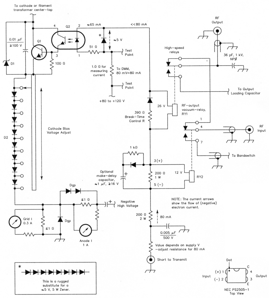
Fig 3 - Adjustable electronic cathode bias switch for cathode currents up to 3 A.
| D1 | 30- to 51-V transient voltage suppressor (Digi-Key part 1.5KE51CA-ND or similar. |
| D2 | For collector currents between 1 and 3 A, use 1N5401 diodes. The number of diodes making up D2 may have to be increased in some amplifiers. |
| Dgp | Glitch-protection diode (1N5401 or similar, 200-A peak or greater). |
| Q1 | NPN, 80 to 100 V, 10 A (TIP 33B, TIP 33C, etc). (The collector-to-emitter voltage drop across Q1 is about 1.4 V on transmit. On receive, the drop depends on the supply voltage to the tubes and also on the particular tubes used; typically the drop on receive is 24 to 30 V. Q1 needs only a minimum heat sink.) |
| Q2 | NEC PS2505-1 optoisolator, input-protected, 80-mA maximum input, Vce=80 V, gain of 300% or greater. |
| RY1 | Kilovac HC-1 or Jennings RJ-1A (7 A maximum at 32 MHz). |
| RY2 | Matsushita NR-HD-12V reed relay (Trio-Kenwood part number S51-1429-05). |
The unspecified diodes are 1-A or greater, 200 V PIV (1N4003, 1N5401, etc). The unspecified resistors are 1/4-W.
High-Speed Relays
The switching time of a conventional relay is 15 to 25 ms - switching in a somewhat stentorian manner. Such relays have traditionally been used for RF and bias switching in HF amplifiers. This was acceptable when transceivers also used conventional relays. Currently manufactured transceivers are designed for AMTOR, QSK CW, and reasonably quiet SSB-VOX operation. Such transceivers switch quickly and quietly. Japanese transceivers often use a Matsushita (Panasonic) NR-HD-12V reed relay to switch the RF output. Provided that the SWR isn't ridiculous, this relay can dependably switch 150 W of RF. It works well in an HF amplifier when it is used to switch the input RF signal. This relay is available in the US as a spare part for Kenwood and Yaesu radios.
Although Matsushita refuses to sell its NR-HD-12V relay to US Amateur Radio equipment manufacturers, a US reed relay manufacturer could probably come up with a similar relay, if there were enough demand. Jennings and Kilovac manufacture high-speed relays that will switch kilowatts of RF. The Jennings relay is the RJ-1A; Kilovac's is the HC-1. I have been using these two relays for many years to switch the output in my amplifiers. When mounted with silicone rubber, they are fairly quiet. When used with a speed-up circuit, either relay can switch in under 2 ms. I use a speedup/sequencing circuit that prevents them from being hot-switched, and have not had a relay fail in this circuit.
It makes little sense to be currently building - or buying - an amplifier that switches in 25 ms. If such an amplifier is used with a modern radio, it would be technically more correct to say "hot-switches in 25 ms."
VHF stability
On page 72, the 1926 edition of the ARRL's The Radio Amateur's Handbook told us how to build an improved VHF parasitic suppressor - one that provides better VHF stability than ordinary parasitic suppressors. The logic was elementary. A suppressor is supposed to dampen a circuit. Since low Q is synonymous with high dampening, build a suppressor with low Q. Instead of using a conductor with a high Q at VHF - such as copper or silver - use a conductor with low Q at VHF - resistance wire. The 1926 Handbook said, "The combination of both resistance and inductance is very effective in limiting parasitic oscillations to a negligible value of current."
After 1929, someone forgot to include this information in the Handbook. In those days, the oversight probably didn't matter very much. Electron tubes generally had poor amplification at VHF, so VHF instability was not much of an issue. During the ensuing decades, Amateur Radio operators and amplifier manufacturers got into the habit of using parasitic suppressors made from copper - or, even worse - silverplated copper. This was an easy habit to get into; copper and silver can be soldered easily and cheaply. Meanwhile, the VHF amplification of electron tubes kept improving. Modern tubes need 1926-vintage parasitic suppressors with a low Q at VHF!
VHF parasitic oscillation can cause bandswitch arcing, tuning-capacitor arcing, and a large pulse of grid 'current. The pulse of grid current is so large that a powerful magnetic force is exerted between the grid and filament. In a 3-500Z, this force is capable of bending the hot tungsten filament helices and causing a filament-to-grid short. Of course, there is a trade-off to using suppressors with a low Q at VHF. On the 10-meter band, they reduce amplifier output by roughly 0.08 dB. This should come as no surprise: anything that dampens VHF resonance is bound to have some effect at 29 MHz. A VHF suppressor that does not get hot on 10 meters isn't doing its job.
Even though much has been published about VHF parasitic oscillation, amplifiers are still being built without the benefit of suppressors with a low Q at VHF. Some amplifier manufacturers presently take a dim view of using such suppressors. Even if you have signs of parasitics, such as intermittent bandswitch arcing, they will void the warranty if you remove their suppressors with a high Q at VHF and install replacements with a low Q at VHF.
Step-start
Large power supplies need something to soften the shock of start-up. A 10-A DPST (normally open) or a 10-A DPDT relay and two 25-e, 10-W resistors are just about all that's needed to add a good step-start circuit to the average 1500-W amplifier. The step-start circuit belongs in series with the main fuses or circuit breakers. This way the filaments will also enjoy the benefit of a gentle start-up.
Is more gain always better?
Today, the more or less standard in transceiver output is 100 W. There are amplifier tubes that can easily be ruined by 100 W of drive. A good example is the 3CX800A7. Using 100 W of drive will eventually strip flakes off the cathode. The flakes can become lodged between the cathode and the grid cage - creating a short. Even a pair of 3CX800A7s is clearly overdriven by 100 W. Doing so probably won't flake the cathodes, but it can cause rotten splatter. The fix is simple: connect a 40 Ω resistor in series with each 3CX800A7 cathode. These (cathode RF negative feedback) resistors reduce gain. As a result, the amplifier won't be driven above its absolute maximum ratings - and into nonlinearityby a 100-W transceiver.
Cathode RF negative feedback resistors are better than having a matched pair of 3CX800A7s - the cathode currents automatically equalize themselves. And unlike all ALC circuits, cathode feedback resistors work instantaneously - eliminating ALC's generic flaw - leading-edge splatter on SSB. (Amplifier-to-transceiver ALC only works properly on modes with a constant signal level, such as RTTY and FM.) When a single 3-500Z is driven by 100 W, it also splatters. Although the rated drive is around 55 W, manufacturers of amplifiers with a single 3-500Z give the green light to driving their amplifiers to an anode current of up to 550 mA - a feat that requires using about 100 W of drive. On SSB, this produces distortion and splatter. Eimac rates the anode current at 400 mA absolute maximum. It takes a 25-S2 cathode feedback resistor to make a 3-500Z happy with 100 W of drive. The resistor goes in series with the cathode coupling capacitor.
It would be nice if amplifiers were designed to be compatible with 100 W of drive.
Adjustable tuned inputs
Modern MF/HF transceivers with a solid-state output stage use an untuned push-pull RF output stage. In order to meet FCC requirements on spurious emissions, passband LC filters are used. Such filters introduce inductive and capacitive reactance at various frequencies within their passbands. In other words, the output impedance of a modern transceiver is seldom 50 ± j0 Ω. This is of no consequence unless you happen to be driving a tuned input in a grounded-grid amplifier. In this case. the filter reactance interacts with the reactance of the input capacitor in the pi-network tuned input. The length of the coax between the filter and the tuned input affects the way the reactances interact. As a result, the input SWR can suffer. If the SWR is too high. the transceiver will automatically cut back on power.
For example, to obtain Eimac's recommended Q of 2, approximately 200 pF of input capacitance is needed for a tuned input on the 10-meter band. In actual practice, however, a 50-pF input capacitor may produce the best SWR with a particular model transceiver and a particular length of coax. A different model transceiver or a different length of coax may require a different-value input capacitor.
It would be nice if an amplifier's input capacitors on the tuned inputs could be readily adjusted.
Summary
Here is a list of the various features discussed in this article and the approximate cost of including them in an amplifier design.
- Adjustable filament voltage and a simple filament voltmeter using the existing multimeter, $10 to $20.
- Step-start relay circuit, $7.
- Adjustable electronic bias switch, $2.
- High-speed RF relays, $90.
- Parasitic suppressors with a low Q at VHF, $1.
- Separate high-voltage and filament transformers - preferably potted; metal-oxide film equalization resistors for electrolytic capacitors; no so-called equalizers on high-voltage rectifiers, $60.
- Make the amplifier compatible with 100 W of drive, $1.
- Glitch-protection diodes for the meter circuits and the negative high-voltage circuit, 30 cents.
- A 1042, 10-W glass-coated resistor in series with the positive lead of the high-voltage power supply, 76 cents.
- Adjustable input capacitors on the tuned inputs. $6.
Obviously there are other important elements to consider in amplifier design. The elements discussed above are ones that are frequently overlooked.
AG6K, Richard Measures.