A receivingantenna that rejects local noise
Simplicity and performance combine to give birth to a compact antenna you'll want to have!
Noise can make a ham's life miserable on any amateur band. As we approach the minimum of the sunspot cycle, many hams are discovering that noise can be particularly frustrating on the low bands. In summer, static crashes caused by thunderstorm lightning can totally mask weak signals on the 160, 80, and 40 meter bands. During other seasons, power-line noise, noise from household appliances, and incidental radiation from home electronic products often limits reception.
A recent QST article by Floyd Koontz, WA2WVL,(1) describes a small receiving antenna for the low bands that provides a cardioid directional pattern. This pattern can reduce noise and QRM from the rear. As I marveled at the elegance and simplicity of Floyd's design, I realized that the antenna did have one shortcoming: Because it is vertically polarized, the antenna responds strongly to local noise propagated by ground waves. I wondered whether it was possible to devise a receiving antenna to better reject local noise.
The Ground Wave
Most hams who operate HF are familiar with the sky wave (or space wave) that's responsible for long-distance ionospheric propagation. See Figure 1A. The space wave has two components: The direct wave propagates along a straight line from the transmit antenna toward the ionosphere. The ground-reflected wave bounces off the earth's surface and heads in the same direction.
The space wave also exists for local propagation, as shown in Figure 1B. The direct wave travels in a straight line between the transmit and receive antennas, while the ground-reflected wave takes a midpoint bounce. But when the antennas are close to ground, the direct and reflected waves nearly cancel, leaving a very small residual space wave. When the antennas are right at the earth's surface, the waves cancel completely. So what makes local communication possible? Answer: A third wave, called the surface wave, that exists for antennas close to ground. This wave diminishes in intensity as you increase antenna height. The surface wave exists only near the surface of the earth. The combination of the direct wave, the ground-reflected wave, and the surface wave is called the ground wave.(2)
Surface-wave intensity varies with frequency and ground conductivity. It's stronger at low frequencies and for highly conductive ground. But the most important property of the surface wave is its polarization sensitivity. The surface wave is much weaker for horizontal fields. For example, on 80 meters the broadside ground-wave response of a short piece of wire is about 34 dB lower when oriented horizontally. The difference is about 42 dB at 160 meters.(3)
The surface wave makes local AM radio broadcasting possible. Because of the poor propagation of horizontally polarized ground-wave signals, AM broadcasters universally use vertical polarization. The same phenomenon causes vertical antennas to pick up much more local noise than horizontal antennas do. Even if a noise source has a stronger horizontal component, by the time the field reaches the receive antenna, the vertical component almost always dominates.
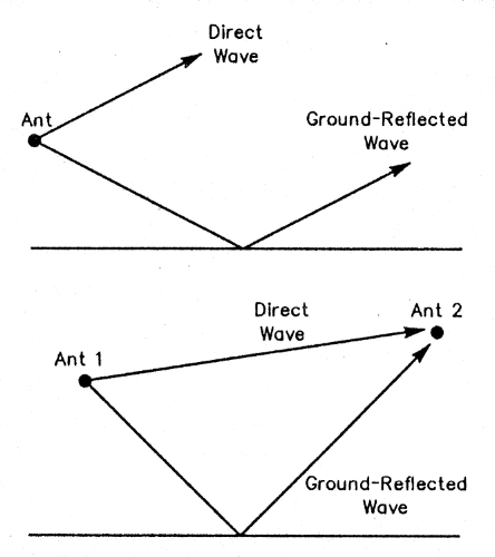
Figure 1- At A, the direct and ground-reflected components of the space wave for ionospheric propagation. At B, the space-wave components for local propagation.
These facts suggest that the first requirement of a receiving antenna with low response to local noise is insensitivity to vertically polarized radiation, the dominant component of the ground wave. Surprisingly, simply avoiding the use of vertical wires isn't enough. An antenna composed only of horizontal wires can still respond to vertical fields.
A Low Dipole
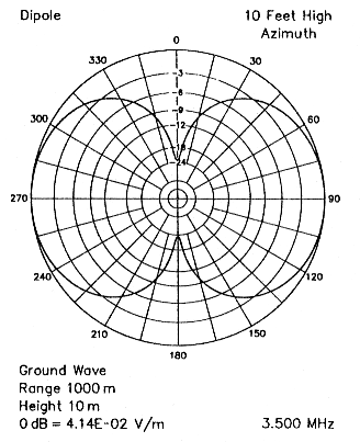
Figure 2-Azimuthal plot of the ground-wave response of a 10-foot-high 80 meter dipole. The input power to the antenna is 1 kW. The peak electric field is shown.
Figure 2 shows the ground-wave response of an 80 meter dipole 10 feet high. An' easy-to-install, inconspicuous dipole like this is sometimes used for receiving when the transmit antenna is vertically polarized. The pattern shows the electric-field strength 10 meters above ground at a distance of 1000 meters for an input power of 1 kW (the dipole exhibits the same pattern on receive). This geometry might be representative of that for a noisy power pole. Although the pattern may look similar to that of a free-space dipole, I think you'll be surprised to know that the wire is oriented broadside to the pattern null. A low dipole actually responds to ground-wave fields best off its ends!
Here's an explanation for this peculiar behavior: The dipole has no response to the vertical component of a broadside ground wave because the electric field is perpendicular to the wire. The antenna responds only to the weak horizontal component. The vertical component also is perpendicular to the mirror image of the antenna formed by the ground-reflected wave. But away from broadside, the dipole, its image, or both, have a nonvanishing projection in the vertical plane. This enables the dipole to respond to the vertical component of a ground wave. In addition, lossy earth causes the surface wave to develop a radial component in the direction of propagation. Away from broadside, the radial component also projects onto the wire and induces current. The vertical and radial components induce maximum current when the surface wave arrives in line with the wire.
When compared to a quarter-wave vertical with four radials elevated 10 feet above ground, the low dipole has a 12.5 dB lower ground-wave response in its most sensitive direction in line with the wire. For sky-wave signals arriving at 20° elevation from their weakest direction (also off the ends), the dipole has 10 dB lower response than the vertical. Therefore, the low dipole has a signal-to-noise ratio advantage of 2.5 dB for signals and noise arriving from their worst-possible directions. In the most favorable directions broadside to the wire, the S/N advantage peaks sharply at 26.1 dB.
Raising the dipole broadens the broadside S/N peak and improves S/N off the ends. For example, for signals arriving at 20° elevation, a dipole at 50 feet has an S/N advantage over the reference vertical of 6.3 dB in line with the wire and 25.6 dB broadside. If you have just a single noise source and you can rotate a high dipole, you should be able to come within a few decibels of the latter figure most of the time. But when multiple noise sources in different directions arise (typical for power-line noise in times of low humidity), rotating the antenna won't help much. The S/N advantage of the high dipole then is likely to be near the worst-case figure.
These numbers illustrate the advantage of horizontal receiving antennas and substantiate the notion long held by amateurs that "verticals are noisy." But you can reduce ground-wave noise much more effectively if you don't rely on a simple horizontal wire.
Canceling Ground-Wave Components
Although a horizontal wire responds only weakly to a broadside ground wave, its response is substantial off the ends. If you could somehow eliminate the end response, you'd be left with the low broadside response and whatever residual response developed at intermediate angles.
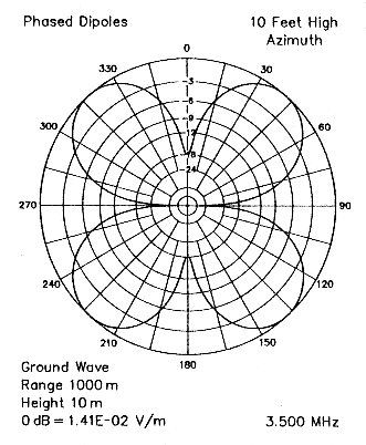
Figure 3-Azimuthal plot of the ground-wave response of two parallel dipoles 10 feet apart, 10 feet high and fed out of phase. The input power to the antenna is 1 kW. The peak electric field is shown.
Figure 3 shows the ground-wave response of two parallel dipoles 10 feet apart and 10 feet high fed out of phase. The phasing cancels everything arriving off the ends of the wires. The end nulls combine with the low broadside response to create a residual cloverleaf ground-wave pattern. The peak of the cloverleaf is 9.3 dB down from the peak end-response of a single dipole.(4) (Wire losses are ignored here to illustrate the cancellation principle.)
This antenna is just a very-close-spaced W8JK endfire array. Although it makes a good receiving antenna for the low bands, it's pretty large. And there's still considerable ground-wave pickup in the cloverleaf peaks. If the wires somehow could remain parallel for all directions, it might be possible to achieve complete cancellation of the vertical and radial components of the ground wave.
In some sense, the sides of a circular loop are parallel everywhere. Current amplitude and phase vary little in small loops of regular shape. Therefore, the currents in opposite sides of such loops are nearly equal and out of phase. Unlike a W8JK array, a small horizontal loop does not have a null anywhere along the ground. But its ground-wave response is uniformly low in all directions because the antenna responds only to the weak horizontal component. Everything else cancels out (or nearly so).
A small loop usually is defined as one with a total conductor length of less than 0.1 a.. But unless you use large-diameter conductors to minimize RF resistance, loops this small are inefficient. A preamplifier may be needed to overcome receiver noise. You can increase the output of a loop by increasing its size, but the larger you make it, the less constant the current becomes. This reduces ground-wave cancellation.
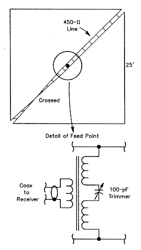
Figure 4-Basic diagram of the 80 meter low-noise loop antenna showing detail of the feedpoint arrangement. The antenna measures 25 feet on a side, is 10 feet high, and made of #14 wire. It's fed at opposite corners with phasing lines made of #14 wire spaced 1.5 inches. A small ferrite transformer at the junction of the phasing lines matches the antenna to 50 Ω coaxial feed line and also functions as a balun. The trimmer capacitor (a capacitance of about 40 pF is required) in series with the antenna-side winding resonates the loop at 3.5 MHz.
The antenna of Figure 4 overcomes this difficulty by using two feedpoints, each on opposite sides of the loop to force current balance. One of the phasing lines is twisted to maintain proper phase.(5) This loop can be made quite large and still exhibit very low response to ground-wave noise.
A Practical Design
The 80 meter loop of Figure 4 has a perimeter of 0.36 X.. It's 25 feet on a side, 10 feet high, and made of #14 wire. It's fed at opposite corners with phasing lines made of #14 wire spaced 1.5 inches. A small ferrite transformer at the junction of the phasing lines matches the antenna to 50 S2 and also functions as a balun. A trimmer capacitor (about 40 pF is needed) in series with the antenna-side winding resonates the loop at 3.5 MHz.
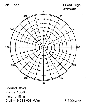
Figure 5-Azimuthal plot of the ground-wave component of a 25-foot-square, 80 meter loop at a height of 10 feet. The input power to the antenna is 1 kW. The peak electric field is shown.
The ground-wave response of this particular loop is shown in Figure 5 and its sky-wave response in Figure 6. For signals arriving at 20° elevation, the worst-case sky-wave response is 20.5 dB below that of the reference vertical. This signal level is quite usable on 80 meters without a preamp. Because the loop reduces ground-wave noise at least 45.1 dB, S/N improvement is 24.6 dB for the worst-case combination of signal and noise directions. If you use a preamp and adjust for equal signal levels, ground-wave noise will be four S units lower on the loop no matter what direction it comes from! For signals arriving at higher angles, S/N enhancement approaches 30 dB.
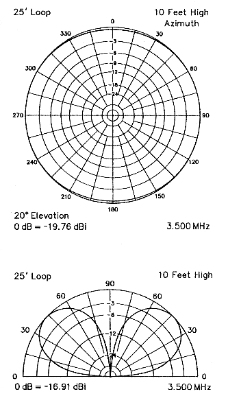
Figure 6-The sky-wave responses of the 10-foot-high, 25-foot-square, 80 meter loop. At A, the azimuthal plot; at B, the elevation plot.
Both the ground-wave noise pattern and sky-wave signal pattern are very uniform in azimuth. The antenna is essentially omnidirectional with an overhead null, just like a vertical. An overhead null is useful for reducing near-vertical-incidence sky-wave signals from nearby stations. (The loop rejects their ground-wave signals along with local noise.)
Although the S/N performance of this loop is not particularly sensitive to height, you can increase output level substantially by raising the antenna well above ground. For example, if you raise the loop to 50 feet, the output increases 15.2 dB for signals arriving at 20° elevation. At this height, the output level is only 5.3 dB below that of the reference vertical. You'll never need a preamp with a loop this high. The S/N advantage drops 0.1 dB. At a height of 20 feet, output increases 7.2 dB and S/N drops 0.6 dB.
You can shrink the loop to 10 feet on a side. The S/N advantage increases 0.5 dB, but the signal level drops 6.5 dB. You can raise the signal level 3.4 dB by doubling the loop side lengths to 50 feet, but the S/N advantage then drops 7.9 dB. You can thus trade-off loop size, S/N enhancement, and signal level. If you use smaller wire, output drops. For example, it's 1.7 dB lower for #22 wire.
Although this loop is a narrowband device and must be carefully resonated, the resonance is much broader than that of a typical small loop. You can get away with a single capacitor setting for both 3.5 and 3.8 MHz if you're willing to accept somewhat lower signal levels. The capacitor setting does not affect the patterns or skywave-to-ground-wave ratio-it simply alters output level.
The input resistance at the junction of the phasing lines varies over a wide range with loop size, height, and phasing-line characteristic impedance. The input resistance is about 40 S2 for the loop of Figure 4 at a height of 10 feet. A transformer using a type-77 ferrite core (such as an FT-82-77, FT-114-77 or FB-77-1024) with 9 turns of any size enameled wire on the coax side and 8 wire turns on the antenna side provides a good match to 50Ω coax. The input resistance drops to about 20 Ω when the loop is raised to 20 feet and to about 15 Ω at 50 feet. Use 13 turns of wire on the coax side for 20 feet and 15 for 50 feet.
Although the optimum transformer turns ratio varies with antenna height, little output is sacrificed if you use a fixed ratio. For example, output is only I dB less than optimal when a loop designed for 10 feet is used at 50 feet. If you're determined to obtain the best possible match, use 16 turns of wire on the coax side and tap the winding for lowest SWR (alternatively, a switch can be used to select any of two or more taps). Use the lowest possible power when measuring SWR. It's easy to puncture the dielectric of a small trimmer capacitor with a momentary blast.
The antenna's resonant frequency shifts when the phasing lines get wet. If you use true open-wire line with plastic spacers, the frequency shift will be less than 100 kHz. But if you use 450 Ω line with segmented polyethylene dielectric, the resonant frequency decreases more than 200 kHz when the line becomes thoroughly damp. Although this won't affect signal-to-noise ratio, output drops in the desired frequency range. You may be tempted to try phasing lines of 300 Ω twinlead routed inside PVC tubing to avoid moisture effects, but line impedances this low work only for smaller loops.
This antenna should be constructed as symmetrically as possible to maximize cancellation of the vertical and radial components of the ground wave. Make the loop perfectly square and accurately align it in the horizontal plane. Cut the phasing lines to the same length. Although these loops perform well near houses, fences, and towers, try to install the antenna as far from other conductors as possible to maximize current balance. Use the shortest possible leads to interconnect the matching components. Although it's probably unnecessary, I like to split the antenna-side transformer winding and put the tuning capacitor in the center to promote equal currents in the phasing-line conductors.
To minimize the number of supports, a loop about 17 feet on a side can be constructed using a 20 meter quad spreader. You can mount the spreader well up on a tower to increase output. Alternatively, you may be able to eliminate supports altogether by stringing a loop in your attic or garage. However, the current balance of indoor loops may be degraded by electrical wiring, plumbing, heating ducts, or other nearby conductors.
On-the-Air Performance
Ed Andress, W6KUT, located in the San Diego surburb of Poway, constructed a loop 21 feet on a side and 10 feet high. Ed describes his antenna in an article starting on page 37. Ed's location is subjected to strong, chronic power-line noise. On 80 meters, Ed uses a pair of phased quarter-wave verticals for transmitting. We used the verticals as a reference when evaluating the loop. A 20-dB preamp was available. With the preamp, signals near loop resonance were about equal to those from the verticals.
The loop performed as expected. It dramatically enhanced the signal-to-noise ratio of most sky-wave signals. Sometimes the verticals did better during a momentary change in propagation; occasionally a particular noise arose that the loop didn't attenuate much. But overall, the loop was far superior. It made little difference on strong signals. It made listening to moderately strong signals much more pleasant. It let us copy weak signals that were buried in the noise and unreadable on the verticals.
During times of no detectable power-line noise, we often noticed a curious effect: The loop still enhanced signal-to-noise ratio by one or two S units, making copy of moderately weak signals more pleasant. On these occasions, we were unable to hear the telltale, raspy buzz of power-line noise (or any other noise signature) when we listened with the transceiver's AM detector. Unless noise happens to arrive at low angles and signals at high, there's no reason for the loop to enhance sky-wave S/N. We believe that the unidentified noise is local and propagates by the ground wave. We speculate that it may be the sum of hundreds of weak man made noise sources in the densely populated suburb. (The superposition of a large number of noise sources tends to be characterless even when the individual sources aren't.)
Total Ground-Wave Cancellation
If you stack two of these loops vertically and bring both feed lines into the shack, you can form a deep null on the horizon for all azimuth angles by combining the signals with a fixed amplitude and phase offset. Except for azimuth-response irregularities caused by nearby conductors and small elevation-angle differences due to range, this system will cancel all ground-wave components. This noise canceler was to have been the original subject of this article. However, a single component loop worked so well in practice that I decided total ground-wave cancellation was overkill.
Comparison with Other Antennas
A conventional, single-feedpoint, small loop about two feet on a side - oriented horizontally - yields roughly the same S/N enhancement as the loop of Figure 4. However, output will be down about 46 dB from the reference vertical. You'll need a low-noise preamp with a loop this small unless your receiver has a very low noise figure. Still, even with a preamp, a conventional small loop makes an attractive, low-profile alternative. You must construct a low-output antenna like this carefully to avoid stray pickup. A single capacitor setting won't provide good output levels on both phone and CW.
The WA2WVL cardioid antenna attenuates thunderstorm static and ground-wave noise to the rear. If you're seldom troubled by omnidirectional local noise, it shouldmake a more effective receiving antenna than the loop described in this article. The cardioid also requires fewer supports and less space. As a bonus, it's inherently broadband.
If you have room for a two-wavelength Beverage, it will outperform the WA2WVL cardioid on sky-wave noise and should reduce ground-wave noise arriving more than 45° off boresight by at least 15 dB. If local noise near boresight isn't a problem, a long Beverage can tremendously improve your receiving capability.
The easiest way to improve reception on 80 or 160 meters is to use the most sensitive horizontal antenna available at your antenna switch. Many hams with 80 meter verticals find that switching to a 40 meter dipole or beam improves copy of weak signals even though the antenna is nowhere near resonant on 80 meters. When just a single noise source is active, you should be able to null it by broadsiding a 40 meter rotary.
Scaling the Antenna to Other Frequencies
While I've used the 80 meter band for illustration in this article, it's easy to scale the design to other frequencies. Simply multiply lengths, heights, transformer turns and capacitor values by the number you get when you divide 3.5 by the target frequency in MHz.
That said, I don't recommend this antenna for use above 40 meters. If you're using a vertical antenna on the upper HF bands, do yourself a favor and replace it with the highest horizontally polarized antenna you can manage. Not only will your receive noise decrease, your transmit signal almost certainly will improve due to higher ground-reflection gain.? (Exception: If your vertical radiates over saltwater, keep it!) If you're already using a horizontal wire on upper HF, I think your next antenna project should be a rotary beam rather than a receiving loop.
Notes
- Floyd Koontz, WA2WVL, "Is this Ewe for You?" QST, Feb 1995, pp 31-33.
- Frederick Terman, Radio Engineers' Handbook, 1st ed (New York: McGraw-Hill, 1943), pp 674-709.
- MININEC-based antenna-analysis programs do not compute the surface wave, nor can they accurately model antennas close to ground. I used NEC/Wires 2.0 with its surface-wave and Sommerfeld-Norton ground options for all antenna models in this article. All models assumed average ground characteristics (dielectric constant 13, conductivity 5 mS/m).
- A small cloverleaf peak requires very close wire spacing. For example, the peak is down only 5.4 dB for a spacing of 50 feet.
- The feed arrangement is like that of an Alford Loop. In fact, the low-noise receiving antenna really is just a variant of the VHF/UHF loop devised by Andrew Alford for a different purpose in 1940. See Terman, pp 814-815.
- Don't be tempted to eliminate the transformer and connect 50-Ω coax directly to a loop. The transformer functions as a current balun. It keeps noise current induced on the coax shield from entering the receiver. Just a little pickup by the shield can pollute the low-noise output of a loop.
- For example, on 20 meters, a horizontal dipole only 35 feet high has 3 to 6 dB broadside gain over a vertical dipole at low angles over average ground.
K6STI