Another way to stack VHF/UHF yagis
An unusual stacking geometry maximizes array gain and minimizes side lobes.
Yagi-Uda arrays are wonderful Y antennas. Invented by Shintaro Uda in collaboration with Hidetsugu Yagi in the 1920s,(1) no other antenna yields so much benefit for so little complexity in so many practical applications.(2) Yagis are easy to design, offer significant gain over simple antennas and are capable of highly directional patterns.
One of the more attractive properties of a Yagi is that it's easy to obtain higher performance by simply increasing its boom length and adding some elements. (For optimum results, however, you need to readjust all the element lengths and spacings when you resize a design, but this is easy to do with a computer using automatic optimization algorithms.)(3) There's no limit to the increase in gain and pattern quality made possible by lengthening the boom - no theoretical limit, that is Once your Yagi becomes so long that it's mechanically infeasible to further increase the boom length, what do you do? You stack multiple Yagis, of course!
Stacking refers to the simultaneous excitation of a number of similar antennas. The term comes from the appearance of antennas arrayed above one another in the vertical plane. You can stack Yagis vertically, horizontally, or even in depth. If you space the individual antennas properly, the overall gain increases 3 dB(4) each time you double the number of antennas in a free-space array.(5) So, when your Yagi becomes unmanageably long, you simply replicate it - and make your antenna unmanageably high and wide, too!
The Stacking trade-off
When you stack a pair of Yagis, not only does the gain increase, but the width of the forward lobe decreases in the stacking plane.(6) Figure 1 shows the E-plane pattern for an 8-element, 12-foot Yagi optimized for high performance at the low end of the 2-meter band.(7) This is the azimuth pattern when the Yagi is oriented for horizontal polarization. Figure 2 shows the pattern for a pair of these antennas stacked horizon tally with 150 inches between the booms. This spacing maximizes forward gain for this particular design.
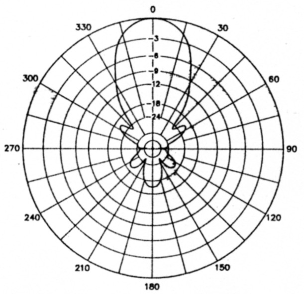
Figure 1 - Free-space, E-plane pattern for an optimized, 8-element, 12-foot-boom, 2-meter Yagi. Freq: 144.2 MHz; 0dB=11.30dBd
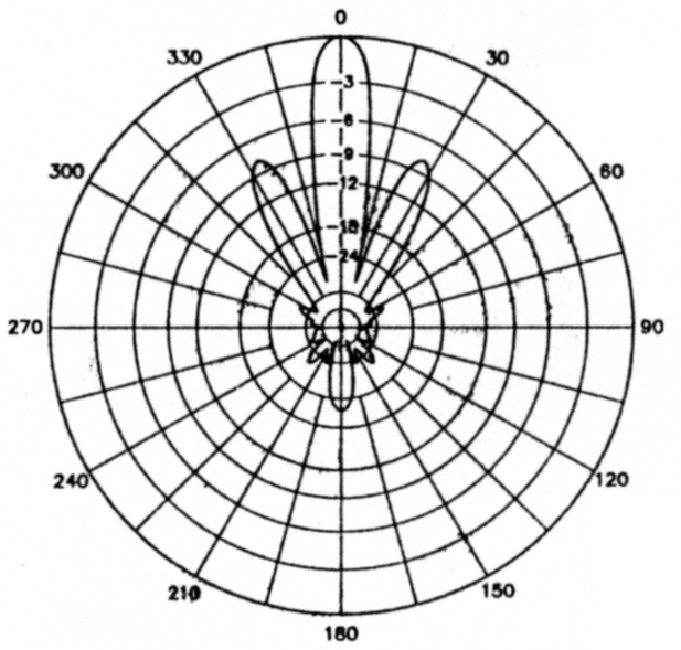
Figure 2 - Free-space, E-plane pattern for a pair of 8-element Yagis stacked in the E-plane for maximum forward gain. Freq: 144.2 MHz; 0 dB = 14.38 dBd
Figure 2 illustrates the fundamental design trade-off for stacked arrays. Although stacking increases the array's forward gain and narrows the main lobe, it also creates 'a pair of large side lobes just beyond the main lobe. In this particular case, the side lobes are down only 7.5 dB from the main lobe. The side lobe level is 2 to 3 dB greater than the response of a single Yagi in the same region. This makes the stacked pair more sensitive to noise and QRM just beyond boresight (off the axis of the main lobe). Even worse, the side lobes make it much more difficult to peak the array on a received signal, especially when it's fading.
You can obtain a better pattern by reducing the stacking distance and surrendering some forward gain. Figure 3 shows the azimuth pattern for the Yagis stacked 107 inches apart. The gain has dropped 0.36 dB, but the first side lobes are now down 15 dB from the main lobe. For most applications, this is a reasonable performance compromise. If you can tolerate less gain, you can drop the side lobes further by decreasing the stacking distance even more.
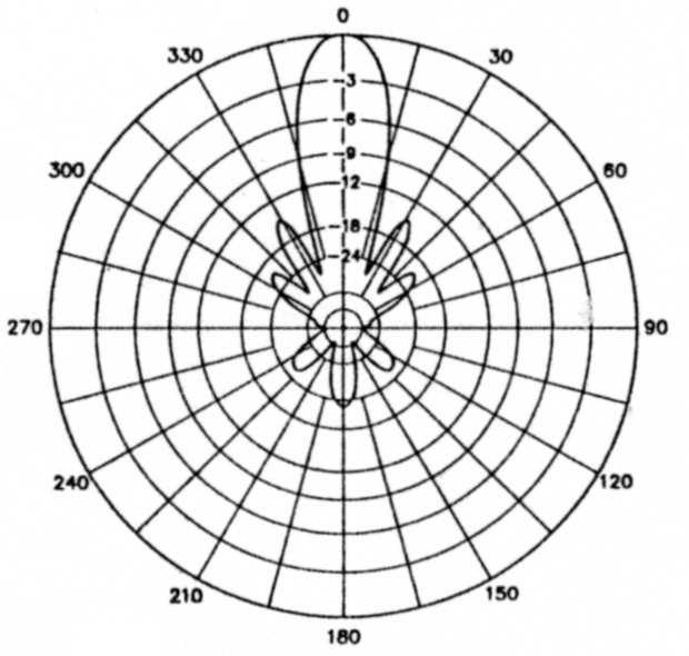
Figure 3 - Free-space, E-plane pattern for a pair of 8-element Yagis stacked in the E-plane for reduced side lobes. Freq: 144.2 MHz; 0 dB = 14.02 dBd
The Four-Stack
Many hams use a rectangular stack of four Yagis for serious weak-signal work on VHF/UHF (see Figure 4). This configuration uses two Yagis spaced horizontally with a second pair stacked directly above the first. Two vertical masts joined at their centers by a horizontal spreader support the array. This support structure is called an H frame. (For better stability, large arrays often use two horizontal spreaders displaced vertically).
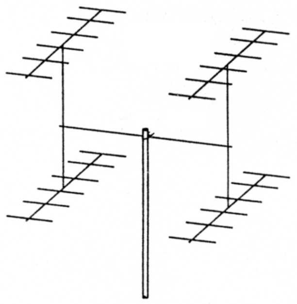
Figure 4 - Stacking arrangement for a conventional Yagi four-stack.
The horizontal and vertical stacking distances most often are chosen to force the first side lobes in each plane to be 12 to 18 dB below the level of the main lobe. Figures 5A and 5B show the E and H-plane patterns for a four-stack using the Yagi of Figure 1, with the first side lobes down about 15 dB. The horizontal stacking distance is 107 inches and the vertical stacking distance is 99 inches.(8) This four-stack has 5.54-dB gain over a single antenna and reasonable E and H-plane patterns.
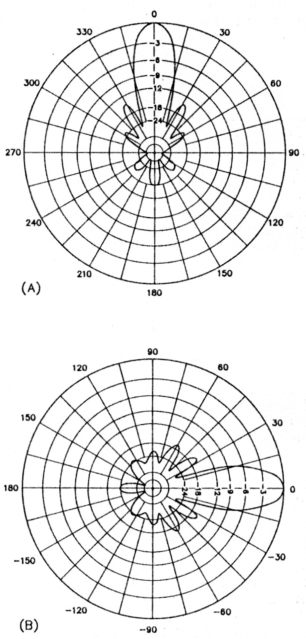
Figure 5 - Free-space, E- and H-plane patterns (A and B, respectively) for a conventional Yagi four-stack. Array spacing is adjusted so that the first sidelobes in each plane are down about 15 dB from the main beam. Freq: 144.2 MHz; 0 dB = 16.84 dBd
The Diamond Stack
The pattern of a stacked array can be factored into two components. The first component is called the antenna factor and is simply the pattern of a single array element - in this case, an individual Yagi. The second component is called the array factor and depends only on the stacking geometry, not on the individual antennas comprising the array. Without significant mutual-impedance interactions among individual array elements (the usual case at VHF/UHF), the pattern for the array as a whole is simply the product of the antenna factor and the array factor.
The array factor accounts for the undesirable side lobes of stacked Yagis. If you express the array geometry as a sequence of current magnitudes that correspond to the excitation of individual array elements, the array factor is simply the Fourier transform of the sequence. For the Yagi four-stack, the current sequence in either plane is 1-1. This notation indicates that the two Yagis are excited with equal current magnitudes. The Fourier transform of a uniform sequence like this is proportional to (sin x)/x, where x is related to the angle from boresight. The first peak in this function for x > 0 corresponds to the undesirable first side lobes in a Yagi four-stack.
Signal-processing experts will tell you that a uniform sequence like 1-1 yields just about the worst-possible Fourier side lobes.(9) The way to lower side lobe levels is to use a tapered sequence. For example, the Fourier transform of a 1-2-1 sequence is the transform of a 1-1 sequence squared. A side lobe that's down n dB for a 1-1 array is down 2n dB for a 1-2-1 array of the same spacing. The theoretical trade-off is that the width of the main lobe broadens when you taper a sequence. The practical trade-off for a 1-2-1 is that an additional Yagi is required and you have to figure out how to excite it with twice the current.
Or do you?
Take a Yagi four-stack and rotate it 45° so that the array looks like a diamond in- stead of a square - keep the Yagis horizontal. What's the sequence of excitation currents in the horizontal plane? From left to right, we have a single Yagi, then two, and finally one. All the Yagis are in phase, so the current contribution from the center Yagis is twice that of the end antennas. In the horizontal plane, the current sequence is 1-2-1, and we should expect much lower side lobes! The original side lobes are still there, of course, but they're pointing harmlessly up in the air and down at the ground instead of at the horizon.
Now you can aggressively expand the spacing between Yagis to increase array gain. Figure 6 shows a diagram of the array. Figures 7A and 7B show the E and H-plane patterns for the stacking distances that maximize forward gain. The gain of the diamond array is 0.78 dB greater than that of a conventional four-stack, and the first side lobes have disappeared completely, leaving a second set of side lobes 26 dB down at 60° azimuth! The head-on, 3-D patterns in Figure 8 show the side lobe locations for conventional and diamond stacking.(10)
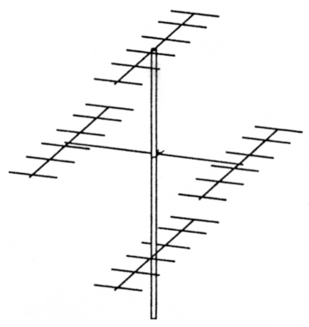
Figure 6 - Arrangement of a diamond stack of four Yagis.
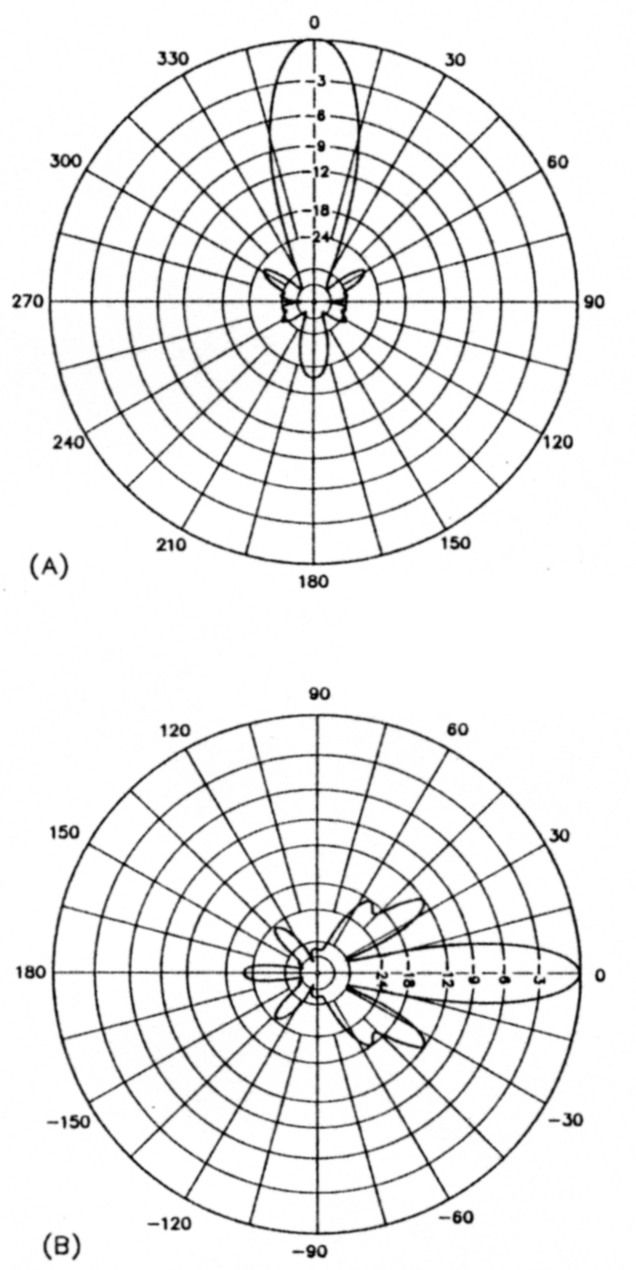
Figure 7 - Free-space, E- and H-plane patterns (A and B, respectively) for a diamond stack of four Yagis. Array spacing is optimized for maximum forward gain. Freq: 144.2 MHz; 0 db = 17.60 dBd
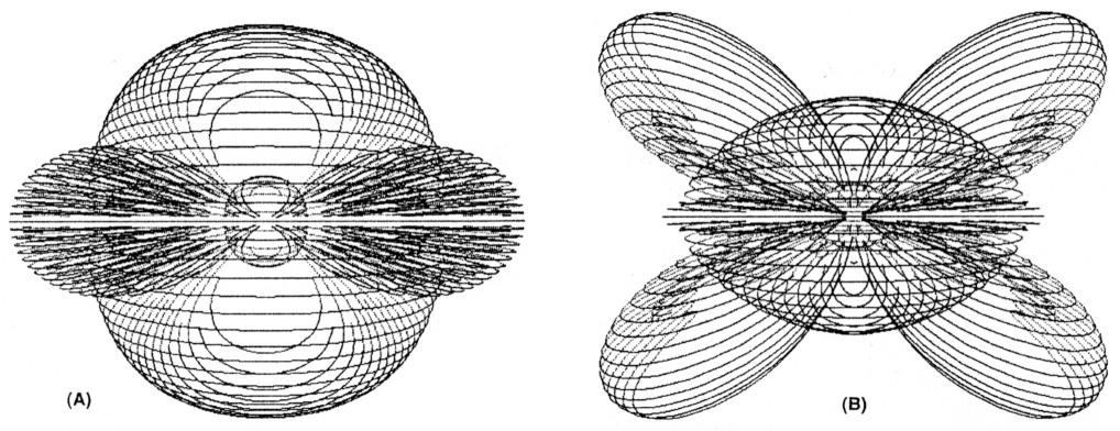
Figure 8 - Head-on views of the 3-D patterns of a conventional Yagi four-stack (A) and a diamond stack (B) of the same antennas. Array spacing is the same as for Figures 5 and 7. The large, central blobs are the main beams, the small spheres are the back lobes, and the ovals are the first side lobes. Freq: 144.2 MHz; At A, peak = 16.84 dBd; at B, peak = 17.60 dBd
The Bad News
For terrestrial use, a diamond configuration of four Yagis significantly outperforms a traditional square. But when you physically examine the array, you'll begin to appreciate the construction difficulties.
For the 12-foot Yagi used as an example, the optimum boom spacing for the diamond array is 238 inches vertically and 151 inches horizontally. To support this array, you'll need a heavy-duty, 25-foot vertical mast that extends a few feet into your tower, and a beefy, 12.6-foot horizontal spreader. In contrast, the booms of a conventional four-stack are spaced only 8.5 feet vertically and 9 feet horizontally. By contemporary VHF/UHF standards, the Yagi I've used as a building block in this article has a short boom. The stacking distances must be even greater for longer Yagis with higher gain.
Furthermore, you'll need to use an insulated section for the last few feet of horizontal spreader to avoid detuning the left and right Yagis. For the same reason, you'll need to drop their feed lines vertically for some distance rather than running them up the boom and back along the spreader. If you're using short Yagis, consider mounting them at the rear of the boom. When mounted this way, run the feed lines back along the booms and spreaders. Although unbalanced, this support method removes extraneous conductors from the array near-field, does not require insulated spreaders and keeps the feed lines tied down.
Conclusion
If you're not daunted by the construction difficulties, a diamond configuration of four Yagis offers significant performance advantages for terrestrial work when compared with a conventional square array. Above 2 meters, the diamond configuration becomes much more manageable physically. Basically, it allows you to squeeze the maximum possible performance from four Yagis. As a final bonus, the distance between Yagis is greater in an optimized diamond configuration. This reduces any residual mutual interaction between the individual antennas.
Notes
- John Kraus, Antennas (New York: McGraw-Hill, 1988), second edition, pp 481 to 482.
- Actually, the number-one antenna of all time for simplicity, effectiveness, and practicality has got to be the ubiquitous whip. But if we restrict our attention to directional antennas, the Yagi gets my vote.
- Steve Powlishen, K1FO, has developed VHF/UHF Yagi-design families that require only a simple element-length correction as elements are added. See recent editions of The ARRL Antenna Book or The ARRL Handbook. (See the ARRL Publications Catalog elsewhere In this issue. - Ed.)
- When stacking small Yagis in the H plane, it's possible to obtain somewhat more than 3-dB gain due to favorable mutual-impedance interactions between the antennas. For example, you can get 3.8-dB stacking gain from a pair of two-element Yagis in free space if you stack and tune them just right.
- This stacking-gain formula also applies at VHF/UHF when the array is many wavelengths above ground. Unfortunately, it doesn't apply for HF Yagis at typical installation heights. The elevation patterns for HF Yagis at different heights aren't very similar and don't reinforce well. For more Information, see "Stacked Yagi Arrays: Fact and Fiction" by Dave Pruett, K8CC, in NCJ, Jul/Aug 1991, pp 18-20.
- The pattern in the other plane remains unchanged unless mutual impedances between the antennas alter element currents.
- I optimized this antenna for maximum forward gain and a good E-plane pattern with YO 6.5. I used AO 6.5 to optimize stacking distance for all stacked arrays in this article. (VO and AO are available from Brian Beezley, K6STI, 3532 Linda Vista Dr, San Marcos, CA 92069; tel 619-599-4962; each program is $60. See his ad elsewhere in this issue. - Ed.)
- For equal side lobe levels, the stacking distances must differ somewhat in the two planes because Yagis have different E and H-plane patterns.
- The only thing worse than a 1-1-1-1 sequence, for example, is a 1-0-0-1 sequence. This amounts to disconnecting your feed line from the innermost Yagis!
- Dick Knadle, K2RIW, built and used diamond stacks of Yagis in the late 1970s and described them at several VHF conferences, although he never published his designs.
K6STI, Brian Beezley.