A ground-coupled portable antenna
As the saying goes, "Imitation is the sincerest form of flattery". Here's a homebrewed antenna that proves the point.
This homebrew portable antenna for 40 through 6 meters is patterned after the ground coupled design pioneered by Alpha Delta Communications, Inc.(1) Instead of using radials, this antenna employs a simple and very small grounding system that needs no tuning.
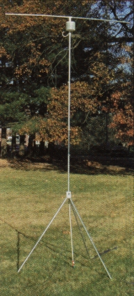
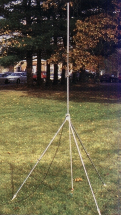
The antenna described here is a quarter-wave vertical sitting on a tripod base. The vertical mast and the tripod are each made of 2 foot long telescoping sections of 3/4 and 1/8 inch diameter aluminum tubing.(2) The mast itself resonates on 10 meters, lightweight aluminum tubing sections are added to the top of the mast to tune the antenna to 12, 15 and 17 meters.(3) These added tubing lengths can be installed vertically or horizontally. The antenna is fed at the top of the tripod, making the base a part of the radiating system. A bungee cord stretched from the top of the tripod to a stake in the ground keeps the structure stable.
Beneath the foot of each tripod leg is a grounding strip 2.5 inches wide and about 3.5 feet long, made of aluminum tape.(4) These strips are simply laid en the ground and form one plate of a capacitor coupling RF from. the antenna to the ground. That's the whole grounding system! When I read about this in QST (l), I was skeptical, but intrigued. The arrangement is similar to that of a mobile antenna system in which the car body acts as one plate of a capacitor coupling RF to the road and ground. This grounding system work. The antenna radiates well and the SWR is reasonably low on all bands.
(The tripod and grounding strips can also be used with any vertical element or mobile whip you have.) A loading coil added between the aluminum tubing mast and the flattop permits operation en 20, 30 and 40 meters. With the coil positioned this far up the anterma, the entire 10 feet of tripod and mast are unloaded radiators on all HF bands.
Building the tripod
The top of the tripod, makes it easy to set up. The three 5/8 inch diameter x 0.058-inch-wall aluminum tubes extending from cap are permanently assemble the tripod, the legs slide over these tubes. A 3 inch long, 3/8-inch carriage bolt passes a hole in the, top of the PVC cap to support the vertical element. This bolt also grips the 4 inch long aluminum tubes inside the cap to form the three sloping legs of the tripod. See Figure 2 and its caption for details on how to make this top cap.
A 50 Ω coaxial feed line attaches to the antenna via an SO-239 chassis connector mounted on a aluminum angle bracket at the top of the PVC cap (see figure 1). Make a 5/8 inch diameter hole in the bracket to accept the coax connector boddy; you'll also need to drill four small holesfor the connector's mounting srews. The 3/8 inch bolt through the top of the cap keeps the aluminum bracket in place.
To assemble the tripod top, invert the cap so that you are looking down at the open end. Insert the carriage bolt through the 3/8 inch hole in the cap, through the mounting hole in the aluminum angle and add a lock washer and nut to the bolt. Initially, thread the nut about an inch onto the bolt so that the bolt is still loose and its head is out of the cap. Insert the three aluminum tube into the slots in the wall of the cap and down against the carriage bolt where it passes through the hole in the cap. Tighten the nut so that the carriage bolt head sqeezes the tubes outward and into the slots. Once the nut is hand thight, wriggle each tub to seat it snugly with its tip into the countersunk hole with the bolt. Tighten the nut until the round wall of the cap is slightly deformd into a triangular shape.
Each tripod leg consists of a 0.058 inch wall, 3/4 inch diameter tube and a 0.058 inch wall, 5/8 inch diameter tube that fits inside the 3/4 inch tube. Each tube is two ffeet long; three can be made from 6 foot tubing lengths. Dimple each 3/4 inch tube about one inch from each end. The dimple acts as a stop and prevents the smaller tube from penetrating any farther. Form the dimples using a couple of firm hammer taps on a center punch placed against the tube. When joining the tubes, push a bit when inserting the smaller tube so that the side of the dimple holds the smaller tube in place.
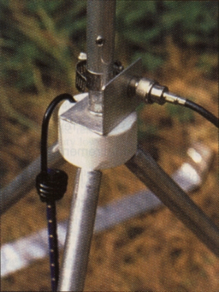
Figure 1 - The top of the tripodwith the bottom section of the mastconnected to it. A bolt holds the the three legs supports in the PVC cap slots. This bolt also passes through the 1,5 x 1,5 inch aluminium angel piece that supports an SO-239 chassis connector for feedline connection. A 1/4 inch hole in the cap top accepts the bungeecord hook.
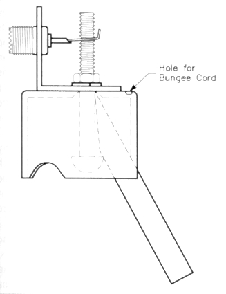
Figure 2 - The tripod top cap. The three 5/8 inch diameter aluminum tubes are 4 inches long, cut at a 30° angle at the end within the cap. From inside the cap, countersink a 3/8 inch hole in the cap top.
This forms a trap that holds the ends of the aluminum tubes. Although only one of these leg supports is shown, all three are held between the bolt head, the three slots (either carved or flied in the wall of the cap) and the countersunk hola in the cap top. The slots in the cap are about 3/8 inch deep and wide enough to receive the aluminum tubes. An easy way to lay out the slots is to use the fluted handle from en outdoor water faucet as a template. The handie fits nicely against the cap and has six flutes about the circumference allowing you to mark three equally spaced locations.
Ground strips
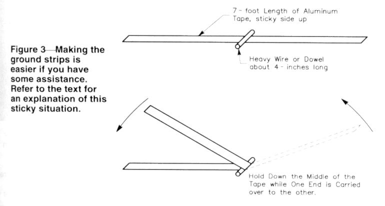
Although mating two strips of aluminum tape with their sticky sides together might seern like a routine job, it's probably the most difficult part of building this antenna! The adhesive is quite sticky and unforgiving, and handling the long strips can be messy. Get an assistant to help you with this task. You'll need three strips.
See Figure 3. Cut a 7 foot length of tape frorn the roll and lay it down, sticky side up, on the floor or a large table. Have your helper press a piece of heavy (#12) solid wire or a thin dowel across the width of the strip at the 3.5 foot midpoint and hold it in place. Pick up one end of the strip and carry it over the midpoint, keeping it tight so that it doesn't sag and touch the lower half. Keep both ends of the strip aligned while your helper at the midpoint presses the top piece of tape against the lower, working their way toward you. Trim (or remove) the excess wire or rod and the ground strip is done. Don't worry if the strips aren't aligned perfectly.
The mast
The 8 foot mast is made frorn two telescoping 3/4 and two 1/8 diameter x 0.058 inch wall aluminum tubing sections. Slot the ends of the 3/4 inch tubes so that they can be tightened around the smaller tubes with hose clamps.(5) To insulate the bottom 1/4 inch section from the 1/8 inch bolt in the tripod that supports the mast, its lower end is equipped with a plastic insulator. As shown in Figure 4, the insulator is a 2 inch length of acrylic tubing. The lower end of the acrylic tube extends about a quarter inch below the aluminum tube and is slotted so that the mast can be tightened around the bolt. Drill a 5/32 inch hole through the upper end of this insulator and the aluminum tube to pass a #6-32 bolt and nut to hold the insulator in place.
After mounting the SO-239 coax connector on the aluminum angle strip, solder a 2 inch length of # 14 bare solid copper wire to the connector's center terminal and bend it close to the 3/8 inch bolt in the tripdre top. Then bend the wire up and parallel to the bolt and about a quarter inch from it. When the bottom section of the mast is placed over the bolt, place this wire between the aluminum tube and a hose clamp. As you tighten the clamp, it makes the electrical connection from the coax to the mast and squeezes the slotted aluminium tube and insulator tightly agains the bolt.
With the mast on the tripod, an easy way to make frequency adjustments is to separate the mast from its bottorn section and lower it to the ground. You can then reach the flattop, and coil without tilting the mast. For this reason, I don't tighten this joint. 1 place, a #6-32 bolt through the 5/8 inch tube which is the second section of the mast, about one inch from its lower end so that it doesn't slide very far in. I still use a hose clamp over the 3/4 inch tube, adjusting it to make a snug sliding fit for the upper mast.
For the top antenna sections, I use 5/8 inch diameter thin walled aluminum tubing used for aluminum clothes poles. This material ik lighter and cheaper than the 0.058 inch wall tubing used for the tripod and mast, hut is strong enough. Short tubing sections can be joined together using 2 inch long sleeves made from the 3/4 inch diameter x 0.058 inch wall aluminum tubing. You need two 2 foot, two 1.5 foot and two 1 foot lengths of the 5/8 inch thin walled tubing, three couplings and a T joint to connect the flattop to the mast or the top of the coil. See Figure 5.
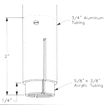
Figure 4 - An acrylic (Plexiglas) tube insulates the mast from the 3/8x3 inch bolt that supports it. The tube has a 3/8 inch ID and 5/8 inch OD so that it slips over the supporting bolt and telescopes inside the lower 3/4 inch mast section. Both the aluminum tube and the insulator tube are slotted using a hacksaw so they can be tightened around the bolt with a clamp. To mount a mobile antenna on the tripod, cut a 2 inch length of 1 inch diameter acrylic rod and drill end tap one end to accept the 3/8x16 coarse thread bolt of the tripod and 3/8x24 fine threard at the other end for the base of a mobile whip.
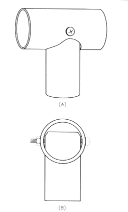
Figure 5 - A T is needed to make the flattop. The 3/4 inch diameter horizontal tubing has a 0.058 inch wall and accepts the 5/8 inch diameter thin wall tubes. The 5/8 inch diameter vertical piece has a 0.058 inch wall end fits into the 3/4 inch tube at the top of the cole form. To make a 5/8 inch hole in the 3/4 inch tube drill a hole then expand it with a 5/8 inch diameter or larger countersink. (This process is heavy work for a countersink, so use a little lubricating oil.) Before drilling a 7/64 inch hole for a #6-32 bolt through the T, assemble the two pieces end squeeze them together tightly in a vise, making them perpendicular. To mount a flattop on the mast without the coll, first place a 3/4 inch diameter coupling sleeve over the 5/8 inch diameter top of the mast end fit the T into that coupling.
Bungee tie-down
The antenna is quite light, and even with the wide base of the tripod it needs to be stabilized against wind gusts or someone tripping over the coax feed line. A bungee cord and a ground stake do an excellentjob. The top of the tripod is about 3 feet high, so a 1/2 to 3/8 inch diameter, 24 inch long bungee cord works well. Any tent stake will do; drive it into the ground at an angle so it doesn't pull out easily. A special stake shaped like a large screw is ideal for this application.(6) It threads into the ground by hand and has a very low profile. (I leave the stake in the ground and my lawn mower doesn't even come close to striking it.) The stake won't go into hard, baked soil, however. For stability in such locales, or on pavement, hang some bricks, a rock or a jug of water beneath the tripod on the bungee cord.
| Band (meters) | Lenght of flattop (ft) and number of sections | Lenght of vertical top (ft) |
|---|---|---|
| 10 | 0 | 0 |
| 12 | 1 × 2 | 1.5 |
| 15 | 2.5 × 2 | 3.5 |
| 17 | 3.5 × 2 | 5.5 |
Antenna operation on 10 through 17 meters
For 10 meter operation, set up the tripod and place one end of a ground strip under each tripod foot. The ground strips may be laid in any direction. Adjust the mast to a length of about 7.4 feet. This length is quite a bit less than a quarter wavelength and I believe it's because of its closeness to the ground and the thickness of the tripod. No top hat is used on 10 meters. Adjust the mast length to resonate the antenna at your desired 10 meter frequency.
Table 1 provides lengths for the thin wall tubes that you add to the antenna, either as a flattop or a vertical, for operation on 12, 15 or 17 meters. No change to the ground system is needed when changing bands. Table 1 assumes that you will leave the mast set for 10 meter operation. This simplifies band changing, such as moving from 10 meters to 15 meters and returning to 10 meters. These changes are quickly made by just adding the tubing lengths for 15 meters and removing them to return to 10 meters; no measurements, no tools.
6 meter antenna operation
For 6 meter operation, the tripod must be insulated from ground and the mast reduced to a length of 52 inches from tripod to tip; see Figure 6. No ground coupling strips are needed. Simple insulators can be made from 1/2 inch PVC pipe and ouplings.
Cut three lengths of pipe about 4 to 6 inches long and hammer each into a coupling. Cementing them isn't necessary; they will be a tight fit. The other side of the coupling fits well over the 5/8 inch diameter aluminum tubing leg. Adding these insulators to the tripod resonates the antenna in the 6-meter band with good SWR. You can change the operating frequency by adjusting the length of the mast only you don't need to adjust the size of the tripod.
Figure 6 - Here, the antenne is set up for use on 6 meters. The tripod construction remains the same, using logs approximately 4 feet long, but the mast has been shortened. No ground strips are needed and the legs are insulated from ground by 1/2 inch CPVC pipe extenslons at their feet.
Building the loading coil
For operation on the 20, 30 and 40 meter bands, a loading coil must be added to the antenna. A large tapped coil is shown in Figure 7; it tunes the antenna to 20, 30, or 40 meters and permits you to tune to the higher frequency bands without changing the lengths of the top hat. The coil has 13 turns of #8 aluminum wire wound on a 4 inch styrene pipe coupling.(7)(8) This coil form is secured to a 7 inch long, 1/2 inch diameter CPVC pipe using l.25 inch long, #6-32 brass or stainless steel machine screws and nuts. I like to reinforce the 1/2 inch pipe by hammering a 2 inch length of 1/2 inch wood dowel into each end. This allows me to tighten the nuts and bolts without flattening the pipe. These bolts also secure the ends of the 13-turn coil. Using a marking pen, I made black marks on the coil to identify the fifth and tenth turns. The marks serve to locate the proper tap points without having to count coil turns each time.
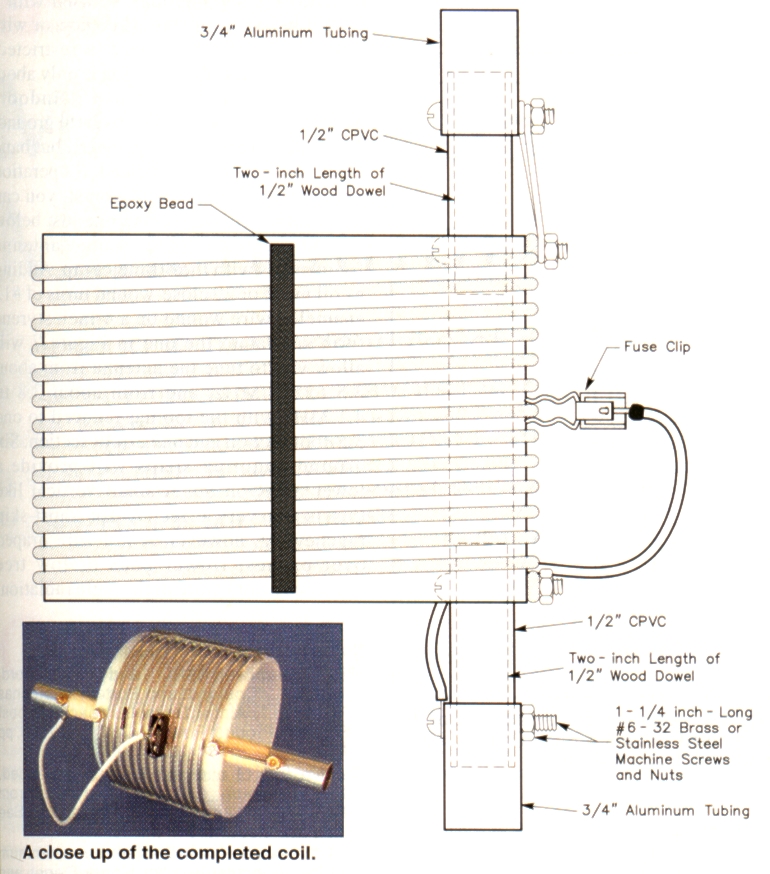
Figure 7 - To make the loading coil, 13 turns of heavy aluminum wire are spaced to fill the form. Secure the coil ends using the same bolts that hold the plastic pipe inside the 4 inch styrene coil form. Mount the coll on the mast with a 3/4 inch diameter aluminum sleeve at the bottom of the plastic pipe; the tap wire is also connected here. An identical sleeve at the top of this plastic pipe connects to the thin tubing for the top vertical section, or to en aluminum T to hold the flattop.
Inside the styrene coil form is a ridge. Use a chisel or file to remove about a 1 inch long section of this ridge to allow the CPVC pipe to lie flat against the inside of the form. Dril 7/64 inch holes at the ends of the styrene coil form and through the 1/2 inch pipe, then bolt them together as shown in Figure 7. Take a 16 foot length of aluminum wire, bend a loop at one end of it, attach the loop to one of the bolts and wrap the form as neatly as possible with 13 turns of wire, without bends, spacing tbc turns to fill the form. Wrap the end of the 13th turn around the bolt at the other end of the coil form, and cut off the excess wire.
To tighten the wire on the form, clamp the form in a vise, grab the coil turns between both hands and progressively rotate the coil from one end to the other several times. This makes the turns tight enough to stay in place as you even out their spacing. To hold the turns in place permanently, run three ribs of epoxy the length of the coil. Use metal/concrete epoxy which has black resin and white hardener, making a dark gray mix that is easy to see against the white background of the coil form. One of these ribs is visible in Figure 7. To make nice straight ribs, first place strips of tape on each side of an intended rib location, apply the epoxy and remove the tape before the epoxy hardens.
Several types of alligator-clips will fit between the coil turns without touching neighboring turns, but I prefer to use a tap connection made from a fuse holder; see Figure 8.(9) After bending the fuseholder jaw tips, bend the jaws themselves to make them fit the wire tightly, but remain easy to attach and remove. Suit yourself as to how tight a grip they should have. Join the tap connector to the sleeve at the bottom of the coil form using a 9 inch length of stranded, insulated #14 copper wire, with a solder lug at the end. Use a similar piece of wire to join the top of the coil to the sleeve at the top of the coil form.
The sleeve at the coil bottom joins the coil to the mast. It is a 1.5 inch long, 3/4 inch diameter, 0.058 inch wall aluminum tubing piece. Insert the bottom of the 1/2 inch CPVC pipe halfway into this sleeve and drill a 7/64-inch hole through the sleeve and pipe. Fasten thern together with a 1 inch long, #6-32 brass or stainless steel machine screw and nut. The wire to the tap connector is attached with this same screw.
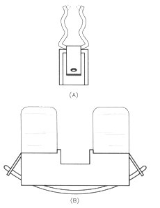
Figure 8 - Making the tap connection to the coll. At A, the ends of the jaws of a 5 mm cartridge fuse holder are bent inward (dotted lines) to grip the heavy wire of the coil. A side view of the fuse holder is shown at B. Bend the solder lugs at the ends of the f use holder to accept a wire passing through them and beneath the f use-holder base. When this wire is in place, bend the lugs farther up against the ends of the holder end solder them. Strip a 1/4 inch of insulation from the tap wire end solder it to the wire joining the lugs beneath the fuse holder. Round off any sharp points or rough edges with a file, because you'il be gripping this connector tightiy for attachment to end rernoval from the coil.
Antenna operation with the coil
To use the antenna on 40 through 10 meters, shorten the mast to 6 feet 2 inches and connect the coil to the mast. Atop the coil, add an element consisting of two horizontal 3.5 foot lengths of 1/8 inch diameter tubing, or a single 7 foot vertical piece of tubing. With the full 13 turns of the coil, and part of an extra turn supplied by the tap wire, the antenna will likely resonate in the middle of the 40 meter band. To operate at the low end of the band, add a 1 foot length of tubing to one side of the flattop or the vertical tubing section. See Figure 9 for approximate dimensions of the assembled antenna.
It may seem as though Table 2 has some errors because it lists a greater number of coil turns for operation on 15, 12 and 10 meters than for 17 meters! You're right something strange is going on. lt's because there are two resonant frequencies for each setting of the coil tap. Figure 10 shows the two paths that RF can take in the antenna. The upper part of the coil and the top hat provide the lower frequencies; the lower half of the coil provides the higher frequencies. A coil this large has considerable capacitance to free space, so it's not just an end loading inductor at the higher frequencies. The antenna bandwidth is good, the SWR low and the antenna performs well on these bands. The charm of this coil system is that you can change bands by just moving the tap on the coil, without any adjustments to the mast length or the flattop. And a bonus: With 13 turns on the coil, the antenna works on 40 and 10 meters simultaneously.
The coil settings of table 2 may need some minor adjustments if a vertical top section is used instead of the flattop. In general, the SWR is lower with the flattop and the antenna is easier to handle.
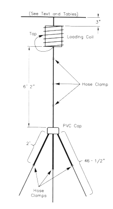
Figure 9 - Approximate dimensions of the assembled antenne with the tripod, most, loading coil end top hat.
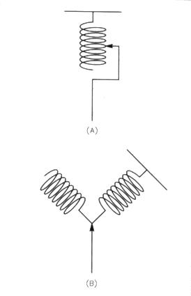
Figure 10 - At A, the upper part of the antenna includes the coll, the adjustable tap and the top hat. The bottom of the coil is free and not connected to anything else. At B, this has been redrawn to show the two antenna circuits with the two resonant frequencies that are present. The upper half of the coil has a lower resonant frequency because of the length of the top het above it.
Table 2
This is table identifies the number of coil turns (counted trom the top of the coil) required to resonate the antenna on the 40 through 10 meter bands. These coiltap settings are provided as a starting point only because installation conditions vary. To raise the antenna's operating frequency, reduce the number of turns used; to lower the operating frequency, increase the number of turns.
| Band (m) | Number of Coil Turns |
|---|---|
| 40 | 13 |
| 30 | 7.1 |
| 20 | 3.1 |
| 17 | 2 |
| 15 | 5 |
| 12 | 7 |
| 10 | 13 |
Power handling capability and safety
Because of the large coil and tubing used, you might be tempted to run high power with this antenna. I suggest you don't. The antenna may take it, but people can't. At high-power levels, dangerous RF voltages on the antenna are within range of physical contact. I have used the antenna at a 100W level, but even that requires care and supervision.
Other possibilities
With the tapped coil, this antenna can be tuned to any frequency from 7 to 40 MHz when operated on the ground coupled tripod, and up to 110 MHz with the tripod insulated from ground.
The antenna also may be used with a longer mast for greater efficiency, or with a shorter mast when space is restricted. Even though the short version is only about 6 feet high, you can't use it indoors because it must be coupled to earth ground. The taller antenna gets out better, but band changing is more complicated. If operation on 75 and/or 80 meters is a must, you can add another coil to the antenna just below the 40 meter coil and change antenna frequencies with the 40-meter tap. Adding a coil made of 20 close-wound turns of #12 enameled wire wound on a 4-inch styrene form similar to the one in Figure 7 will allow you to tune the antenna from about 3.5 to 3.8 MHz, and from about 3.8 to 4.1 MHz with the top hat reduced to one 3.5 foot section and one 2 foot section. Six groundcoupling strips will provide a lower SWR on 80. A small vertical like this is not very effective for short skip ragchewing, however. A 1/4 λ wire draped over bushes, flower beds or low tree branches offers more high-angle radiation.
Notes
- 'Rick Lindquist, WRL, and Steve Ford, WB81MY, "Compact and Portable Antennas Roundup", 'Alpha Delta Outreach/Outpost System, Product Review', QST, Mar 1998, pp 72-73.
- Twelve feet of each tubing size is needed. The aluminum tubing is available from Texas Towers and Metal and Cable Corp. See their ads elsewhere in this issue.
- The thin walled 1/8-inch-diameter aluminum tubing is available from Home Depot and hardware stores as aluminum clothes poles, each about seven feet long.
- Adhesive-backed aluminum tape 2.5 inches wide is available f rom Home Depot stores in the heating-vent section.
- You may want to consider using an antioxidant at the tubing joints. Antioxidant compounds availabie from electrical wholesale supply houses, Home Depot and hardware stores include Noalox (Ideal Industries Inc, Becker PI, Sycamore, IL 60178; tel 800-435-0705, 815-895-5181, fax 800-533-4483) and OX-GARD (GB Electrical, 6101 N Baker Rd, Milwaukee, WI 53209; tel 800-558-431 l). Use either sparingly; a thin coat is suff icient.-Ed.
- Aluminum angle 1.5 × 1.5 × 1/16 inch thick is available from hardware and Home Depot stores. The green plastic ground stake that threads into the ground hes the name "Twizelpeg" stamped into it, and is available at camping supply stores.
- The #8 aluminum wire is RadioShack #15-035.
- The coupling is available from Home Depot in the drainage pipe section, and also from large plumbing or swimming pool distributors. The couplings are actually 4.5 inches in diameter and made from polystyrene, a very low-loss insulator.
- RadioShack #270-738.
W3JIP, ksjohns@email.msn.com