A simple TRF receiver or tracking RFI
If the notion of a quiet band seems like a dream from the distant past, don't despair! This project can help you track down RFI and restore serenity to your shack.
The hum, buzz and whine we call line noise may come from electrical faults associated with local utility lines, or it may originate from custorner-owned electrical and electronic equipnient that has turned power lines and other wiring into antennas. Regardless of the source, RFI can be difficult to track at HF beeause it tends to travel long distances along wiring and evade localization. At VHF, however, noise-propagation distance is dramatically shorter and pinpointing trouble spots becomes correspondingly easier.
If unwanted noise is spoiling your operating fun, it's quite likely that a quick search with a VHF tracking receiver could easily piek up the offending racket within a few blocks of your home. Frorn there, you may be able to locate a specific utility pole number, building, or equipment site and report it to the responsible party. Of course, local noise sometimes originates a little eloser to home-in your utility room, office, workshop, VCR, dimmer switch or ham shack! No matter where the problem lurks, this receiver will help you sniff out noise and track it to the source.
General Description
The project is a simple tuned-radio-frequency (TRF) receiver operating at about 136 MHz, in the upper portion of the aircraft band. I say "about" because TRF receivers have no local oscillator to establish a specific central operating frequency and no IF selectivity to provide narrow channel separation between individual stations. Instead, a TRF receiver covers afirequency span, which is determined solely by multiple sections of preselective filtering ahead of the detector (a form of direct conversion). If this approach sounds unsophisticated, remember that the real purpose of a noise receiver is to sample everything occurring in a broad range of frequencies rather than select individual signals. In fact, for noise Investigation, the TRF is a better tool than its more complex counterpart, the superhet.
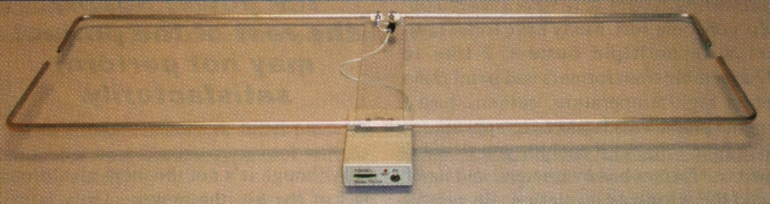
The package consists of a handheld receiverlantenna combination: You simply point the antenna in the direction of suspected noise sources. A Moxon rectangle antenna attached to the receiver case delivers directivity. This miniature Yagi, originally deseribed by Les Moxon and profiled extensively by L.B. Cebik, has a well-defined cardioid pattern.(1) The broad front lobe is useful for identifying the general direction of a noise source, and the pronounced backfield null can provide directivity rivaling that of a 5- or 6-element Yagi when you get in close. To use the null, simply turn the unit around in your hand and rotate it for minimum rather than maximum signal. To preserve the symmetry of the cardioid pattern, a current choke decouples the outer surface of the coax feed line from the antenna feedpoint.
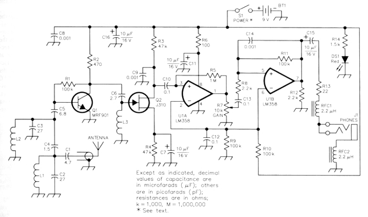
Figure 1-Schematic of the TRF RFI receiver. Unless otherwise specified, resistors are 1/4-W, 5%-tolerance carbon composition or metal-film units. Equivalent parts can be substituted; n.c. indicates no connection.
| BT1 9 V battery C1 - 4.7 pF disc ceramic C2, C3 - 27 pF multilayer C4 - 1.5 pF disc ceramic; a 2-pF capacitor may be used if a 1.5-pF unit is unavailable. C5-6.8 pF disc ceramic C6-2.7 pF disc ceramic C7, C11, C15, C16 - 10 µF, 16 V electrolytic. C8, C9, C14 - 1 nF Cl0, Cl2, Cl3 - 1 µF |
DS1 - Red T1 3-mm LED J1 - 3.5 mm three-circuit (stereo) mini jack. L1, L2 - Air-wound inductor made of 5 turns #24 tinned wire formed on the threads of a #6-32 screw. L3 - Air-wound inductor made of 11 turns #24 tinned wire formed on the threads of a #8-32 screw. Ql - MRF-901 Q2 - J310 N-channel FET |
R1, R9, R11 - 100 kΩ R2 - 470 Ω R3, R4 - 47 kΩ R6 - 100 Ω R7 - 10 kΩ PC-mount pot with switch. R8, R12 - 2.2 kΩ R13 - 22 Ω R14 - 1.5 kΩ RFC1, RFC2 - 2.2 mH molded choke S1- SPST toggle (part of R7). U1-LM358 dual op amp |
Circuit Description
The receiver schematie is shown in Figure 1. The selective elements that define the receiver's operating span include its resonant antenna, a two-pole Butterworth filter (L1, L2, C1 and C5) on the input side of RF preamp Q1 and a high-Q tuned-in-put circuit (L3) at the gate of the AM pulse detector Q2. Together, these selective circuits establish a -10 dB bandwidth of approximately 2 MHz and provide relatively deep passband skirts to keep out unwanted interference from strong TV and FM broadeast stations.
Q1 is a low-noise UHF bipolar device that delivers a gain of roughly 20 dB. Q2 is a high-transconductance FET configured as an infinite-impedance AM detector. Detected audio is recovered at the drain of Q2 and amplified to headphone level by dual op amp U1. The first audio stage, U1A, is set for near-maximum gain by feedback resistor R5. Output from this stage is coupled to U1B through attenuator R7, the GAIN control. U1B is set for a gain level consistent with stable operation by R11, with HF roll off provided by C14. U1B develops sufficient output to drive a pair of Walkman-type stereo headphones at modest volume. RFC1 and RFC2 isolate J1 from the receiver PC board, preventing headphone leads from acting as an antenna and interfering with the Moxon Rectangle. The unit's power switch is part of the attenuator pol: R7, and an LED (DS1) serves as both a pilot light and battery condition indicator. Circuit current drain is approximately 12 mA, permitting several hours of operation from a single 9V battery. The notion of using a TRF design at VHF for noise detection was inspired by a simple UHF AM wideband-data receiver circuit described in RF Design Magazine.(2) However, for this particular application, I used commonly available experirnenter parts and added an RF preamp to increase sensitivity. I also routed the output of Q2 to the lower-impedance inverting input of U1A to provide heavier detector loading. This change reduces a tendency toward AF instability, yielding a 10 dBm improvernent in overall receiver performance.
Given its simplicity, the receiver is quite sensitive. On the bench, the detection threshold for a weak narrowband AM signal at the passband center measured -100 dBm. This level of receiver sensitivity, combined with the antenna's gain, enhances weak-signal reception. The receiver has no signal-strength metering system, nor does it need one. Relative signal strength is measured audibly-by listening to differences in loudness in the headphones. Gain is controllable over a wide signal range by the manual attenuator, R7, so even small amplitude changes are easy to detect. The lack of AGC in a receiver of this type could prove problematic, except that U1B has limited output capability. If an extremely strong signal suddenly appears at a high gain setting, U1B saturates at a sufficiently low level to protect your eardrums.
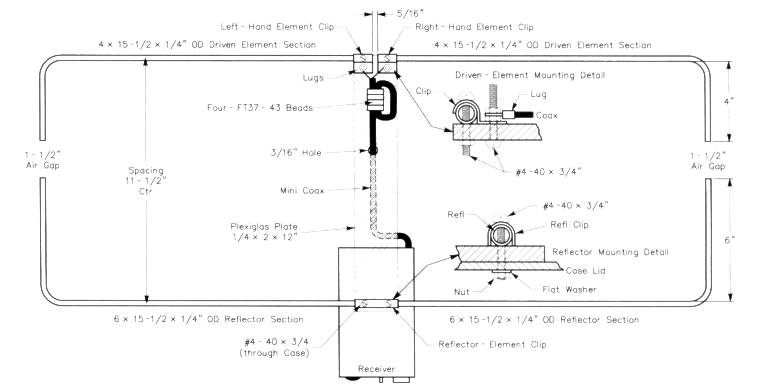
Figure 2 - Antenna assembly details. See table 1 for a list of parts needed. The driven- and reflector-element clamps are made of 0.032 inch hobby aluminum stock.
Antenna Construction
Figure 2 shows the Moxon rectangle antenna is constructed from four lengths of 1/4 inch OD aluminum tubing. The short sections of the driven and reflector elements are four and six inches long, respectively. The most difficult task is shaping the 90° element bends without crimping and breaking the tubing. Gently heating the tubing prior to bending will help. Use a small tubing bender, or use the partially, open jaws of a vise as a fulerum to form the bend progressively in four or five increments. Complete each bend and check it with a square before cutting the element section to length. Once formed, clamp the element sections to a 1/4x2x12-inch plexiglas or plastic mounting plate.
Form the element-retainer clips from 0.032-inch aluminum hobby stock. To radius the clips, shape them over the shank of a 7/32 inch drill bit, then with the help of a vise, trim and bend each one to shape. The radius should be slightly undersized to exert clamping pressure on the 1/4 inch OD element. To prepare for mounting, drill alining holes (#4-40 clearance) through each clip, element section and the anterma- mounting plate, as shown. Prepare short pigtails on the antenna end of the coaxial feed line and install spade lugs for attachment to the driven-element hardware. Loop the feed line through four FT37-43 beads to form the feed-line choke. Finally, pass the feed line through its guide hole to the underside of the plate entry into the receiverbox. The antenna plate mounts on top of the receiver case using the two reflectorelement mounting screws. Use #6 flat washers or better yet, a small aluminum plate inside the plastic case to increase retention area and add strength to the antenna mount.
After mounting the elements, adjust the element tips for an air-gap of approximately 1.5 inch. Although some authors suggest installing insulators between the element tips to add rigidity, I don't recommend it. Range tests carried out at 150 MHz using a variety of nonconductive materials resulted in resonance shifts and degraded back-null performance. NEC plots representing the antenna pattern assume air gaps and fail to show this effect. If you have access to a VHF antenna analyzer, test your antenna before mounting it on thie receiver case; the SWR should be 1.2:1 or better at resonance. According to an HP8735E, my test antenna indicated a virtually flat response at 136.6 MHz. If the antenna resonance falls a little below or above the 136-MHz target frequency, there's no need to readjust the antenna. Simply note where minimum SWR occurs and peak your receiver for that particular frequency.
Antenna Parts List
2 Reflector-element sections 1/4 inch OD 15.5 x 6 inch aluminum tubing; see text and Figure 2.
2 Driven-element sections 1/4 inch OD 15.5 x 4 inch aluminum tubing; see text and Figure 2.
1 Right-hand driven-element mounting clip; see text.
1 Left-hand driven-element clip; see text.
6 #4-40 x 3/4-inch screws
8 #4-40 nuts with integral lock washers, or use separate items.
2 #4-40 flat washers 2 #6 spade lugs
1 18-inch length of miniature 50 Ω coax (RG-174)
4 FT37-43 ferrite cores
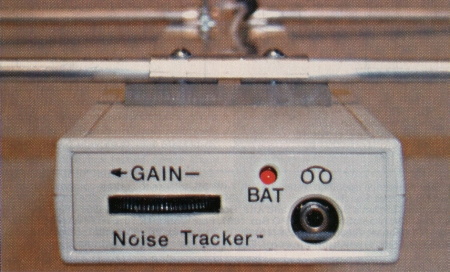
A close-up view of the receiver's front panel.
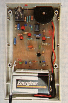
An inside view of the neatly assembled TRF RFI receiver prototype. |
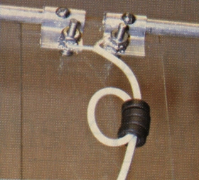
Loop the feed through four FT37-43 beads to form the feed-line choke to decouple the outer surface of the feed line from the antenna feedpoint. |
Receiver construction
The receiver is built on a single-sided PC board wth a generous ground plane and construction is straightforward .(3) Because this is, a VHF project, be sure to keep all capacitor leads in the RF section as short as possible. L1, L2 and L3 are air-wound coils. Wind L1 and L2 on a #6-32 screw; form L3 using a #8-32 screw. When installing the MRF-901 preamp, note that the collector is the longest of the four leads. To mount pot R7, first remove its thumbwheel, then lay the control lugs flat on the top of the PC board. Secure each lug in place at its mounting hole using a short piece of wire (a discarded component-lead end will do). When mounting DS1, leave the leads nearly full length so the LED lens can protrude through its mounting hole near the top of the front panel (the shorter LED lead goes to the foil-side mounting hole).
For the receiver case, I used a Pan-Tec 1 x 2.3 /4 x 4.1/8 inch (HWD) project box (RadioShack 910-5006). To prepare the case, begin by clamping both halves together and drilling a 1/8-inch hole in the rear panel to pass the feed line. Center this hole on the case split and not more than 3/16 inch from the right-hand corner. The feed line, passing through this hole, is clamped in place when the box is assembled. Next, drill two #4-40 clearance holes in the top of the case approximately 1.7/8 inch forward of the back panel. These holes are used to mount the antenna assembly (use the antenna plate as a drilling template). Finally, prepare the removable front panel.(4) To cut the thumbwheel slot for R7, drill a line of small holes to rough out the opening, then carefully finish the hole with an X-acto knife and a small file. Panel lettering may be added using dry transfers, or using your PC and a program (such as MS Draw) to make a full-sized panel decal.
Receiver testing and tune-up
Testing and alignment is done with the receiver PC board out of the case. Install a fresh battery, plug in a pair of stereo headphones and turn the GAIN control to maximum. You should hear a background hiss that increases in both volume and high-frequency response with higher gain settings. Alignment consists of tuning Ll through L3 for maximum sensitivity at the antenna's resonant frequency. If you have access to a modest calibrated signal generator (HP-8640B, Wave-Tek 3000, etc), tune-up will be a snap. Connect the receiver to the generator by a short length of temporary feed line. Set the generator for the desired frequency with 1 kHz AM modulation adjusted to 80-90% and output set at approximately -60 dBm (reduce the generator output as needed while tuning). Tune L1 through L3 by gently stretching or compressing windings using the tip of a plastic insulated tool. For a more precise tuning indication, attach a 'scope or sensitive ac voltmeter to R13. Repeat the tuning sequence until there's no further improvement. With L1-L3 fully peaked, a -90-dBm signal should be comfortably audible and you may detect audio down to -100 dBm or beyond.
If you don't have access to a calibrated generator, use a VHF antenna analyzer to produce a test signal. Don't connect the antenna analyzer directly to the receiver, you may damage the preamp and detector. Instead, terminate the receiver's antenna terminals temporarily with a 47 Ω resistor. Tune the analyzer to the antenna's resonant frequency and position it a suitable distance away to yield a noisy but usable signal level. Most analyzers have audible AM superimposed on the signal by internal processor or counter transients. Don't attempt to optimize the receiver.for maximum background noise without using a generator or calibrated signal source. The TRF design must be peaked for maximum sensitivity (it the resonant.frequency of the Moxon antenna in order to take advantage ofthe antenna's characteristic cardioid pattern.
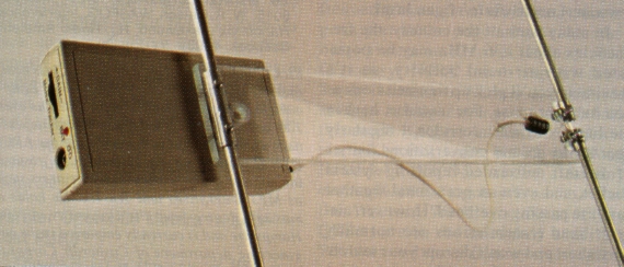
A topside view of the tracking receiver and antenna. The receiver is atteched to the antenna and plexiglas strips by two screws.
Final assembly
Once tuned, avoid moving L1-L3 while connecting the miniature feed line and installing the PC board in its case. To assemble the case, slip its end panel over the GAIN control and make sure the LED, DS1 protrudes through its opening.Guide the end panel and PC board into the bottom half of the case and route miniature coax over its exit groove. Route the battery clip out through the open battery compartment door. Attach the antenna assembly to the top half of the case by means of the antenna's reflector-mounting screws and secure it in place. Finally, sandwich the case together and install the assembly screws.
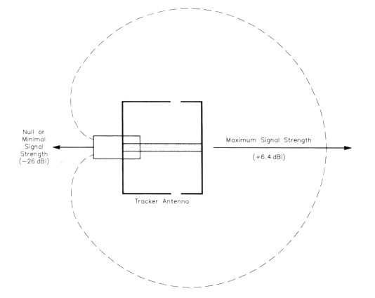
Figure 3 - A Moxon rectangle antenna pattern. Note that the pattern null points toward the user.
Operation
To operate your receiver, simply turn it on and direct the antenna toward suspected noise sources. As a rule, the Moxon's broad forward lobe is best for identifying general locations and the sharper back null is best for pinpointing specific nearby sources (Figure 3). A word of caution: In the real world, multipath, polarity differences and many other anomalies may appear to muddy the antenna's ideal cardioid response pattern. Fortunately, you can shift polarity with a twist of the wrist, and shift location in terms of antenna wavelengths by moving only a few feet.
RFI comes from many sources, including ac power-line sparking, electric-fence arcing, motors and control circuitry, noisy lighting equipment, defective switching supplies, leaking computer networks and much more. Also, 136 MHz coincides with cable channel 16, so a strong buzzing sound may be the result of sync-pulse noise from TV-cable leakage rather than ac-line noise (the two sounds can be very difficult to distinguish). A quick check with an AM broadcast radio will usually resolve this question, since TV sync won't appear in the AM band while a strong ac line noise will.
There are many tricks and techniques for isolating RFI sources and for identifying the exact type of fault they represent-far too many to cover here. For the amateur noise hunter, two excellent resources are available. I strongly recommend The ARRL RFI Book prepared by ARRL Lab Supervisor, Ed Hare, W1RFI, his choice of call being no coincidence.(5) I also suggest obtaining the Interference Handbook by William R. Nelson, WA6FQG, which is also available from the ARRL and most ham-radio bookstores.(6) Both books are packed with useful information. Finally, see the ARRL's Technical Information Services RFI pages.
In many parts of the country, the frequencies about 136 MHz may be populated with air-band activity, so it's inevitable you'll pick up transmissions as you hunt for noise. For instance, here in the busy Northeast corridor, I regularly hear air-to-ground conversations, bursts of aircraft automated-reporting-system packet, and even an occasional weather satellite passing overhead. However, aircraft-band transmissions are normally very short and won't disrupt your search. Moreover, intermittent chatter provides reassurance that the receiver is working properly.
Summary
RFI levels are increasing in most communities. The same interference that plagues Amateur Radio affects other services as well. For example, many municipal police and fire departments struggle with decreased handheld portable coverage because of rising noise floors. Also, regional FM broadcasters now routinely install low-power translators to overcome degraded reception in noisy downtown areas. Excessive RFI is not just a ham problem; it's a community problem affecting everyone with an interest in communicating by radio!
FCC policy dictates that our licensed radio services need not tolerate excessive RFI levels. However, Federal enforcement is stretched to the firnit and local electrical inspectors usually lack the equipment and training to intervene. Thus, neighborhood, RFI detection and reporting often falls to utility companies and radio amateurs like you and me. If you're tired of local noise invading our bands, why not join the cleanup and perform a public service at the same time? This simple hand-held project-plus a little legwork-may be all it takes to restore a cleaner spectrum, for you and your neighbors!
Notes
- L. B. Cebik, W4RNL, "Modeling and Understanding Small Beams, Part 2, VK2ABO Squares and Moxon Rectangles", Communications Quarterly, Spring 1995, pp 55-70.
- Robert Friday and John Neder, "A Low-Cost UHF AM Receiver", RF Design, Nov 1991, pp 31-36.
- A parts kit including the PC board (but excluding case and antenna) is available from Rick Littlefield, K1 BOT, PO Box 465, Barrington, NH 03825. Price: $29.95 plus $4 shipping and handling.
- A front-panel template/labeling guide and a PC-board part-placement pictorial are available f rorn the ARRL ftp site at www.arrl.org/files/qst-binaries/ in TRFRFI.ZIP.
- See www.arrl.org/shop/, order number 6834. Ed Hare, W1 RFI, The ARRL RFI Book (Newington: ARRL, 1999, 1 st ed).
- See www.arrl.org/shop/, order number 6015. W. R. Nelson, WA6FQG, Interference Handbook (Lakewood, NJ: Radio Amateur Callbook, 1993).
K1BQT: k1bqt@aol.com