An automatic sealed-lead-acid battery charger
This nifty charger is just what you need to keep your SLA batteries up to snuff!
After experiencing premature failure of the battery in my Elecraft PALK2 transceiver (most likely because I forgot to keep the battery on a regular charge schedule), I began searching for an automatic battery charger.(1)(2) The K2 uses a Power-Sonic PS-1229A 12-V, 2.9-Ah sealed lead-acid (SLA) battery. SLAs are commonly called gel-cells because of their gelled electrolyte. As with all things, to obtain maximum service life from an SLA battery, it needs to be treated with a certain degree of care. SLA batteries must be recharged on a regular basis; they should not be undercharged or overcharged. If an SLA battery is left unused, it will gradually self-discharge.
Although my SLA battery experiences related here are linked to my K2 transceiver, you can think of the K2 simply as a load for the battery. The comments pertaining to the SLA batteries and chargers apply across the board and the charger described here can be used with any similar battery.
Using a three-mode charger
My first attempt at keeping my K2's SLA battery healthy was to purchase an automatic three-mode charger. I soon discovered that most three-mode chargers work by sensing current and were never intended to charge a battery under load. Three-mode chargers begin the battery charging process by applying a voltage to the battery through a 500-mA current limiter. This stage is known as bulk-mode charging. As the battery charges, its voltage begins to climb. When the battery voltage reaches 14.6 V, the charger maintains the voltage at that level and monitors the battery charging current. This is known as the absorption mode, sometimes called the overcharge mode. By this time, the battery has achieved 85% to 95% of its full charge. As the battery continues to charge-with the voltage held constant at 14.6 V-the charging current begins to drop. When the charging current falls to 30 mA, the three-mode charger switches to float mode and lowers the applied voltage to 13.8 V. At 13.8 V, the battery becomes self-limiting, drawing only enough current to offset its normal self-discharge rate. This works great-until you attach a light load to the battery, such as turning on the K2 receiver. The K2 receiver normally draws about 220 mA. When the charger detects a load current above 30 mA, it's fooled into thinking that the battery needs charging, so it reverts to the absorption mode, applying 14.6 V to the battery. If left in this condition, the battery is overcharged, shortening its service life.
UC3906-IC chargers
Chargers using the UC3906 SLA charge-controller IC work just like the three-mode charger described earlier except that their return from float mode to absorption mode is based on voltage rather than current. Typically, once the charger is in float mode it won't return to absorption mode until the battery voltage drops to 10% of the float-mode voltage (or about 12.4 V). Although this is an improvement over the three-mode charger, it still has the potential for overcharging a battery to which a light load is attached.
First, let's look at the situation where a UC3906-controlled charger is in absorption mode and you turn on the K2 receiver, applying a load. The battery is fully charged, but because the load is drawing 220 mA, the charging current never drops to 30 mA and the charger remains in absorption mode, thinking that it is the battery that is asking for the current. As with the three-mode charger, the battery is subject to being overcharged.
If we remove the load by turning off the K2, the current demand drops below 30 mA and the charger switches to float mode (13.8 V). When the K2 is turned on again, because the charger is able to supply the 220 mA for the receiver, the battery voltage doesn't drop, so the charger stays in float mode and all is well. However, if the transmitter is keyed (increasing the current demand), the charger can't supply the required current, so it's taken from the battery and the battery voltage begins to drop. If we unkey the transmitter before the battery voltage reaches 12.4 V, the charger stays in float mode. Now it takes much longer for the charger to supply the battery with the power used during transmit than it would have if the charger had switched to absorption mode.
SLA batteries must be recharged on a regular basis.
Let's key the transmitter again, but this time keep it keyed until the battery voltage drops below 12.4 V. At this point, the charger switches to the absorption mode. When we unkey the transmitter, we're back to the situation where the charger is locked in absorption mode until we turn off the receiver.
Why worry?
So, why this concern about overcharging an SLA battery? At 13.8 V, the battery self-limits, drawing only enough current to offset its self-discharge rate (typically about 0.001 times the battery capacity, or 2.9 mA for a 2.9 Ali battery). An SLA battery can be left in this floatcharge condition indefinitely without overcharging it. At 14.6 V, the battery takes more current than it needs to offset the self-discharge. Under this condition, oxygen and hydrogen are generated faster than they can be recombined, so pressure inside the battery increases. Plastic-cased SLA batteries such as the PS-1229A have a one-way vent that opens at a couple of pounds per square inch pressure (PSI) and release the gases into the atmosphere. This results in drying the gelled electrolyte and shortening the battery's service life. Both undercharging and overcharging need to be avoided if we want to get maximum service life from the battery. Continuing to apply 14.6 V to a 12V SLA battery represents a relatively minor amount of overcharge and results in a gradual deterioration of the battery. Applying a potential of 16 V or excessive bulk-charging current to a small SLA battery from an uncontrolled solar panel can result in serious overcharging. Under these conditions, the overcharging can cause the battery to overheat, which causes it to draw more current and result in thermal runaway, a condition that can warp electrodes and render a battery useless in a few hours. To prevent thermal runaway, the maximum current and the maximum voltage need to be limited to the battery manufacturer's specifications.
Design decision
To avoid the potential of overcharging a battery with an automatic charger locked up by the load, I decided to design my own charger, one that senses battery voltage rather than gurrent in order to select the proper charging rate. A 500-mA current limiter sets the maximum bulk rate charge to protect the battery and the charger's internal power supply. Like the three-mode chargers, when a battery with a low terminal voltage is first connected to the charger, a constant current of 500 mA flows to the battery. As the battery charges, its voltage begins to climb. When the battery voltage reaches 14.5 V, the charger switches off. With no charge current flowing to the battery, its voltage now begins to drop. When the current has been off for four seconds, the charger reads the battery voltage. If the potential is 13.8 V or less, the charger switches back on. If the voltage is still above 13.8 V, the charger waits until it drops to 13.8 V before turning on. The result is a series of 500-mA current pulses varying in width and duty cycle to provide an average current just high enough to maintain the battery in a fully charged condition. Because the repetition rate is very low (a maximum of one current pulse every four seconds) no RFI is generated that could be picked up by the K2 receiver. Because the K2's critical circuits are all well regulated, slowly cycling the battery voltage between 13.8 V and 14.5 V has no ill effects on the transmitted or received signals.Thermal runaway can warp electrodes and render a battery useless in a few hours.
As the battery continues to charge, the pulses get narrower and the time between pulses increases (a lower duty cycle). Now when the K2 receiver is turned on and begins drawing 220 mA from the battery, the battery voltage drops more quickly so the pulses widen (the duty cycle increases) to supply a higher average current to the battery and make up for that taken by the receiver. When the K2 transmitter is keyed, it draws about 2 to 3 A from the battery. Because the charger is current limited to 500 mA, it is not able to keep up with the transmitter demands. The battery voltage drops and the charger supplies a constant 500 mA. The battery voltage continues to drop as it supplies the required transmit current. When the transmitter is unkeyed, the battery voltage again begins to rise as the charger replenishes the energy used during transmit. After a short time, (depending on how long the transmitter was keyed) the battery voltage reaches 14.5 V and the pulsing begins again. The charger is now fully automatic maintaining the battery in a charged condition and adjusting to varying load conditions.
The great thing about this charging system is that during transmit the majority of the required 2 to 3 A is taken from the battery. When you switch back to receive, the charger is able to supply the 220 mA needed to run the receiver and deliver up to 280 mA to the battery to replenish what was used during transmit. This means that the power source need only supply the average energy used over time, rather than being required to supply the peak energy needed by the transmitter. (You don't need to carry a heavy 3-A regulated power supply with your K2.) As long as you don't transmit more than about 9% of the time, this system should be able to power a K2 indefinitely.
Have you ever noticed that sometimes when your H-T has a low battery and you drop it into its charger you hear hum on the received signals? This charger's power supply is well filtered to ensure that there is no ripple or ac hum to get into the K2 under low battery voltage conditions.
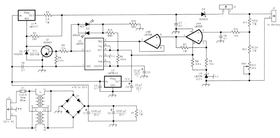
Figure 1
| C1, C2 - 2200 µF, 35 V electrolytic C3, C6, C7, C8 - 0.1 µF, 50V metallized C4, C5 22 µF, 25 V tantalum D1 - 400 V, 4 A bridge rectifier D2 - 1N5245, Zener diode, 15 V, 500 mW D3 - Bicolor LED, red/green D4 - 1N5820 Schottky diode F1 - 250 mA slow-blow fuse J1 - 2-pin header, PC mount J2 - 2-pin connector, PC mount J3 - 3-pin connector, PC mount Q1 - 2N4401 NPN transistor R1 - 1 kΩ 1 W, 5% R2 - 240 Ω R3 - 2.4 Ω 1 W, 5% R4 - 2.2 kΩ R5 - 12 kΩ R6 - 150 Ω |
R7 - 1 MΩ R8 - 3.6 kΩ R9, R10 10 kΩ R11 - 100 Ω 1/4 W, 1 % R12-16.2 k" 1/4 W, 1% R13 - 20 kΩ, multiturn pot R14, R15 - 680 Ω T1 -15 V/666 mA UI - LM137 - T voltage regulator, TO-220 case U2 - LM555 - timer U3 - LM78L12 voltage regulator, TO-92 case U4 - LM358 - dual opamp U5 - LM336, 2.5 V voltage reference, TO-92 case Misc: PC-boeard(3); TO-220 heat sink; five 1/4 inch #4-40 stand-offs; two fuseholder clips, PC mount; two-pin shunt; two-pin connector housing; three pin connector housing four housing pins; enclosure |
Circuit description
The charger schematic is shown in Figure 1. I've dubbed the charger the PCR12-500A, short for Pulsed-Charge Regulator for 12-V SLA batteries with maximum bulk charge rates of 500 mA. U1, an LM317 three-terminal voltage regulator, is used as a current limiter, voltage regulator and charge-control switch. A 15-V Zener diode (D2) sets Ul to deliver a no-load output of 16.2 V. R3 sets U1 to limit the charging current to 500 µA. When Q1 is turned on by the LM555 timer (U2), the ADJ pin of U1 is pulled to ground, lowering its output voltage to 1.2 V. D4 effectively disconnects the battery by preventing battery current from flowing back into U1. A Schottky diode is used at D4 because of its low voltage drop (0.4 V).
An LM358 (U4A) operates as a voltage comparator. U5, an LM336, provides a 2.5-V reference to the positive input (pin 3) of U4. R11, R12 and R13 function as a voltage divider to supply a portion of the battery voltage to pin 2 of U4A. R13 is adjusted so that when the battery terminal voltage reaches 14.5 V, the negative input of U4A rises slightly above the 2.5-V reference and its output switches from +12 V to 0 V. When this happens, the I-MC2 resistor (R7) causes the reference voltage to drop a little and provide some hysteresis. The battery voltage must now drop to approximately13.8 V before U4A turns back on.
U4B is a voltage follower. It pulls the trigger input (pin 2) of U2 -to 0 V, causing its output to go to 12 V. U4B's output remains at 12 V until C5 has charged through R6 (approximately four seconds) and the trigger has been released by U4A sensing the battery dropping to 13.8 V or less. While the output of U2 is at 12 V, emitter/base current for Q I flows via R5 and Q I's collector pulls U I's ADJ pin to ground, turning off the charging current.
The output of U2 also provides either + 12 V or 0 V to the bicolor LED, D3. R14 and R15 form a voltage divider to provide a reference voltage to D3 such that D3 glows red when U2's output is + 12 V and green when U2's output is at 0 V. When ac power is applied but U1 is switched off and not supplying current to the battery, D3 glows red. When U I is on and supplying current to the battery, D3 is green. As the battery reaches full charge, D3 blinks green at about a four-second rate. As the battery charge increases, the on time of the green LED decreases and the off time increases. A fully charged battery may show green pulses as short as a half-second and the time between pulses may be 60 seconds or more.
T1, D1, C1 and C2 form a standard full-wave-bridge power supply providing an unregulated 20 V dc at 500 mA. U3, an LM78LI2 three-terminal regulator, provides a regulated 12-V source for the control circuits.
Note that the mounting tab on U1 is not at ground potential. U1 should be mounted to a heat sink with suitable electrically insulated but thermally conductive mounting hardware to avoid short circuits. Suitable mounting hardware is included with the PC board(4).
Other bulk-charge rates
The maximum bulk-charge rate is set by the value of R3 in the series regulator circuit. The formula used to determine the value of this resistor is Rohms = 1200 / ImA, T1 must be capable of supplying the bulk charge current and U1 must be rated to handle this current. The LM317T used here is rated for a maximum current of 1.5 A provided it has a heat sink sufficiently large enough to dissipate the generated heat. If you increase the bulk-charge rate, you'll definitely need to increase the size of the on-board heat sink. Mounting U1 directly to the housing (be sure to use an insulator) may be a good option.
Transformer substitution
I selected T1 because of its small size and PC-board mounting. You can substitute any transformer rated at 15 or 16 V ac (RMS) at 500 mA or more. You may find common frame transformers to be more readily available. You can mount such a transformer to an enclosure wall and route the transformer leads to the appropriate PC-board holes.Construction
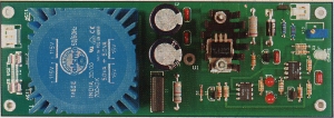
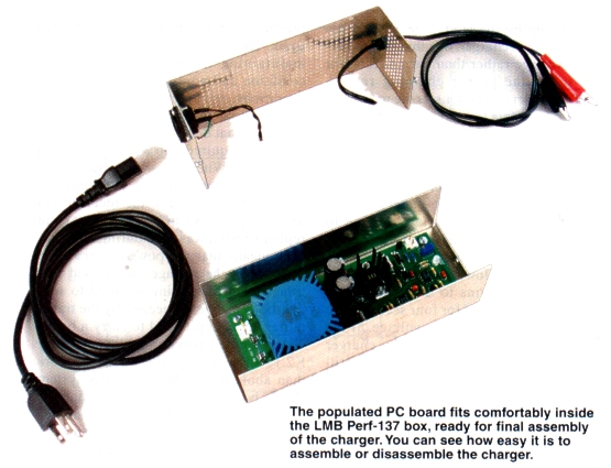
There is nothing critical about building this charger. You can assemble it on a prototyping board, but a PC board and heat sink are available.(4) The specially ordered heat sink supplied with the PC board is 1/4-inch higher than the one identified in the parts list and results in slightly cooler operation of U1.
Be sure to space R1 and R3 away from the board by 1/4 inch or so to provide proper cooling. R13 can be a single-turn or a multiturn pot. You'll probably find a multiturn pot makes it easier to set the cutoff voltage to exactly 14.5 V
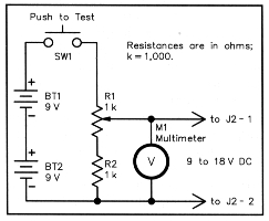
Figure 2 - Test voltage source for the battery charger
R13 adjustment
To check for proper operation and to set the trip point to 14.5 V dc, we need a test-voltage source variable from 12 to 1-5 V dc. A convenient means of obtaining this test voltage is to connect two 9 V transistor-radio batteries in series to supply 18 V as shown in Figure 2. Connect a 1 W resistor (R2) in series with a 1 kΩ potentiometer (R 1) and connect this series load across the series batteries with the fixed-value resistor to the negative lead. The voltage at the pot arm should now be adjustable from 9 to 18 V. During the following procedure, be sure to adjust the voltage with the test supply connected to the charger at J2 because the charger loads the test-voltage supply and causes the voltage to drop a little when it's connected.
Remove the jumper at J I and apply ac line voltage to the unit at B. Turn R13 fully counterclockwise. D3 should glow green. Connect the test voltage to J2 and adjust RI of Figure 2 for an output of 14.5 V. Slowly adjust R 13 clockwise until D3 glows red. To test the circuit, wait at least four seconds, then gradually reduce the test voltage until D3 turns green. At that point, the test voltage should be approximately 13.8 V. Slowly increase the test voltage again until D3 turns red. The test voltage should now read 14.5 V. If it is not exactly 14.5 V, make a minor adjustment to R13 and try again. The aim of this adjustment is to have D3 glow red just as the test voltage reaches 14.5 V.
To test the timer functioning, remove the test voltage from J2 and set it for about 15 V. Momentarily apply the test voltage to J2. D3 should turn red for approximately four seconds, then turn green. The regulator is now calibrated and ready for operation. Remove the test voltage and ac power and install the jumper at J 1.
A suitable enclosure
I used an 8x3X2.75-inch LMB Perf-137 box (Digi-Key L171-ND) to house the charger. An alternative enclosure is the Bud CU482A Convertabox, which measures 8x4x2 inches (available from Mouser). If you use the Convertabox, be sure to add some ventilation holes directly above the board-mounted heat sink. The LMB Perf box comes with a ventilated cover. If you are inclined to do some metal work, you could build your own enclosure using aluminum angle stock and sheet and probably reduce the size to perhaps 8x3x2 inches. If you use a PC-board-mounted power transformer, watch out for potential shorts between the transformer pins (especially the 120-V ac-line pins) and the case. If you use a metal enclosure, connect the safety ground (green) wire of the ac-line cord directly to the case.
Operation
It is very important that this charger be connected directly to the SLA battery with no diodes, resistors or other electronics in between the two. The charger works by reading the battery voltage, so any voltage drop across an external series component results in an incorrect reading and improper charging. For example, the Elecraft K2 has internal diodes in the power-input circuit, so it's necessary to add a charging jack to the transceiver that provides a direct connection to the battery. Now I can leave my K2 connected to the charger at all times and be assured that its internal battery is fully charged and ready to go at a moment's notice.
Notes
- Larry Wolfgang, WR1B, "Elecraft K2 HF Transceiver Kit," Product Review, QST, Mar , pp 69-74
- Although this charger was designed specifically for use with the Power-Sonic PS-1229A SLA battery used in the Elecraft K2 transceiver, its design concepts have wide ranging applications for battery operated ORP rigs of all types.
- Although it's labeled a 12-V battery, the terminal voltage is nominally 13.8 V with no load.
- A PC Board (double sided, plated through holes, solder masked and silk screened) and heat sink are available from Intelligent Software Solutions, PO Box 522, Garrisonville, VA 22463-0522. Price: $18 plus $1.50 shipping in the US and Canada.
AA4PB: rlewis@staffnet.com