The AMRAD active LF antenna
You can tune into LF activity with this easy-to-build and erect active antenna. As a bonus, you get MF and HF coverage, too-not to mention world-class performance!
The Amateur Radio Research and Development Corporation (AMRAD) is a nonprofit radio club that specializes in cutting-edge, yet fun, Amateur Radio technology. In a jump back to the future, several of us decided to look into low-frequency radio (LF). Many European countries now have an Amateur Radio allocation at 136 kHz, and AMRAD, hoping for a future FCC amateur allocation there-obtained an FCC Part 5 license to operate experimentally on those challenging low frequencies. Many hams wanted to listen to our transmissions, but lacked a suitable receiving antenna. The antenna described here should do nicely.
Some background
The evolution of our present antenna has a proud lineage. AMRAD member Dick (WA3USG) Goodman's Monster Loop is an excellent antenna and met our initial need.(1) I Another member, Bill Farmer, W3CSW, built a loop antenna in his attic that also performs well.(2) Low-frequency veteran Ken Cornell, W21MB, described several active antennas, including his varactor-tuned active antenna.(3) And engineering whiz Andre Kesteloot, N41CK, presented an even better design. His varactor-tuned active antenna has the tuning stage ahead of the FET follower.(4) N41CK's antenna works very well, but like the Cornell design, it must be tuned to the desired frequency. Because of their simplicity and performance, Ralph Burhans' active-antenna designs became popular with LOWFers (low-frequency experimenters) in the 1980s.(5),(6) Even though they're a few years old, Burhans' articles provide important information about the workings of active antennas. These antennas were a starting point in our quest for an improved LF active antenna.
The US Navy gave the club access to some large LF transmitting antennas that were scheduled for demolition. We conducted a series of tests and concluded that for LF receiving, a well-designed active antenna in a low-noise area can perform as well as much larger antennas.(7)
This project
The active antenna described here can be a powerful tool for the future LF-active ham seeking to work Europe and win the Bobek LF Transatlantic Challenge (once an LF Amateur Radio band is allocated by the FCC, of course).
We set out to build a transatlantic grade LF antenna that any ham could build with simple hand tools. We also wanted our design to improve on Burhans' IMD performance to enable urban hams to receive the LF bands without dealing with spurious signals caused by IMD. We also wante our antenna to work to 30 MHz, if possible, to make the antenna generally more useful. We're pleased to report that this antenna exhibits improved IMD performance and has a useful range of 10 kHz to 30 MHz.
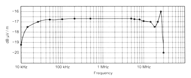
Figure 1 - Active antenna response curve.
What is an active antenna?
An active antenna is an electrically and physically small antenna combined with an active electronic circuit, such as an amplifier. An active antenna, like the one described here, uses a small whip one that is a fraction of a wavelength long at the desired frequency connected to an active impedance-conversion circuit.
An electrically short whip has a high output impedance. For example, a 1 m whip at 10 kHz has an input impedance of almost 2 MΩ. If such a whip were connected directly to a 50 Ω load, signals reaching the antenna would be attenuated almost 114 dB by the time they reached the receiver. The active impedance-conversion portion of this antenna is a high input impedance FET follower feeding a 50 Ω load, eliminating much of the signal attenuation. In this design, the attenuation is only about 16 dB. Reducing the nonlinearity and the resulting IMD products was the major design challenge.
Although the Burhans antennas have IMD performance that exceeds that of many active antennas, urban hams need even better performance. After trying a number of changes to Burhans' designs, we found that performance could be improved by increasing the level at which clipping began and by using a more linear transistor. The problem with increasing the clipping level is that the transistor operating voltage and the bias current almost certainly increase, resulting in increased power dissipation by the transistor.
Simultaneously, we received some key design details from Dr Dallas Lankford, who was working on an HF antenna.(8) He identified the Crystalonics CP-640/CP-650 series of junction FETs as outstandingly linear for active antenna applications. He was kind enough to share his design ideas and provide help with our IMD measurements. AMRAD kudos go to Dallas for his assistance.
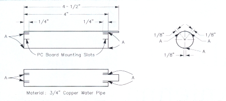
Figure 2 - The heat sink is made from a 4.5 inch piece of 3/4 inch copper pipe cut and shaped as shown. Cut pairs of 1/4 inch deep slots at the "A" points indicated. These form tabs that center the pipe in the PVC tube (see text and figure 5).
The increased transistor heat dissipation is handled by a homemade heat sink constructed from 3 /4 inch copper pipe. Readily available PVC pipe fittings make a protective enclosure for the antenna.
A PC-board prototype was built using a resist pen printed circuit board and, after a few trials and changes, the antenna performed well up to 30 MHz. Three additional antennas were built and used in AMRAD's annual LF expedition to North Carolina's Outer Banks, an environment that has low LF noise and superb LF propagation from Europe (as observed by monitoring European LF broadcast stations). The singular problem is a Coast Guard Loran-C transmitter at Carolina Beach, North Carolina. It operates on 100 kHz, transmitting short, 600-kW pulses.
During the Outer Banks expedition, the new antenna performed well. It was so good that the receiver, a modified Ten-Tec RX-320, became the limiting element.(9) A 136-kHz filter placed between the antenna and the receiver solved the receiver IMD problem and brought receiver sensitivity down to the local noise floor.
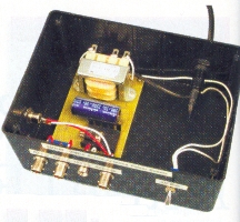
Figure 3 - An interior view of the powersupply enclosure and circuit board.
Power supply
The power supply (see figure 3) is designed to minimize coupling between the power line, the antenna and station ground. The power transformer chosen is the result of carefully testing and sorting commercially available transformers. Similarly, the signals from the antenna are coupled to receiver ports RX1 and RX2 through a wideband isolation transformer, T2. This prevents noise on the receiver ground from coupling into the antenna ground. Isolation ransformers such as this have been invaluable in reducing noise coupling in LF receiving systems.
The power supply has a provision (J4) for using an external 24 V dc source (ie, a battery) for portable operation. 1 or 2 Ah gel-cells provide power for several hours given the 53-mA load. The antenna is designed to work into a 50 Ω load. Ideally, a 50 Ω receiver is attached to RX1 and a high-impedance device, such as an oscilloscope or counter, is connected to RX2. Although the output impedance of RX1 and RX2 is about 14 Q, a load less than 50 Ω degrades the IMD performance. Running multiple receivers on a single antenna has turned out to be very handy at times.
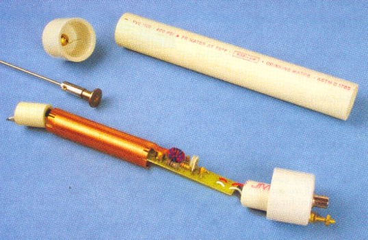
Figure 4-The amplifier, heat sink and PVC tube housing.
Performance
This antenna achieves very good intermodulation and overload performance at some sacrifice in output level. The AMRAD amplifier is based on Burhans' noiseless feedback design. The frequency response curve for the antenna with a 1 m whip is shown in figure 1. The input capacitance of the active amplifier is about 29 pF.
AMRAD member Steve Ratzlaff, AA7U, helped measure the second- and third-order intercept points. Overload and intermodulation performance are measured much as they would be for an RF amplifier or receiver.(10) For second- and third-order intercept point measurements, a hybrid combiner is used." We used a lower-frequency transformer for the hybrid that consisted of 25 bifilar turns of #30 wire on an Amidon FT-87-J ferrite toroid core.
Test signals were fed through a 12-pF capacitor to simulate the source impedance of a 1 meter whip. Referenced to the antenna output, the following values were measured: 1-dB compression point, +25 dBm; second-order intercept point, +53 dBm; third-order intercept point, +37 dBm.
The performance of the AMRAD antenna considerably exceeds that of every readily available active antenna we tested. You can expect similar performance, save for the last 5 dB or so of second-order IMD pcrformance, which may have to be squeezed out using a test setup to finetune the bias current.
The second-order intercept point relates to the antenna's distortion product (fl-f2). Second-order intercept values often take a back seat to the more commonly measured third-order values. They become important in LF listening, however, because second-order distortion products can create spurious signals in the LF band in the presence of two local AM broadcast stations; the higher the number, the lower the distortion level. This number in no way implies that the antenna can withstand a signal-input level of +53 dBm, much less perform usefully under such conditions.
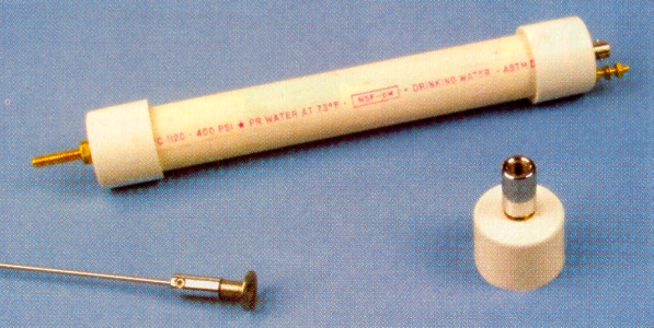
The active antenna is housed in a Schedule-40 PVC tube with connections at opposite ends for the wipe antenna element and the coax cable to the power supply and receivers.
Construction
You can build the antenna using readily available hand tools. The PC boards are available from FAR Circuits.(11) The only required adjustments are setting the power supply voltage to 24 V and setting the amplifier transistor bias for a source current of 53 mA.
Ql is special and available only from Crystalonics, which specializes in highperformance RF devices. Although the company usually doesn't sell single devices, it has kindly agreed to sell them to readers of this article.
PVC case
Prepare the pieces of Schedule 40 PVC pipe as follows:
Cut an 8 inch long piece of 1 inch Schedule 40 PVC pipe (the amplifier case). Drill a 1/4 inch hole in the center of a 1 inch PVC pipe cap. This will become the top of the amplifier case. Similarly, drill a 1/8-inch hole in the end of a 1 inch Schedule 40 pipe cap. Drill a 9/64 inch hole in the end of the cap near the edge, 0.50 inch from the center. Countersink this hole for a #6 brass flathead grounding screw. Cut two 1 inch long pieces of 1/2 inch PVC pipe to act as spacers at the top and bottom of the printed-circuit board.
Place the BNC connector in the pipe cap via a 1/8 inch hole with the connector facing outward. Solder a short piece of #24 bus wire (approx) to the head of a #6 x 1 inch brass screw. Install the screw with the threads facing out. Solder the wire to the ground tab of the BNC connector. Solder a 1.5 inch piece of wire to a 1/4 - 20 x 1.5 inch brass bolt. Install it in the other PVC cap and seal it with Permatex Silicone Windshield and Glass Seal, available at auto parts stores, to seal the bolt, nut and washers to the PVC cap. This sealer is thinner than regular silicone sealer and flows into cracks and crevices for a better seal.
Note that the RadioShack BNC chassis connectors specified for this project are different than common chassis connectors. They have a small solder lug on the edge of the ground side that is used to connect the ground side of each signal line from the printed circuit board. The ground tab cannot be bent out to make soldering easier. It will break off.
Tip: When mounting a BNC connector in plastic, apply a few drops of super glue (cyanoacrylate cement) to the edge of the connector next to the plastic. Rotate the connector a turn or so to distribute the cement along the joint where the connector meets the plastic. Tighten the nut and the connector will bond into place. While in service, the connector will not rotate when the bayonet connectorring is engaged or disengaged.
Place the two end caps on the 8 inch piece of pipe and make two small marks where the pipe caps meets the edge of the pipe when fully seated. Use these marks during final assembly to make sure that the caps are well seated on the pipe.
Heat Sink
Refer to figure 2 while building the heat sink. Cut a 4.5 inch piece of 3/4 inch copper pipe. On one end cut two slots 1/2 inch long spaced 1/8 inch apart. Place the assembly in a vise and cut off ½ inch of the end of the pipe; leaving a tab. Do this by cutting around the pipe so that the tab remains between those slots. The tab that remains should be 1/2-inch long and 3/8 inch wide. This tab will contact the transistor case to help dissipate heat.
Cut two slots 1/4 inch deep and 180° apart on the tab end, placing the tab halfway between the slots. Cut two more slots on the opposite end of the pipe at the same position as the slots on the tab end. The metal next to these slots will be bent inward slightly to hold the PC board in place.
To keep the copper heat sink from rattling against the PVC pipe enclosure, cut six 1/4 inch deep slots on each end to form six small tabs. Bend these out slightly, as shown in figure 5.
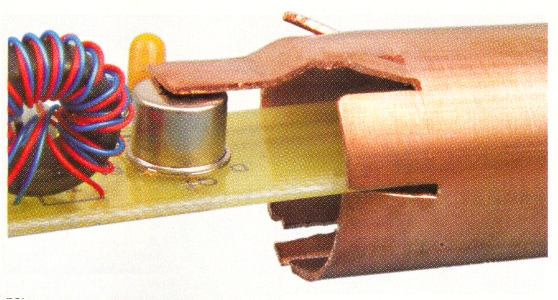
Figure 5 - Use the needle nose pliers to bend the heat sink tab so it lays flat on the transistor case. Carefully bend the tab to maximize contact.
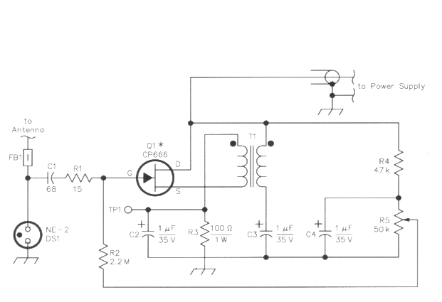
Figure 6 - Active antenna schematic. Unless otherwise specified, resistors are 5%-tolerance carbon-composition or metal-film units.
- C1 - 68 pF ceramic capacitor, 2 kV
- C2 - C4 1 µF, 35 V tantalum
- DS1 NE-2 neon lamp
- FB1 - Ferrite bead, Amidon FB43-287.
- J1 - BNC jack
- Q1 - CP-666 JFET (Crystalonics Inc, 17 A St, Burlington, MA 01803; tel 781-270-5522, fax 781-270-3130; www.crystalonics.com. When ordering, refer to this QST article. International orders accepted. Price: $14.75 plus shipping.)
- R1 -15 Ω; see text.
- R2 - 2.2 MΩ.
- R3 - 100 W, 1 W
- R4 - 47 kΩ
- R5 - 50 kΩ potentiometer.
- T1 - 17 bifilar turns #30 AWG wire wrapping wire (278-501) wound on, an Amidon FT50-75 or FT50-J core.
Active antenna PC board
The antenna's schematic is shown in figure 6. Make the wideband transformer by twisting two 18-inch-long pieces of #30 wire wrapping wire together. The wires should be different colors so they can be identified after winding. Wind 17 turns of the bifilar wire on the Amidon FT-50-J or FT-50-75 ferrite core. Note that the first time the wire passes through the center of the core counts as turn number one. Each additional time the wire passes through the core is considered an additional turn. The transformer design was optimized to avoid core saturation at maximum signal levels while having good VLF response. Adding turns will degrade the intermodulation performance. Sensitivity at 10 kHz is quite adequate.
Insert and solder the parts. Insert the wideband transformer wires so that the lead from the start of each winding is inserted in the PCB holes identified with the dots. Insert the lead from the finish of each winding into the PCB transformer holes without the dots, keeping the primary and secondary windings connected as in figure 6. Use different wire colors to distinguish the primary and secondary wires. When the PCB is completed, wideband transformer T 1 can be secured to the board using a dab of silicone sealer.
Positioning the assembly on a hard, flat surface, carefully flatten the heat sink tab with a hammer. Slide the heat sink over the PC board and, using needle nose pliers, twist the pipe in at the slots under the heat sink so the board rests on the "shelf." See figure 4.
Use the needle nose pliers to bend the tab so it lies flat on the transistor case. Carefully bend the tab to maximize contact. See figure 5. You may need to remove, adjust and replace the parts several times to get the tab positioned correctly. This part of the assembly is very important! Be patient and be sure to get this right so the transistor doesn't burn up. The slots on the opposite end are bent inward slightly to form another "shelf." This shelf will press in the opposite direction and cause the PC board to bend slightly so that the PC board acts as a spring and holds the transistor against the heat sink tab.
Slide the 8 inch piece of PVC pipe over the PC board. Adjust the three small tabs on each end of the heat sink (shown as "A" on figure 2) to make the heat sink, snug inside the pipe. Remove the PVC pipe and set it aside. Solder a 4 inch long piece of wire to the antenna pad of the PC board. Wind the wire through the holes near the pad to relieve the strain on the solder pad. Use a small dab of silicone to secure the wire in the holes. Solder two 4-inch pieces of wire (different colors) to the signal connector pads, on the other end of the PC board. Wind them through the nearby holes to act as a strain relief for the solder pads. Use a small dab of silicone to secure the wires in the holes.
Slide a 1 inch long piece of 1/2-inch PVC pipe over the signal leads. Check the fit over the ground screw and file a clearance area on the edge of the spacer, if needed. Now trim and connect the signal leads to the BNC connector in the PVC pipe cap. Use small dabs of silicone sealer on the BNC connections to seal them and to provide strain relief.
Slide the 8-inch PVC pipe over the PC board and down into the BNC connector pipe cap. Place the other 1 inch long piece of 1/2-inch PVC pipe over the antenna end of the PC board. Make sure that everything fits and that the antenna end pipe cap will fit in place properly.
The transistor bias needs to be adjusted, so set the active antenna assembly aside without cementing the pipe caps in place at this time.
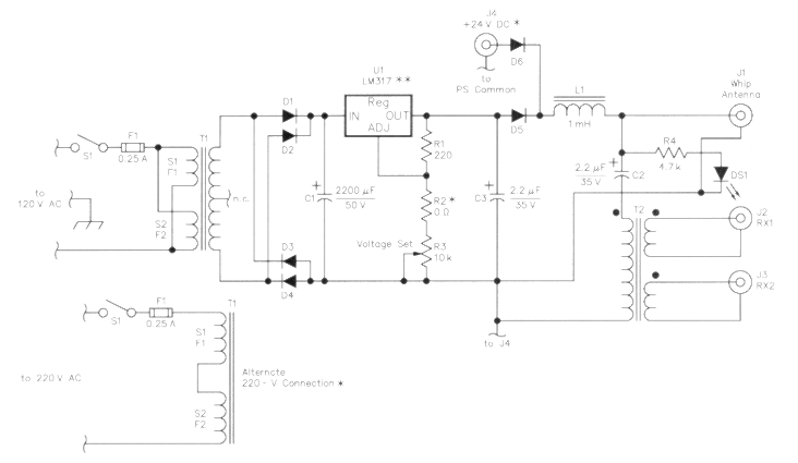
Figure 7 - Power supply schematic for the AMRAD active antenna. Unless otherwise specified, resistors are 1/4-W, 5% tolerance carbon-composition or metal-film units.
- C1 - 2200 µF, 50 V
- C2, C3 - 2.2 µF, 35 V tantalum.
- D1 - D6 - 1N4003, 200 PIV, 1 A
- DS1 - LED
- F1 250 mA AGC
- J1 - J3 - BNC jack
- J4 - Coaxial power jack
- L1 - 1 mH choke, 100 mA.
- R1 - 220 Ω
- R2 - Zero Ω resistor or jumper wire.
- R3 - 10 kΩ multiturn potentiometer
- R4 - 4.7 kΩ
- S1 - SPST toggle
- T1 - 24 V transformer, split-bobbin design.
- T2 - 20 trifilar turns #30 AWG wirewrapping wire wound on an Amiclon FT50-75 or FT50-J core.
- U1 - LM317 adjustable voltage regulator, TO-220 package
- Heat sink, TO-220
Power supply
Assemble the power supply board. The schematic is shown in figure 7. The wideband transformer consists of 20 turns of trifilar wire on an FT-50-J or FT-50-75 Amidon ferrite core. Three pieces of #30 wire wrapping wire are twisted together to make a trifilar winding. Again, using different-color wires will make finding the individual windings much easier to identify.
Attach 2-inch leads to each of the antenna signal leads, RX 1 and RX2, and the battery plus and minus. Attach an LED on 2 inch leads to the LED pads on the PC board. Once the power supply PCB is installed in the case, these leads can be soldered onto the connectors and the LED.
The RadioShack cases have molded card guides that interfere with the BNC connector mounting nuts. Remove these card guides with a sharp wood chisel and hammer. This flattens the inside surface. Prepare the case with the connectors positioned near the leads that connect to them. Place the fuse and power switch as far away from the rest of the circuitry to minimize coupling capacitance.
Assemble the printed circuit board into the power supply case and solder the wires to the connectors and the ac power. Note the polarity of the antenna connector, apply power and check the voltage on the antenna connector. Adjust the VOLTAGE ADJUST potentiometer until +24 V appears on the center pin realtive to the outer shell.
This completes the power supply assembly and checkout.
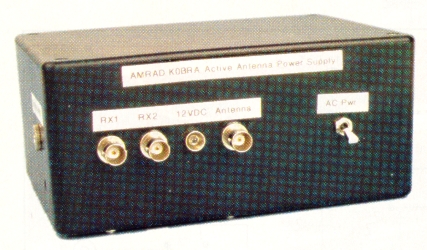 |
The active antenna power supply enclosure with BNC jacks for the coaxial cables to the active antenna and receivers. |
Initial test and checkout
Remove the PVC pipe from the active antenna to gain access to the bias potentiometer. Adjust the bias potentiometer, R5, so that the wiper is at ground potential.
Method 1: Temporarily connect the active antenna to the power supply while running the center conductor (a clip lead, etc) through a milliameter. Adjust the bias for a current of 53 mA.
Method 2: Connect the active antenna to the power supply using a BNC cable. Put a voltmeter across R3 on the printed circuit board. Adjust the bias potentiometer, R5, for a voltage of 5.3 V.
If you have the equipment necessary to measure second-order intermodulation values you can fine-tune R5 to obtain the best performance. On the four units we tested, the optimum current was only 2 mA above or below the design value of 53 mA.
This completes the setup of the active amplifier.
Connect the active amplifier to the power supply with a BNC cable. Let the amplifier warm up while checking the transistor case temperature. It should be only slightly warm to the touch, showing no more than a 10° F temperature increase over that of the heat sink. If needed, place a thin coating of heat sink grease on the top of the transistor to reduce the thermal resistance. Use only a slight amount of grease as it can become fluid and drip onto the PC board and components on a hot day.
Use small dabs of silicone sealer at the four points where the heat sink tabs contact the PC board to secure the heat. Install the PVC pipe onto the amplifier. Place the 1 inch long piece of ½-inch PVC pipe over the wire from the printed circuit board. Slide a ferrite bead over the wire. Use a short piece of insulated sleeving to slide over the solderjoint and solder to the wire from the top cap. Shape the wire into a springy coil so it will fit into the standoff tube. The top cap can now be slid over the PVC pipe. Use the mark on the pipe to make sure that the cap is fully seated and not pinching the antenna wire. Use caution when rotating the pipe caps during assembly or disassembly so the wire leads remain untwisted.
The assembly is now ready for outdoor testing with an attached whip. Connect a BNC coaxial jumper between the active antenna and the antenna connector on the power supply. Caution: Connect only the active antenna to the power supply connector. Receivers and other devices can draw excessive current and burn out L1 or damage the connected equipment. If, when connected, the choke burns out, the LED on the power supply will not light up. You may want to wrap a piece of colored tape near the end of the coax going to the active antenna to identify it as the correct cable. Connect a receiver to the RX 1 or RX2 connector.
You should hear AM broadcast and HF signals. LF signals and noise should be heard when the receiver is tuned to the LF range. When you're satisfied that everything is working properly you can take down the antenna and seal the assembly.
Final Assembly
Once the caps are properly seated the amplifier can be sealed using silicone. Permatex Silicone Windshield and Glass Seal is thinner and will fill joints better than the more familiar silicone caulking. Seal around the top bolt, the top and bottom cap and the ground screw. After the goop hardens overnight the antenna amplifier is ready to install. To regain access to the printed circuit board, peel the silicone sealer from around the edge of the pipe caps and force them off the PVC pipe by hand.
Several different whips can be used on the active amplifier. Short automobile replacement whips made to attach over the stub of a broken auto antenna can be found in most auto parts stores. 1 m stainless steel whips are available.
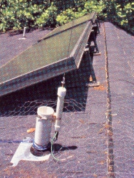
Siting and installation
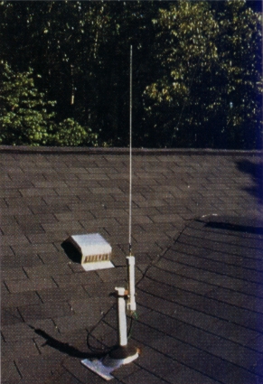
This small antenna can be mounted almost anywhere, but an electrically quiet site will produce the best results. Roof-top vent pipes work well because the PVC vent pipes and the PVC antenna housings camouflage one another. Thin whips also disappear at a distance.
Use the ground screw next to the antenna BNC connector to establish a quiet ground reference for the antenna. This ground usually works best if it's not connected to any other ground. Testing various ground rod locations while monitoring LF noise on the receiver can help you pinpoint the best location for minimizing received ac power-line noise. Because of the low capacitance of the antenna and the coupler, a 12 inch ground rod may be satisfactory. A sheet of chicken-wire screening can be laid beneath the antenna and connected to the antenna ground to stabilize the fields around the antenna to further reduce noise coupling. Chicken-wire screening in rooftop installations is generally hard to see from the ground.
One source of intermodulation of which the US Navy is especially aware is the "rusty bolt" effect. When a corroded joint exists between two pieces of metal, the joint can act as a nonlinear junction. In a strong RF field, the corroded junction creates intermodulation between the strong signals. On a ship (with its many transmitters) or in an area with several strong AM broadcast stations, the intermodulation is reradiated and receiving antennas, including this active antenna, can pick it up. This problem appears as LF carriers that have two sources of audio modulation. When these carriers are tuned in with an AM receiver, it sounds as though two stations are talking simultaneously. If this problem occurs, move the antenna or find and clean the offending joint.
A block of wood with wedges cut in it can be used between the antenna and a mast. Use a stainless steel hose clamp to secure the assembly. Avoid placing metal hose clamps or other metal objects near the upper half of the antenna as nearby metallic objects can add to the input capacitance and slightly degrade the antenna performance.
Keep the coax run to the shack insulated from any grounds as it wends its way to the power supply. With such low capacitance between the power line and the receiver grounds, it's important to minimize parasitic, noise coupling in the antenna ground circuit by keeping the line away tops other grounds and power lines.Best LF performance is obtained if the antenna whip is higher than nearby conducting objects. Imagine pulling a giant plastic sheet over your house and yard. The whip should be above this imaginary sheet. A more accurate (and much more complex way to think of it is to imagine a large metal sheet several hundred feet above your house and yard (play along). Now imagine that the sheet is charged with a high dc voltage. If you were to examine the electrostatic field around and above your house and yard, you would discover those points below the plastic sheet are at a 0 V field potential.
LF signals have very long wavelengths at 136 kHz, 1 wavelength is 7181 feet. At these wavelengths, the average suburban yaard is less than 1/10 wavelength across, so an electrostatic field may be used to approximate LF waves. Thus, at LF, those areas with a zero electrostatic field will also have a zero, or near-zero LF field strenght. The freely downloadable student version of the QuickField Finite Element analysis program (quickfield.com)can be used to plot the electrostatic field around a simple house and yard model.(13) Or as mentioned above, simply visualize the plastic sheet and make sure the antenna isn't mounted "underneath" the imaginary, boundary.
Measuring field strength
This active antenna has reasonably reproducible sensitivity when the PC boards and listed parts are used. This makes it possible for you to measure signal strength in volts-per-meter, which means that the overall efficiency of an LF antenna can be measured rather than estimated.
Using a receiver S-meter and a signal generator, the signal voltage from the antenna can be measured by substituting the signal generator for the antenna and adjusting the signal generator to get an identical S-meter reading. A selective voltmeter that can directly indicate the voltage at a received frequency is even better. Once the antenna output voltage is known, the field strength can be calculated by using the antenna factor, which is added to the antenna-voltage reading, to give the field strength in volts-per-meter. When using the antenna for measuring field strength, avoid using any metal clamps or other metal around the upper half of the antenna.
If you are using dBm to express voltage and dBµV/m (dBµV/m = dB above 1 microvolt per meter) to express field strength, the antenna factor is -16.5 dBµV/m. If you want volts-per-meter, multiply the measured voltage by 6.683 to convert to volts-per- meter. This antenna factor is accurate (for this antenna) between 20 kHz and 26 MHz (see figure 1). Keep in mind that this isn't an individually hand-calibrated EMC antenna, so use the results with care. Above 10 MHz, measurements become questionable with any E-field antenna and become more subject to minor construction variations.
Variations on a theme
If low-band VHF or TV Channels 2 or 3 are particularly strong in your area, you may need to add two or three ferrite beads on the wire between the amplifier and the whip. These added beads roll off the response starting at about 10 MHz rather than 30 MHz, providing greater attenuation at the low-VHF range. In place of using R 1, another choke can be added to further reduce the higher-frequency response.
If connector confusion could lead to connect 24 V where it shouldn't be, substitute an F, TNC or Mini-UHF connector for the antenna BNC connector.
The length of the PVC pipe can be made longer and the whip contained inside along with the PC board. It then can be mounted on a windowsill and disguised as a flagpole to hide its true purpose. If you require less capacitive coupling to the power line, you may be interested in knowing that we tested a Tamura 3FL30-200 transformer and found a capacitance of only 14.7 pF between the two 120 V primary windings. If this model is used as an outboard isolation transformer, the combined capacitance between the power line and the dc supply is reduced to only 9.25 pF. This applies only if you are using the 120 V connection. We haven't yet seen the need for such a low capacitance, but it's comforting to know there is a solution if one is needed.
A sheet of chicken-wire screening can be laid beneath the antenna and connected to the antenna ground to stabilize the fields around the antenna to further reduce noise coupling. Chicken-wire screening in rooftop installations is generally hard to see from the ground.
Acknowledgments
Many people helped with this project, and the AMRAD lunch crowd attendees who eat tacos and talk Amateur Radio at 12:30 each Saturday at Tippy's Taco House in Merrifield, Virginia, certainly contributed their share. Come by and see us and talk about LF while chowing down on a basket of tacos. Thanks go to Ralph Burhans, who set out a clear discussion of active antennas in his writing; Chuck Rippel, WA4HHG, who provided key comments and encouragement; Steve Ratzlaff, AA7U, who provided a number of useful suggestions on the design and conducted the antenna's intermodulation testing. And finally, Dallas Lankford must be recognized for providing key help on the design, especially the CP-666 transistor.
Notes
- Dick Goodman, WA3USG, "The Monster Loop," QST, Sep 2000, pp 38-40.
- Bill Farmer, W3CSW, "Attic Loop Antenna," AMRAD Newsletter, Nov-Dec 1999, pp 4-5; available at the AMRAD Web site LF page.
- Ken Cornell, W2IMB, "Varactor Tuned Remote Active Antenna," The Low and Medium Frequency Radio Scrap Book, 8th Edition, Ken Cornell, Point Pleasant Beach, NJ, 1992.
- Andr Kesteloot, N4ICK, "A Remotely-Tuned Active Antenna for LF," AMRAD Newsletter, Nov-Dec 1998, p 10.
- Ralph Burhans, "All About VLF Active Antennas," Radio- Electronics, March-June 1983, pp 63-68.
- Ralph Burhans, "Active Antenna Preampliflers," ham radio, May 1986, pp 47-54.
- Frank Gentges, K0BRA, "Annapolis Report," AMRAD Newsletter, May-Jun 1999, pp 8-10.
- Private e-mail with Dr Dallas Lankford, Professor, College of Engineering and Science, Louisiana Tech University.
- Frank Gentges, K0BRA, "Modifying the RX-320 Receiver for LF/VLF Operation," AMRAD Web site LF page.
- Receiver Performance Tests," The 2001 ARRL Handbook for Radio Amateurs, p 26.45.
- Hybrid Combiners for Signal Generators," The 2001 ARRL Handbook for Radio Amateurs, p 26.40.
- FAR Circuits, 18N640 Field Ct, Dundee, IL 60118-9269; tel 847-836-9148. Price: $8.50 per set plus $1.50 shipping for up to four boards.
- Frank Gentges, K0BRA, "How Low is LF? AMRAD Technical Symposium 2000, pp 69-79.
K0BRA.