What can you do with a dip meter?
Quite a bit! The dipper is one piece of test equipment that can replace a whole shelf of expensive gear-if you know how to use it.
As radio amateurs we are often interested in resonance. What is the resonant frequency of that antenna I just put up? is that trap resonant at the frequency I think it is? That crystal, the one with the strange markings, is it good for anything? Do I have an inductor in the junk box that will work in the next project? How do I find the value of those mica capacitors with the cryptic markings? Is that chunk of coax really a 1/4 wavelength at the frequency I hope it is?
These are all questions that can be answered by using a dip meter or "dipper" to measure resonance-just one of the instrument's many uses. A dipper makes a very sensitive absorption wave meter for measuring a signal frequency. Since a dipper is an oscillator, I have used it as a signal source to troubleshoot receivers, as well.
All this versatility comes at a price; a dip meter is not a precision instrument. There are techniques to reduce errors to acceptable levels, which will be discussed later. In case you haven't guessed by now I am a big fan of dip meters-mine has allowed me to make many tests that would normally require an extensive array of laboratory equipment.
What is a dip meter?
A dip meter is nothing more than an oscillator with the frequency-determining coil exposed, so that it may be coupled to other electrical circuits. A frequency control is included so the oscillator's approximate frequency is known and can be adjusted. A meter indicates the level of oscillation. Most dip meters come with a set of plug-in coils for wide frequency coverage in several ranges. Older vacuum tube units, in which the meter monitored the grid current of the tube to indicate the level of oscillation, were called grid dip meters. With the availability of high frequency transistors, dip meters went high-tech and battery operation became practical.
The typical dip meter is contained in a small case, with provisions for external plug-in coils. A dial to control the oscillator frequency will be conveniently located on the unit. The meter is located for easy reading while the frequency is being adjusted. Most dippers will also have a control to adjust the level of oscillator activity. This control allows the operator to keep the meter indication at a convenient level over a wide frequency range. If it is a solid-state unit, a battery is included in the case, while vacuum tube units will have an ac power supply that may be self-contained or separate.
Sometimes there is a switch to kill the oscillator to facilitate its use as an absorption wave meter. On others it is possible to turn the activity control down far enough to stop the oscillator. On the front panel there may be an audio output to listen to the modulation of a carrier.
Using the dipper
When the coil of the dipper is placed near the resonant circuit under test, some of the energy from the oscillating dipper is coupled to the circuit. This coupling reaches a maximum when the frequency of the dipper and the resonant frequency of the circuit are the same. This coupled energy is supplied by the dipper's oscillator, which causes the amplitude of the oscillation to drop. Since the meter indicates oscillation level, a pronounced dip in the meter will be seen as the dipper is tuned through the resonant frequency of the circuit. The oscillator frequency at the minimum or bottom of the dip is the frequency of resonance of the circuit under test. The nice thing is that the circuit being tested does not have to be powered up to measure its resonant frequency.
Placing the axis of the dipper's coil adjacent and parallel to the axis of the coil in the circuit under test results in inductive coupling. This method gives the deepest and most easily found dip on the meter. The dipper's oscillator frequency is "pulled" by the additional load of the resonant circuit-this is one of the major sources of error in making dip meter measurements. Reading the dipper frequency with loose coupling will reduce this error to acceptable levels. After the dip is found I decrease the coupling (move the two coils apart) and recheck the frequency of the dip.
A variation of inductive coupling is link coupling. This allows the dipper to be coupled to circuits in some very cramped places. The link I use is a 2-foot length of coax with a two-turn coil on each end. As the frequency of interest increases, links with fewer coil turns on each end should be used. Two turns can be used up to 70 MHz. Couple one link to the dipper and the other link to the circuit under test.
Capacitive coupling, in which the axis of the coil is perpendicular to the item under test, is useful when there is no inductor present or it is difficult to get to, such as with an antenna. Using capacitive coupling usually produces a shallow dip that is more difficult to see as the dipper is tuned.
Finding the resonant frequency of an LC circuit
Coupling the dipper's coil to the circuit under test, inductive coupling will produce an easily found dip as you tune the dipper through its frequency range. When you find a dip, move the coils apart to reduce coupling. If the depth of the dip does not decrease, you may find the dip is internal to the dipper. I usually move the coils apart so the dip is no more that 20% to 30% of the maximum meter reading. Loosening the coupling to this point prevents the circuit under test from pulling the dipper's oscillator too badly, and the resonant frequency may then be read off the dipper's dial with a fair degree of confidence.
Can't find a dip? The LC circuit could be outside the range of your dipper. It is helpful to have an idea where to expect resonance and to tune slowly. Occasionally I have found the coil under test to be open, or the resonating capacitor to be faulty, when I could not find a dip. A good way to gain some confidence in using your dipper is to make a parallel resonant circuit from a coil and capacitor. Support the circuit on a nonconductive surface. Practice coupling to the coil of the resonant circuit in every manner you can think of and note the characteristics of the dip.
Finding the value of an unknown inductor
Connecting a suitable capacitor of known value in parallel with the unknown inductor creates a resonant circuit. Using the dipper you can now find the resulting resonant frequency. I keep fixed-value 5, 20, 100 and 200 pF mica capacitors with my dipper just for making resonant circuits. I also have a calibrated 100 pF variable capacitor for doing quick checks on inductors.
Once resonance has been found, the value of the inductor can be found from the following equation:
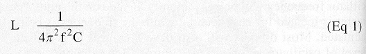
where
π=3.1416
f is in MHz
C is in µF, and
L will be calculated in µH
Since I dislike doing the math, I have acquired two circular slide rules that will solve resonance problems. Some textbooks have resonance nomographs that can be used. [Chapter 6 of The 2002 ARRL Handbook contains a reactance chart that can be used for this purpose.-Ed.]
If you check the same inductor at different frequencies, you will get slightly different values due to the distributed capacitance of the inductor. If the inductor has a metal core, this will also cause inductance to vary with frequency. It is best to check inductors near the frequency of intended use.
Finding the value of an unknown capacitor
As with the unknown inductor, form a resonant circuit with the unknown capacitor using an inductor of known value. A good source of inductors is the plug-in coils that came with the dipper. As described in the preceding section you can find the inductance of the coils and use them as your inductance standards. To avoid soldering the plug-in coils to capacitors, I found that Mueller makes some alligator clips that slip over the pins of my dipper coils just fine.
Once you find the resonant frequency of the circuit formed with unknown capacitor and known inductor, calculate the value of the capacitor as follows:
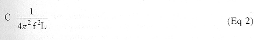
where
4π^2=39.48
f is in MHz
L is in µH and
C is calculated in µF
The frequency range of the dipper and the values of the known inductors limit the range of capacitance values that dippers can measure. The largest value of capacitance that can be measured is usually about 1 nF (1000 pF).
Finding Q of an inductor
The Q (or Quality Factor) of an inductor is a figure of merit for an inductor. For example, Q is an indication of how sharply a resonant circuit formed with this inductor will tune. There is a good explanation of Q in chapter 6 of The 2002 ARRL Handbook. Form a resonant circuit with the inductor to be tested and a mica capacitor. Since the Q of a mica capacitor will be in excess of 1200, the resultant Q of the resonant circuit will be almost totally dependent on the Q of the inductor.
An estimate of Q may be obtained in the following manner. After noting the frequency F and the depth of the dip at resonance, tune the dipper higher in frequency until the dip has been reduced by 30%-this is frequency F1. Now tune lower back through the dip to where the dip has again been reduced by 30%. This frequency is F2, Calculate Q using the following equation:
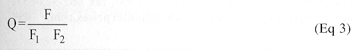
To make a precise measurement of the frequencies involved, I track the frequency of the dipper with a calibrated receiver as discussed in the section on measuring crystals. Obviously the results are highly operator-dependent but are good enough to difference between a coil with a Q of 20 and one of 50.
Measuring quarter- or half-wavelength transmission lines
The physical length of 1/4 wavelength of a coaxial cable may be calculated using the following
equation:
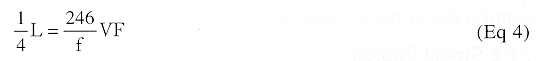
where
VF is the velocity factor of the coaxial cable (assumed to be 0.66).
f is in MHz and
length is in feet
To prepare a ¼-wavelength section of cable, calculate the length of cable using Equation 4 (including the length of any connectors or adaptors), add a few percent and cut. Short each end of the cable (with a wire of the smallest possible length), then couple the dip meter to one of the shorts and look for the lowest frequency dip. This is the frequency at which the cable is approximately ¼ wavelength long. It is slightly short, due to the detuning effect of the loop. Page 27-8 of The ARRL Antenna Book describes a more accurate method that replaces the loop with a parallel tuned circuit that resonates at the desired frequency. If you need a half wavelength section, you can use the ¼-wavelength technique at half the desired frequency.
Measuring crystals
A crystal's resonant frequency can be found by inductively coupling it to the dipper. I keep several different types of crystal sockets around with two turn loops soldered to them. It's then a simple matter to couple crystals to the dipper. The Q of a crystal is very high, so the dipper must be tuned slowly and watchfully. Because of the high Q, the dipper's frequency may be pulled significantly. For this reason I listen to the dipper on a receiver during the tests (Figure 6). A foot or two of wire lying in the area of the dipper and hooked to the antenna terminal of the receiver is enough coupling. Be sure the BFO of the receiver is on. The crystal frequency found by this method will not be exact but will usually be within 0.2%. The crystal's frequency can be specified only to operate in a circuit with a specified capacitance.
Sometimes a dip will be found at a frequency that doesn't make sense. You may be checking an overtone crystal. Check other harmonically related frequencies for a dip. Even crystals not intended for overtone operation will usually show some activity near their odd overtones.
As a tuned detector
Most dippers may be used as detectors by turning the oscillator completely off or by turning the activity control down to the point that oscillation just stops. In the first case the dipper will act as a diode detector and in the second case as a regenerative detector. The approach you use will be dependent on the features of dipper.
Many times I have found that a superheterodyne receiver was not functioning because the local oscillator was dead or off frequency. If you are suspicious of an oscillator, dig out the dipper. Couple the coil of the dipper to the oscillator coil. With the dipper in the detector mode, tune the dipper and look for an upward deflection of the dipper's meter as the frequency of the oscillator is found. If there is no upward deflection, the oscillator may not be doing its thing.
For those of us with vacuum tube power amplifiers, the dipper acting as a detector is an excellent indicator of parasitic oscillations that require neutralization. Follow the manufacturer's instructions and be aware that tube amplifiers use lethal high voltages.
Many times we would like to check the operation of a transmitter that has an integral antenna. Radio control models and garage door openers are some examples. A dipper acting as a detector can serve as a field strength meter to check the frequency and level. If your dipper has an audio output, you can confirm the carrier is being modulated, as well.
As a signal source
Since a dipper is a tunable oscillator, it can be used as a signal source to align or troubleshoot a receiver. It Will never replace the RF generator but when nothing else is available, it will do. To adjust the signal level, vary the activity control and the coupling to the dipper coil.
Measuring Impedance
Heathkit, Millen and Eldico made impedance bridges designed to be driven by a dipper. Since these bridges have no means of compensating for reactance, measurements are best made at the frequency of resonance. The range of these bridges is around 10 to 400 ohms.
Sources of dippers
Eico, Heathkit, Millen and Measurements Corporation models show up at ham flea markets fairly often. Even some military surplus units are sometimes seen. Pricing seems to be from $3 to $50 depending we the condition and desirability of the particular model involved. If you are looking for a small useful project, why not build, a dipper? The 2002 ARRL Handbook has construction information in chapter 26. Coil forms are available from Antique Electronic Supply.(1)
Summary
I hope the information presented here wil I create some interest in dippers in general and MI stimulate the discovery of other applications. For those of us who must pursue our amateur radio activities on a tight budged, the dipper represents great value for the dollar. The dipper is not inherently extremely accurate but with good technique and attention to detail, errors can be reduced to acceptable levels.
notes
- Antique Electronic Supply, 62a S Maple Ave, Tempe, AZ 85283, tel 480-820-5411, fax 800-706-6a.16 (US and Canada) or 480-820-4643; www.tubesandmore.com/; info@tubesandmore.com
K6TAF.