Simple Transverter for 24GHz
A simple DSB-Transverter for 24GHZ utilizes a subharmonic mixer with the new low-cost microwave diodes BAT15-03W from Siemens in a SOD-323 plastic package. An output power of 0.5mW and a DSB-noise figure of 8dB can be achieved. This techniques reduces the complexity of a 24GHZ-transverter considerably.(5)
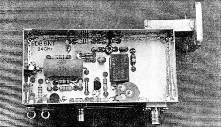
Figure 1: 24GHz Linear Transverter
1. Design
The circuit digram (Fig. 2) shows a subharmonic mixer, which is driven from a LO on 12GHz. The mixer translates a signal from 144MHz to 24.192Ghz in transmit and serves as a DSB receive converter also. An IF-amplifier and the T/Rswitching is integrated.
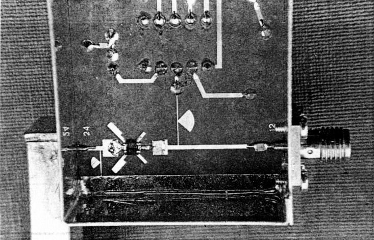
Figure 2: 1.3GHZ Transverter (Top View)
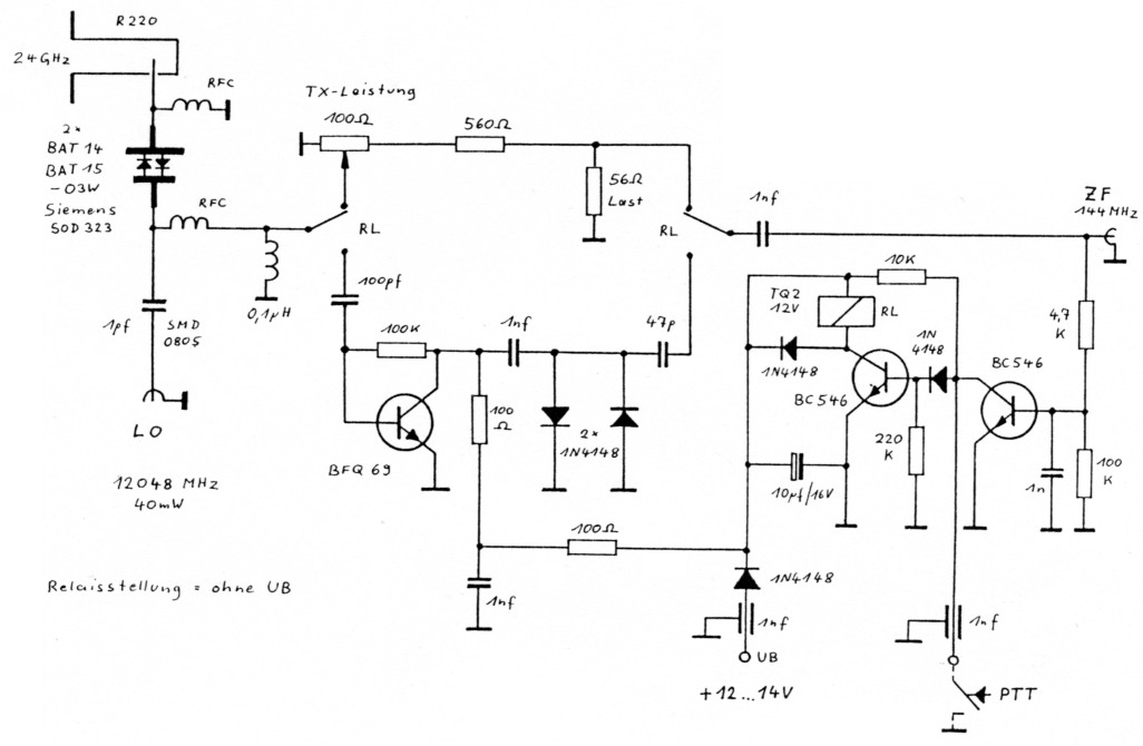
Figure 3: Circuit Diagram
2. Construction
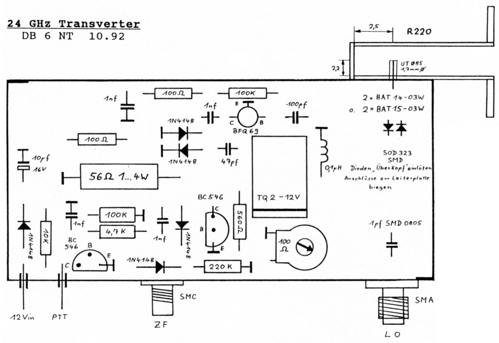
Figure 4: Parts Layout
The construction is straightforward (See. fig. 2&4):
- Trim the PCB to the dimensions of the tinned box and drill all holes
- Drill the holes for the coax connectors (144 mm off the edge and 3.3mm diameter
- Drill the hole for the waveguide launcher (Diam. 1.7mm)
- Drill the holes for the feedthrough-caps (3.3mm diam.)
- Mount the coax connectors
- Put the PCB onto the center conductors of the coax connectors and solder carefully from both sides to the tinned box
- Mount all parts. The 24T15 should be mounted 'overhead' with leads bended downwards. The diodes must be flat on the PCB.
- A piece of waveguide(R220) with a flange must be drilled 2.5mm from the open side with 1.7mm diameter for the launcher which is made from a piece of stripped UT-85 semirigid. This should have a free length of 2.2mm in the waveguide and must be soldered to the stripline an the other end. Afterwards the waveguide can be soldered to the side of the tinned box.
| Anzahl | Bezeichnuna/Type | Bauform | Herst./Bezuasquelle |
|---|---|---|---|
| 2 | Schottky-Dioden BAT15-03W | SOD-323 | Siemens |
| 1 | Transistor BFQ69 | T-Plastic | Siemens |
| 2 | Transistor BC546B | Plastic | Siemens |
| 5 | Dioden 1N4148 | Glas | Diverse |
| 1 | Relais SDS TQ2-12V | SDS/Burklin 30G7556 | |
| 1 | Keramik-C 47 pF NPO | EGPU | Diverse |
| 1 | Keramik-C 100 pF NPO | EGPU | Diverse |
| 4 | Keramik-C 1 nF | EGPU | Diverse |
| 1 | ELKOIOuF/16V | 4x7mm | Diverse |
| 1 | Pot. 100Ohm | PTC 10 1v | Piher |
| 1 | Widerstand 56Ohm/4,5W | 0920 | Bürklin 29E636 |
| 2 | Durchf.-C 1 nF | 0805 | Diverse |
| 2 | Widerst. 100Ohm | 0207 | Diverse |
| 1 | Widerst.560Ohm | 0207 | Diverse |
| 1 | Widerst. 4,7kOhm | 0207 | Diverse |
| 1 | Widerst. 10kOhm | 0207 | Diverse |
| 1 | Widerst. 100kOhm | 0207 | Diverse |
| 1 | Widerst. 220kOhm | 0207 | Diverse |
| 1 | Drossel 0,1 µH | Siemens | |
| 1 | Koaxbuchse (SMA) | 4-Loch | Diverse |
| 1 | Koaxbuchse (SMC) | Diverse | |
| 1 | Weißblechgehäuse 74 x 37 x 30 | Schuberth | |
| 1 | Hohlleiter R220 | ||
| 1 | Flansch für R220 | ||
| 1 | Leiterplatte/PCB | 5870/0.25mm | DB6NT |
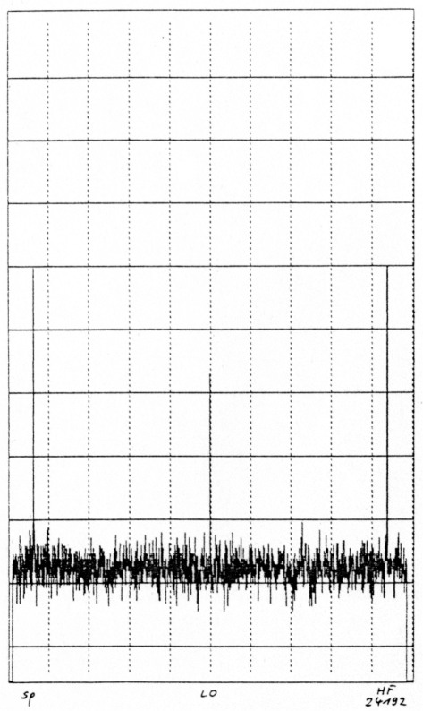
Bild 5: TX-Ouput Spectrum on 24GHz
3. Tuning
For tuning you have to perform the following steps:
- Apply voltage of 13.8V. The relais must switch.
- The following 2m-transceiver must indicate some increase in noise level
- Connect LO with at least 40mW of power on 12GHz. The noise level must increase even further.
- The mixer can be tuned by applying small stubs. This can be done in transmit mode by observing the power output. When output power is maximized also the noise figure will be optimum.
Tuning is not really necessary, because it will improve noise figure from 10dB down to 8dB and output power from 0.3mW to 0.5mW at most. Several replicates were measured with 10dB noise figure (DSB) and 0.3mW output.
Instead of the BAT15 also the BAT14 could be used. This diode gives somewhat more output power but the BAT15 is recommended because of the lower noise figure and uncritical behaviour.
If less than 40mW of LO-power is applied, the properties of the TVR will be degraded but it will remain functional. For the LO you can use the LO described in DUBUS(1). PCBs you can get from Dirk Fischer (Address see table 1).
No additional filter is necesary if the transverter is operated 'barefoot'. But if you want to add amplifiers for transmit and receive, some filtering of the image is necessary. The you can expect a further decrease of noise figure and for transmit the power amplifier must not deliver a high PEP-power because of the double tone excitation from image and transmit frequency.
4. Acknowl.
My special thanks go to Knut Brenndörfer, DF8CA, from Siemens for the special microwave semiconductors and also to Jürgen Dahms, DCODA, for his encouragement and the many experiments.
5. References
- M. Kuhne, "12GHz LO für 24&47GHz, DUBUS TECHNIKIII, pp. 149
- Wolf-Henning Rech, DF9IC, "47GHz SSB-Komponenten und Baugruppen", Dorsten 1989, Tagungsband, pp. 23
- E. Zimmermann, HB9MIN, "SSB-Millimeterwellen-Baugruppen für 24 und 47GHz", DUBUS TECHNIKIII, pp. 360
- Peter Riml, OE9PMJ, "High-Q Filter für die mm-Bänder", Tagungsband Dorsten, 1992, Anhang
- M. Kuhne, DB6NT, "Transistorized 24GHz Transverter", DUBUS TECHNIKIII, pp.343
- Jürgen Dahms, DCODA, "Aufbau und Abgleich eines einfachen 24GHz Verstärkers nach DB6NT", DUBUS TECHNIKIII, pp.352
DB6NT, Michael Kuhne.