Improving amplifier ALC circuits 1
Part One of this article examines current ALC techniques and illustrates methods of improvement. Part Two details several modifications (including ALC) for input matching and tube protection in the compact MLA-2500 amplifier. Editor
Grid current derived ALC helps upgrade AB2 amplifier performance
Although modern exciters contain adequate ALC circuits, modern AB2 amplifiers lack truly automatic practical circuits. In this article, several approaches to amplifier-developed ALC are examined and a practical circuit is developed, using a grid current derived sample. This circuit is used in a Dentron MLA-2500 to protect the 8875 tubes from overdrive and grid destruction. Adaptability to other tube types is also discussed.
One of the most important assets of a modern exciter is an ALC circuit that prevents overdrive of the exciter's final and intermediate stage amplifiers. Controlling the drive - or load - helps preserve spectrum space as well as the exciter's output devices. Few, if any, modern exciters lack ALC. Forward power, reflected power, final amplifier current, frequency and other parameters are used to set a power output level at which the exciter can operate without distortion or destruction. It is also true that few - if any - modern linear amplifiers have a satisfactory ALC circuit to prevent overdrive from occurring. This is so even though it is as important to control drive to an external amplifier as it is to control the drive to an exciter's final stage.
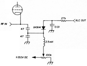
Fig. 1. Typical HF amplifier ALC circuit.
The term ALC is derived from early Collins nomenclature: Automatic Load Control. Many amplifiers include a circuit such as that shown in fig. 1. This circuit is clearly not automatic, but is based solely on RF input voltage. Such circuits offer protection from overdrive only when adjusted for each set of operating conditions on each band; they also offer no amplifier tube protection. Two important exceptions to the rule are amplifiers that do protect themselves from overdrive and consequent destruction when connected to the exciter's ALC: the Collins 30S-1 and the E.T.O. Alpha 77.
30S-1 ALC circuit
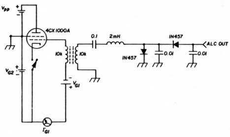
Fig. 2. ABA ALC circuit used in the Collins 30S-1.
An example of true ALC is the circuit used in the Collins 30S-1 amplifier (fig. 2). The 30S-1 is an AB1 amplifier; any grid current automatically indicates an overdrive condition. A 10K:10K transformer provides DC isolation between the ALC and grid circuits. In SSB service, an AC voltage is developed across the primary and secondary of the ALC transformer proportional to the grid current that flows at the audio frequency (rate) of the incoming signal. A substantial amount of control voltage is available for small values of grid current by using a voltage doubler circuit to rectify the AC voltage present across the secondary of the transformer. Sensing grid current variations is an effective way of preventing overdrive and distortion in this amplifier. The particular sensitivity of the circuit is achieved by the 10 kilohm impedance of the grid transformer. This high impedance in series with the grid can cause problems if the ALC voltage is not returned to the ALC buss in the exciter. Anyone who has ever heard a 30S-1 being used without the ALC interconnected can testify to the extraordinary bandwidth that results from even minimum overdrive when the grid voltage is subject to dynamic instability.
The 30S-1 circuit is not adaptable to most modern amplifiers in Amateur use. The most common circuits use zero-bias tubes operated in Class AB2. Significant values of grid current are necessary and normal. But there is an important analogy: just as the onset of grid current signals an overdrive condition in an AB1 amplifier, certain fixed amounts of grid current can signal overdrive or dangerous drive levels in an AB2 amplifier. It is quite possible to destroy a grid by applying drive without plate voltage being present. As the price of tubes soars, protective circuitry based on grid current seems a necessary adjunct for tube preservation alone even without consideration of performance.
E.T.O. uses this type of circuit. The Alpha 77 is a modern AB2 amplifier that has an ALC circuit designed to positively limit the 8877 grid current to 150-200 milliamperes (see fig. 3). Grid current is sensed, amplified, and inverted by the Q204, Q205 circuitry. In operation the negative ALC output voltage serves to limit the grid current to a preset, nondestructive limit even under conditions of mistuning, or worse, no plate voltage. In normal operation 150 milliamperes of grid current represents the upper limit of the tube's linear range.
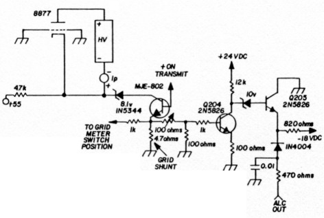
Fig. 3. AB2 grid-current-derived ALC circuit used in the E.T.O. Alpha 77 amplifier.
Modifying an older ALC circuit
The MLA-2500 amplifier ALC circuit shown in fig. 1 is representative of the majority of ALC circuits used in other amplifiers. The lack of protection for the grids of the 8875 tubes offers an opportunity to adapt a circuit that protects against overdrive and potential tube destruction. An added incentive is the fact that it costs as much to replace the final tubes in an MLA-2500 as to buy a used amplifier.
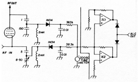
Fig. 4. Comparator-type ALC circuit derived from the Collins 30S-1 tuning and loading comparator circuit.
The first circuit I experimented with was based on the tuning and loading circuit of the 30S-1. Fig. 4 shows the comparator circuit which samples both input and output RF voltages to detect nonlinearity resulting from any cause. The use of DC amplifiers to generate a negative going ALC voltage when the comparator output voltage departs from its null seemed initially to be a satisfactory solution. In practice it failed. The impedance is fairly high and stray capacitance and inductance effects were different on each band. In addition, the circuit required correction to provide protection when the mode of operation was changed from SSB to CW which increased circuit complexity substantially. Disabling the circuit was also necessary in order to initially tune up. I soon abandoned this approach.
A working MLA-25O0 ALC circuit
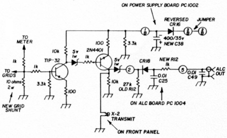
Fig. 5. Final circuit as installed in Dentron MLA-2500.
Fig. 5 shows the final circuit that was developed for the MLA-2500. It operates solely through the sensing and control of grid current. I had observed non-linearity in several different sets of tubes at more than 55-60 mA of grid current. After reviewing the tube specification sheets it soon became apparent that I could prevent overdrive and tube destruction by simply limiting exciter drive to 60 mA grid current under all conditions. The key to the circuit was a simple change in the value of the grid shunt. The new value was chosen to develop 0.6 VDC at 60 mA grid current, i.e., 10 ohms. A series multiplier resistor had to be added to the metering line. By using a 1-kilohm meter multiplier, full scale grid current was changed from 1 ampere to 100 mA. I modified the existing MLA-2500 ALC and power supply boards taking advantage of existing parts and wiring. Fig. 6 shows the construction technique used for the remaining components added. Fig. 7 shows the actual installation in the MLA-2500. The open area beneath the meter/function switches offered enough space to mount the component strips. After installing the ALC circuit and conecting it to the exciter, the grid current could not be driven past 60 mA. Combined with the visual warning of the front panel-mounted transmit lamp, X-2, and the increased sensitivity of the grid current meter the circuit offers positive protection. Now, if the supply voltage is accidentally left in the CW position I no longer see the high grid current that previously occurred. It is also now practically impossible to overdrive the amplifier in the SSB mode. Loading the amplifier too lightly results in excess grid current which reduces the drive and prevents flat-topping; the load is automatically controlled. It is truly an ALC circuit.
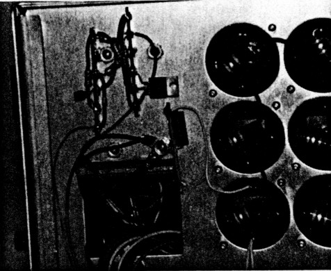
Fig. 6. Terminal strip construction technique used for gridcurrent-derived ALC circuit in MLA-2500.
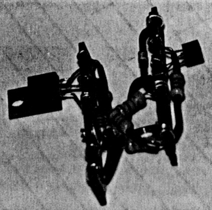
Fig. 7. Final installation of ALC circuit in MLA-2500.
Adapting to other amplifiers
Other tube circuits operating in AB2 can also benefit from the addition of this circuit. 3-500, 813, and 811 users can all probably point to some finite value of grid current in their amplifiers which represents an overdrive condition: for example, my 3CV1500A7 (3CX1000A) begins to distort above 325 mA. The circuit is adapted to other amplifiers by simply choosing a value of grid shunt so that the desired maximum grid current develops 0.6 VDC. The circuit I developed is useful where the grid voltage sample is negative; the E.T.O. circuit could be used where the sample is positive. In either case the addition of a grid-currentderived ALC circuit represents the addition of an extremely useful operating adjunct. By using multiple isolation transistors, as shown in fig. 8, other parameters can be used to limit exciter drive. I have not found such circuits necessary with the 8875s, however. (A more extensive set of construction notes......
WA8AJN, J. Fred Riley.
Part 1 - Part 2