Improving amplifier ALC circuits 2
MLA-2500 input matching and tube protection circuits
The MLA-2500 has acquired a reputation as a tube eater, and it's no secret that the cost of replacing the final tubes in the MLA-2500 has risen from $75 to $520 in just ten years. This has left many MLA-2500 owners nervous about - if not fearful of - tube loss. The ALC and driver matching circuit described in this article should significantly decrease the possibility of tube loss due to overdrive.
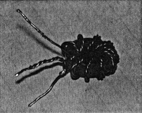
Fig. 1. Toroid input transformer consists of 10 trifilar turns on a T94-2 core.
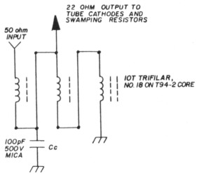
Fig. 2. Toroid internal and external connections show position of compensating capacitor.
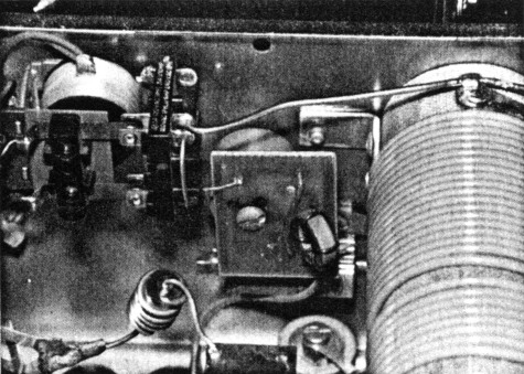
Fig. 3. MLA-2500B input relay area before modification.
One problem that has plagued many MLA-2500 owners is the lack of an input matching circuit. A Kenwood TS-430, for example, is almost unusable with the MLA-2500. The success of the E.T.O. "Alpha" amplifier series has allowed several design ideas to be field-proven. I adapted the broadband, untuned input circuitry used in the small E.T.O. amplifiers to cure the input mismatch problem. The matching circuit is simple to design and construct. Ten trifilar turns of No. 18 enameled wire are wound on a T94-2 core. An electric drill is used to twist three 15-inch lengths of wire together. (The completed coil is shown in figs. 1 and 2. Fig. 3 shows the original input mounting around the input relay in an MLA-2500B. Fig. 4 shows the proper mounting of the input toroid. The wirewound "Non-inductive" swamping resistor used in the MLA-2500 was found to be too reactive to be of use and was removed. I constructed a 50-ohm, 40-watt non-inductive resistor suitable for swamping use from twenty 1-kilohm, 2-watt carbon resistors. I tightly packed the resistors into two groups of 7 and 13 respectively (shown in figs. 5 and 6) and then mounted them as shown in fig. 7. The interconnection is shown schematically in fig. 8.
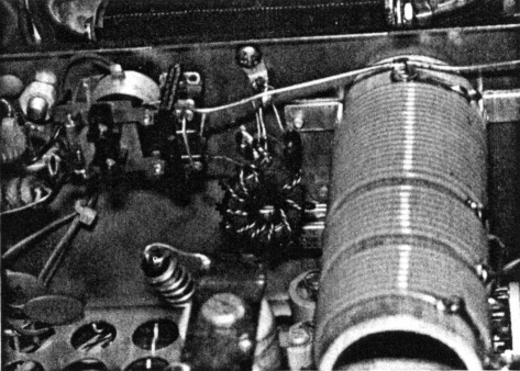
Fig. 4. MLA-2500B input relay area shows toroid connections and mounting to ground lug and relay terminal. Compensating capacitor is visible at top of toroid.
Fig. 5. Construction technique for seven-resistor pack.
Fig. 6. Construction technique used for thirteen-resistor pack.
Fig. 7. Schematic representation of connections from tube cathodes to new swamping resistor packs and remounted cathode choke.
Fig. 8. Installation of resistor packs clearly shown in spaces between tube sockets and wiring harness. Note remounted terminal strip for grid shunt and meter multiplier at top right of photograph.
The next step in stabilizing the input impedance involved moving the cathode RF choke, RFC-4, from the ALC board, PC-1004, to the cathode area. Some older MLAs use an unbypassed RF choke, RFC-7, already installed in series with the cathode line to the ALC board. If no RFC-7 exists, remove RFC-4 from the ALC board and reconnect it between the cathode line common and an empty terminal on the barrier strip mounted between the tube sockets. Install a jumper between the ALC board terminals from which RFC-4 was removed. Move the cathode return line to the barrier strip terminal and add a 0.01 µF bypass capacitor to ground as shown in fig. 8. After installation, the MLA-2500 will present less than a 1.3:1 VSWR to the exciter on all bands from 80 to 10 meters; on 160 meters the VSWR is 1.3:1. Although some variation in the value of the compensating capacitor, Cc, may be required, 100 pF connected as shown in fig. 2 has proven optimum in all retrofits completed to date. The use of different core material and/or core size is likely to necessitate some variation in the value finally selected and the connection terminal.
ALC
The final modification to the MLA-2500 may well be the most important and beneficial to improved performance. The technique employed is a modified version of the circuit used in the E.T.O. Alpha 77. It is a grid-current-derived ALC circuit that uses readily available Radio Shack parts. I could not use the original Alpha 77 circuit because it uses a positive sample voltage whereas negative is used in the MLA-2500. In installing the ALC circuit I also remounted the thermal sensor and increased the voltage to the cooling fan.
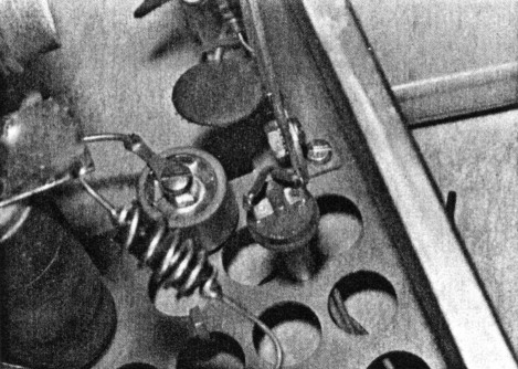
Fig. 9. Original mounting of thermal sensor.
I remounted the thermal sensor, SW-3, shown in fig. 9, from behind the 40-meter loading padder, C42, to behind the 80-meter loading padder, C46. The final position is shown in fig. 10. Why the inside tube should run hotter is not obvious. Nevertheless, the inside tube does run hotter, and moving the thermal switch makes sense. Perhaps the bandswitch disturbs the airflow. You may wish to replace the cooling fan; after extensive evaluation of cooling fans, the Rotron WR2A1 "Whisper" is highly recommended. It is both quiet and efficient. I also removed R20, a 500-ohm, 10-watt resistor, from the thermal sensor circuit. When I removed R20 and rewired around it, I saved the thermal strip and remounted it to the bottom of the chassis below the 40-meter loading capacitor, C42, using C42's mounting screw. This terminal strip is used in the ALC circuit and is shown at the top center of fig. 7. Fifty milliamperes, the new maximum grid current, represents only one-twentieth scale on the original MLA-2500 meter. By replacing the grid shunt, R19, with a 10-ohm, 2-watt resistor and adding a 1-kilohm, 1/4-watt resistor in series with the grid meter line, the full-scale meter reading is increased to 100 mA. As a benefit, enough voltage is available across the new grid shunt to activate the new ALC circuit shown in fig. 5 of part 1. (Fig. 6 of Part One of this article shows the construction technique used and fig. 7 of Part One shows the mounting to the pushbutton mounting nuts.)
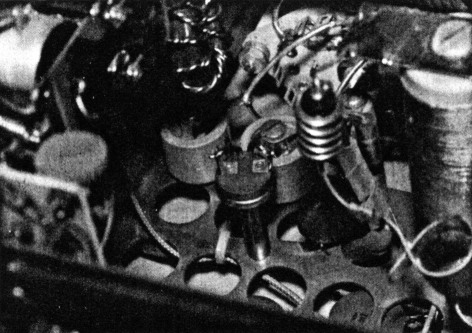
Fig. 10. Remounted thermal sensor positioning.
I used the ground lug on the remounted terminal strip to provide a ground for the new grid shunt, R19, and to provide a terminal point at which to connect the grid meter line to the new series metering resistor, a 1-kilohm, 1 /4-watt resistor. A new wire was added inside the wiring harness from the grid line to the area of the function switch mounting nuts. Using terminal strips modified in Dentron fashion and discrete components I constructed the basic circuit shown before. The - 18 VDC required was obtained by a simple modification to the power supply board, PC-1002. Later model MLA-2500s do not have the 120 VAC winding shown on the schematic. If your unit has a black wire connected to pin No. 3 on the bottom of power supply board, PC-1002, unsolder the wire and tape it back. If your unit has a C32 capacitor installed, remove it. Remove the line going to pin No. 1 bottom - if it exists - and pull it back to the ALC circuit construction area. If no line exists between the ALC and power supply boards, run an additional wire in the harness to connect the ALC board to the new ALC circuit.
On the power supply board, PE-1002, install the new C32 capacitor, observing polarity. Diode CR16 may or may not be present. Use the old CR16 or any general purpose power diode. It may be most convenient to tack solder CR16 in from the 1/T, 2/B (12 VAC) trace on the power supply board to the 1/ B terminal trace to which C32 is soldered, refer to part 1, Fig. 5 for schematic representation. Carefully locate the lines to the transmit light, X-2, and unsolder them from the power supply board. You may wish to use part of the excess wire connecting X-2 to the new ALC circuit for the new line connecting the 1/ B (- 18 VDC) terminal to the ALC circuit. After connecting X-2, the power supply board, and the new ALC circuit, only the ALC board, PC-1004, remains to be modified.
Modifying the ALC board
Remove C22, RFC3 (if present), and R10 from the ALC board, PC-1004. Replace R12 with a 1-kilohm, 1/4-watt resistor. Tack solder the old R12, a 27-kilohm, 1/4-watt resistor, from the input, pin No. 2, trace to ground. Using R10's terminals, correctly remount CR18 in the circuit. This completes the modifications. Check the ALC circuit by insuring that the transmit light, X-2, comes on at 55-60 mA of grid current; -8 VDC should appear at the ALC jack simultaneously with X-2's illumination. The new ALC circuit provides protection from accidental or transient overdrive when connected to the exciter. The input swamping and matching circuit helps limit the maximum grid current available. The increased sensitivity of the grid meter and X-2's visual indication prove powerful tools in preventing accidental or transient overdrive. The ALC circuit should act in concert with the change in cooling to protect the tubes under almost any operating conditions.
"Inadequate warm-up time is something these modifications cannot protect against. Four or five minutes has been found to be a practical minimum. Internal tube arcing can occur even though Eimac's specification sheet calls for sixty second minimum and the MLA provides seventy-five seconds. Increasing the time for warm-up can unquestionably save your tubes."
Acknowledgment
I wish to thank Tom Keadle, W8EII, for the photographs and Rodger Miller, KC8DA, for the use of his amplifier.
WA8AJN, J. Fred Riley.
Part 1 - Part 2