A home brewed six cavity duplexer
Achieve 95 dB of isolation, using inexpensive parts
After building a repeater, I soon realized that I'd need a duplexer in order to use the same antenna for the repeater, transmitter and receiver. After pondering the situation, I decided to build a six-cavity duplexer similar to the one described in the ARRL FM Repeater Manual. This duplexer, while not cheap, still costs much less to build than to buy; the total cost should range from about zero to $250.00, depending on how well your junk box is stocked.
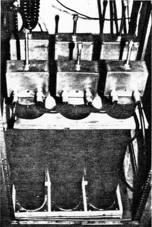
Fig. 1. Six-cavity duplexer with a measured notch of 95 dB and an insertion loss of 1.5 dB.
The duplexer I built has a measured 95 dB of isolation and 1.5 dB insertion loss. Figure 1 shows the completed duplexer in operation on the K9EYY repeater. Figure 2 shows a completed cavity; fig. 2A, a cross-section view (less inductor and capacitor).
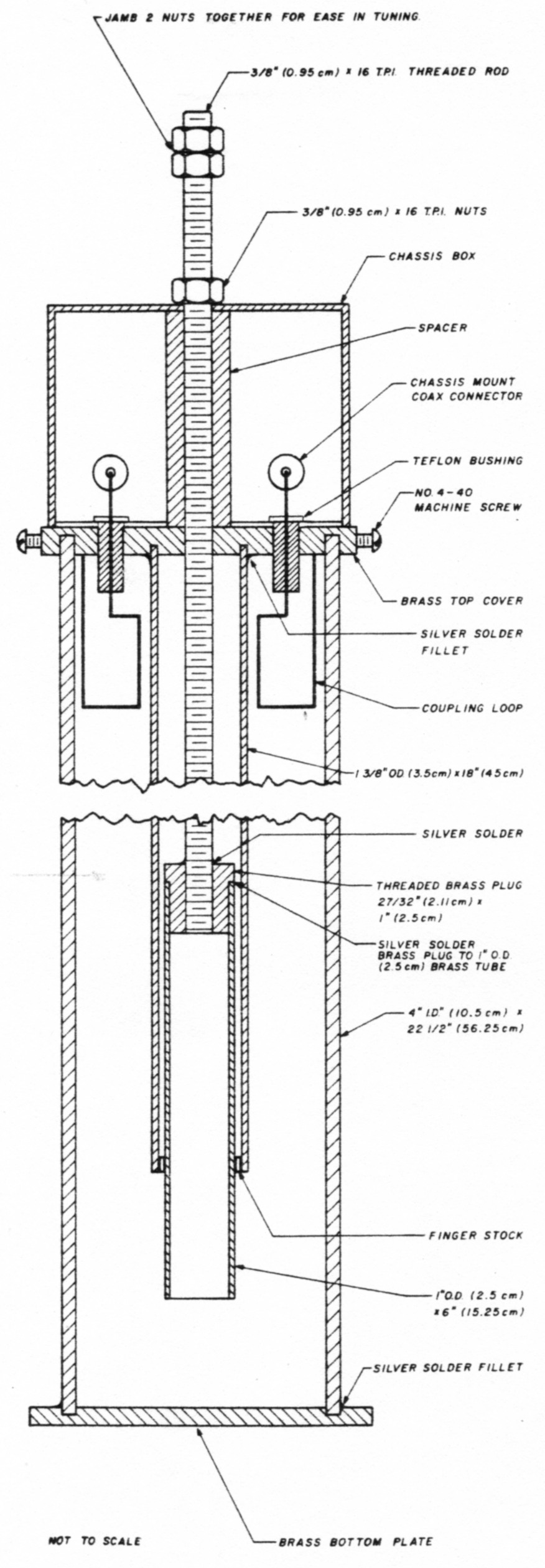
Fig. 2 Completed cavity. Note the locking nut on the threaded rod to hold the tuning adjustment. Also note the metal chassis box, the two "N" type chassis connectors, top and bottom covers.

Fig. 2A. A cross-sectional view of a single cavity. Neither the inductor nor the capacitor is shown in the metal chassis box.
Construction
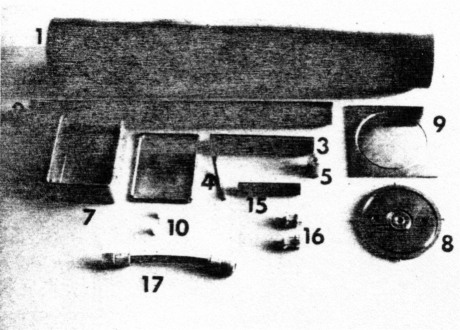
Items to be purchased or fabricated for each cavity. The numbers in the photograph correspond to the numbers in table 1.
| Item number (see photo) | Quantity needed | Description |
|---|---|---|
| 1 | 6 | 4 x 22-1/2 inch (10 x 56.25 cm) copper tubes |
| 2 | 6 | 1-3/8 inch O.D. x 18 inch (3.5 x 45 cm) copper tubes |
| 3 | 6 | 1 inch O.D. x 6 inch (2.5 cm x 15.25 cm) brass tubing |
| 4 | 6 | pieces of finger stock to fit inside item 2 |
| 5 | 6 | tuning plunger bushing - 1 inch (2.5 cm) diameter brass rod |
| 6 | 6 | tuning rods 3/8 inch (0.95 cm) x 16 threaded rod 24 inches (60 cm) long |
| 7 | 6 | boxes to fit on top of cavities |
| 8 | 6 | top covers for 4 inch (10.5 cml tubes made of 1/4 inch (0.6 cm) brass plate |
| 9 | 6 | bottom covers for 4 inch (10.5 cm) tubes made of 1/8 inch (0.3 cm) brass plate |
| 10 | 12 | teflon bushings 1/2 x 1/4 inch (1.35 x 0.6 cm) |
| 11 | 18 | nuts 3/8 inch (0.95 cm) x 16 for tuning rods (6 for locking and 12 for tuning) |
| 12 | 12 | coupling loops (made from No. 16 tinned wire) |
| 13 | 3 | inductors (made from No. 16 tinned wire) |
| 14 | 6 | copper straps 1/4 x 1 inch (0.6 x 2.6 cm) No. 0.020 copper |
| 15 | 6 | 3/8 inch I.D. x height of mini boxes plastic pipe to keep mini box from compressing |
| 16 | 12 | "N" type chassis coax connectors to couple one cavity to another |
| 17 | 4 | 7 inch (17.5 cm) tip to tip RG-192 double-shielded coax to couple the middle cavities to those on each end |
| 18 | 1 | 9 inch (22.5 cm) RG-192 double-shielded coax to couple receive cavities to "T" connector |
| 19 | 1 | 26 inch (65 cm) RG-192 double-shielded coax to couple transmit cavities to "T" connector |
| 20 | 3 | 15 pF small variable capacitor (Johnson 189-5-5) |
| 21 | 2 | lengths of RG-192 to reach from transmitter to transmit cavities and receiver to receive cavities |
The first step in construction is to cut the 4-inch (10-cm) copper pipes to a length of 22.5 inches (56.25 cm). If you are using the thin wall variety of copper pipe, handle it carefully to avoid distortion. Square both ends of all six pieces by using a lathe and a steady rest to support your work.
Next cut the 1-3/8 inch (3.44 cm) copper pipes to a length of 18 inches (45 cm). Once again you should square both ends of all six pieces. Cut the 1-inch (2.5-cm) O.D. brass tubing to 6-inch (15-cm) lengths. You will need six of these. Now machine 6 brass plugs from 1-inch (2.5-cm) brass rod stock as shown in fig. 3. The center hole in each brass plug is threaded with a 3/8 inch (0.938 cm) x 16 tpi tap.
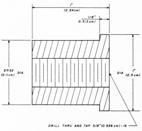
Fig. 3. The dimensions of the six threaded brass plugs made from 1 inch (2.5 cm) brass rod.
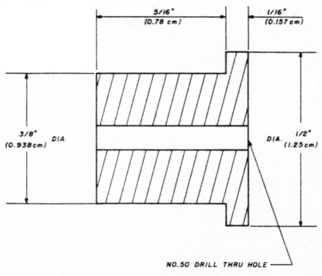
Fig. 4. The dimensions of the 12 teflon bushings that allow the coupling loops to pass from the cavities through the top covers and into the chassis boxes. Note the No. 50 drill hole through the center of each bushing.
The teflon insulating bushings are fabricated next. (Refer to fig. 4.) Use very sharp cutting tools in the lathe tool holder and rotate the teflon material slowly in the lathe. I used a speed of approximately 35 RPM (I used the back gearing on the lathe) and it cut very easily. You will need two of these bushings for each cavity, for a total of 12 teflon bushings. Be sure to drill a No. 50 hole in each bushing for a No. 16 wire.
Use the lathe to fabricate an aluminum plug (see fig. 5A) to be used when silver soldering the threaded rod, the brass plug, and the brass tube. Then fabricate another special aluminum plug to the dimensions shown in fig. 5B. This plug will be used to temporarily hold the finger stock inside the 1-3/8 inch (3.5-cm) copper tube while you silver solder the finger stock in place. This plug will prevent the "fingers" from getting too hot and losing their temper. The solder will not adhere to the aluminum.
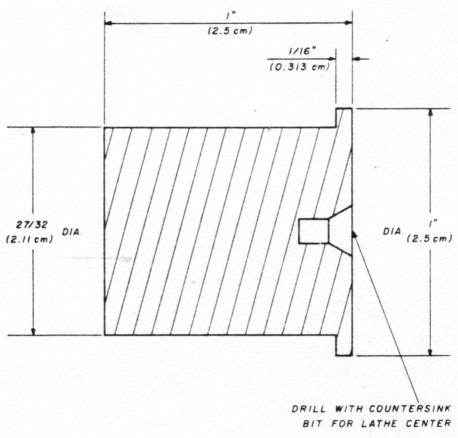
Fig. 5A. The dimensions of the single aluminum plug used to fit into the open end of the 1-inch (2.5-cm) tube and supports the open end in the lathe center while the threaded rod, the brass plug detailed in fig. 3, and the brass tube are silver soldered.
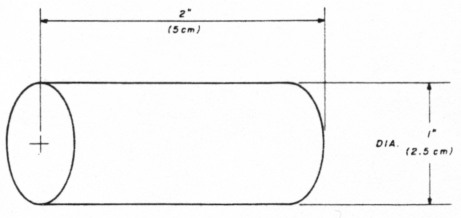
Fig. 5B. The dimensions of another aluminum plug to be used when silver soldering the finger stock inside the six 1-3/8-inch (3.44-cm) copper tubes.
Thread a nut onto a piece of 3/8 inch (0.938 cm) x 16 threaded rod. Run the nut past the point where you will cut the rod, then cut the rod to a length of 24 inches (60 cm). Then run the nut off the cut end of the threaded rod to chase or clean any threads which may have been damaged when you cut the rod to length. You will need six of these rods (one for each cavity).
Now look at fig. 6. Notice that a plastic pipe is slid over the threaded rod and fitted snugly inside the metal box. Check the inside measurement of the metal boxes you will be using and cut six lengths of this 3/8-inch (0.938-cm) I.D. plastic pipe to fit snugly inside the box. This spacer is used to keep the box from changing its shape when you tighten the lock nut after you have adjusted the cavity.
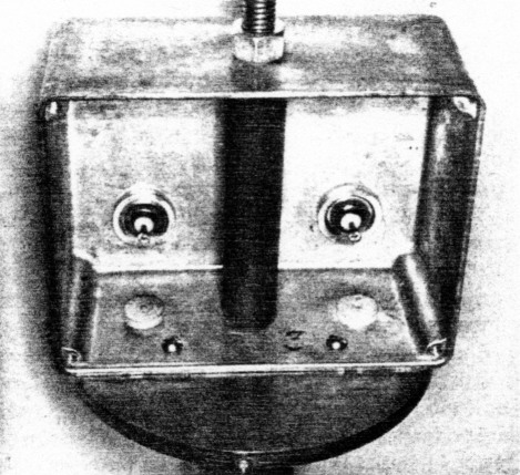
Fig. 6. Detail of plastic pipe spacer, threaded rod, locking nut, teflon bushings, coax fittings and how they fit in the box.
See fig. 7A. Make six bottom covers for the six 4-inch (10-cm) tubes by cutting square pieces of 1/8-inch (0.313-cm) brass plate so that they measure 4-1/2 x 4-1/2 inches (11.25 x 11.25 cm). Chuck these pieces of brass in the lathe one at a time and cut a 4-inch (10-cm) slot 1/16 inch (0.175 cm) deep, so that the 4-inch (10-cm) tubing fits snugly into the 1/16 inch (0.175 cm) circle you cut into each 1/8 x 4-1/2 inch (0.313 x 11.25 cm) square piece of brass base. You should have approximately 1/4 inch (0.625 cm) between the circle and the outside edge of these pieces of brass.

Fig. 7A. One of the six bottom covers showing the slot. The large copper pipe will fit in this slot and be silver soldered to the plate.
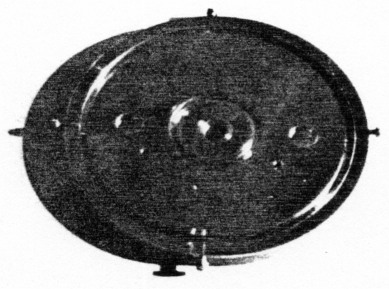
Fig. 7B. A completed top cover. Note the center threaded hole, the two holes for the teflon bushings the two slots for the copper tubes, the 6-32 threaded holes and the four 4-40 bolts in their holes.
Refer to figs. 7A and fig. 7B. Fabricate six top covers to fit on the 4-inch (10-cm) copper tubes, using 1 /4-inch (0.625-cm) brass plate stock. Cut rough 5-inch (12.5-cm) circles from the brass plate stock with a hacksaw. Then insert the rough sawed blank into your lathe chuck. (A 4-jaw chuck might be easier to use at this point.) Cut this blank to 4-1 /2 inches (11.25 cm) in diameter and drill a 5/16 inch (0.78 cm) hole in the exact center of this cover plate. Thread this hole with a 3/8 inch (0.94 cm) 16 tap. Cut a circular slot 4 inches (10 cm) in diameter and 0.150 inch (0.375 cm) deep. The width of the slot should equal the thickness of the large 4 inch (10 cm) copper pipe, and the slot large enough so that the cover will fit snugly on the top end of the large copper pipe. Cut another round slot 1-3 /8 inch (3.5 cm) in diameter and 1/8 inch (0.31 cm) deep to accommodate snugly the 1-3/8 inch (3.5 cm) 0.D. copper pipe. Drill 2 holes 3/8 inch (0.94 cm) in diameter exactly 2-5/8 inches (6.56 cm) apart. The centers of these two holes should be exactly 1-5/16 inch (3.28 cm) from the center of the hole you drilled and threaded. These holes will accommodate the teflon bushings.
Refer to fig. 7B and notice the four small screws pointing inward toward the center of the cover. These are used to hold the brass covers on the top of the large copper pipes. Use a No. 43 drill and cutting oil to drill 4 holes as close to the bottom of the cover plate as you can. Tap these holes with a 4-40 tap. (Use a good grade of cutting oil or you will break the tap every time. The broken taps cannot be removed and the exposed edges must be ground off.) Fit 4-40 bolts in each of the tapped holes. If you grind a small point on the end of these bolts, they will hold the cover on the pipe more securely.
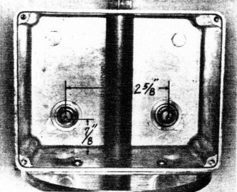
Fig. 8. One of the six chassis boxes. These boxes are held to the top cover plates with the two 632 bolts in the foreground. Also note the spacer inside the box, the "N" type coax chassis mounts and the teflon bushings.
Refer again to fig. 6 and also to fig. 8. Try to select a cast mini-box rather than a box made by bending sheet aluminum. The cast box will be more rigid and will keep the cavity tuned. Each box will include:
- input and output coax connectors (chassis mount) located 7/8 inch (2.19 cm) up from the bottom of the box, 1-15/16 inch (3.28 cm) from the center of the box.
- a 7/16 inch (1.09 cm) hole through the top and bottom of the box.
- two 3/8 inch (0.940 cm) holes for mounting the teflon bushings; they must align with the holes in the top cover plate.
- two holes for fastening the box to the top plate of each cavity (6-32 bolts).
- a spacer installed between the top and bottom sides of the box to keep the box from distorting when tuning is completed and the lock nut is tightened. This spacer can be metal or plastic. The inside diameter should allow the 3/8 inch (0.94 cm) threaded rod to slide inside the spacer.
The boxes I used measured approximately 4-3/4 inches (11.88 cm) wide, 3-1/2 inches (8.75 cm) high and 2-1/4 inches (5.63 cm) deep and were obtained at a surplus outlet.
Assembly
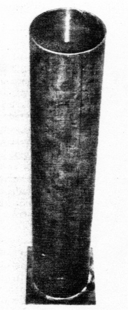
Fig. 9. One of the six main copper tubes silver soldered to the bottom cover plate.
Figure 9 shows the main 4-inch (10-cm) diameter copper tube silver-soldered to the brass bottom plate. (Using low-temperature silver solder, we were able to attach the 4 inch (10 cm) tubes to their bases with the heat from only one acetylene torch in spite of the great conductivity of the 4 inch, 10 cm, copper tube.) Place the tube in the slot you machined in each square brass plate, apply flux, and silver solder the base plate to the 4 inch (10 cm) copper tube. Check for trueness before you lay the piece aside.
Next place the 1-3/8 x 18 inch (3.44 x 45 cm) copper tube into the slot previously cut in the round 1/4 inch (0.63 cm) brass top plate. Check for trueness and silver solder in place. See fig. 10 which shows the tube silver-soldered to the brass top cover plate. It also shows how the finger stock fits inside the other end of this tube. The finger stock should be silver soldered to the inside of 1-3/8 inch (3.44 cm) tubing at the lower end. Figure 10 shows its location and how it must contact the 1-inch (2.5-cm) tube for adjustment purposes. When silver soldering the finger stock, do not overheat the fingers. The aluminum plug you made earlier will help prevent overheating. I used a propane torch and the low temperature silver solder mentioned above. Obviously, you will not have the 1 inch (2.5 cm) brass tubing inside the finger stock while silver soldering. Instead, use the aluminum plug to hold the finger stock securely inside the 1-3/8 inch (3.44 cm) copper tube while you are soldering. After soldering, slide the 1-inch (2.5-cm) brass tube inside the finger stock. If the finger stock does not make firm contact with the 1-inch (2.5-cm) tube, remove the 1-inch (2.5-cm) tube and bend each finger inward so that it does make firm contact.
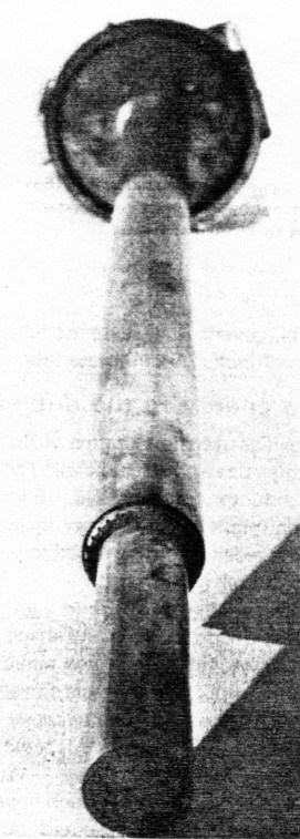
Fig. 10. The top plate silver soldered to one end of the 1-3/8 inch (3.44 cm) O.D. copper tube and the finger stock silver soldered to the other end (foreground) Note how the finger stock firmly contacts the inner tube.
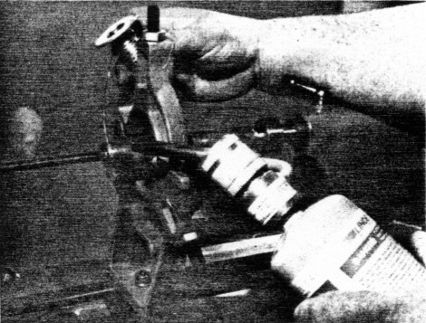
Fig. 11. This is how the threaded brass plug is silver soldered to the brass tube and threaded rod while turning in the lathe. Note how the aluminum plug described in fig. 5A is used to support the other end of the brass tube in the tail stock live center rest.
Examine fig. 11 for the following details. It is very important that the 1-inch (2.5-cm) brass tube be attached to the 24-inch (60-cm) length of 3/8 inch (0.938 cm) by 16 threaded rod as accurately as possible. In other words, when the 3/8 inch (0.938 cm) by 16 (adjustment) threaded rod is turned, the 1-inch (2.5-cm) brass tubing should not wobble in the finger stock inside the 1-3/8 inch (3.44 cm) copper tubing. An easy way to accomplish this is to put one end of the threaded rod in the lathe chuck and thread the other end into the brass plug you machined earlier. Slide the 1-inch (2.5-cm) brass tube onto this plug. Then put the small aluminum plug (see fig. 5A) in the open (other) end of the 1-inch (2.5-cm) brass tube. Support this end by having the live center (or dead center) ride in the countersunk hole drilled in the center of this plug. The other end of the brass tube is held "centered" by supporting it in the steady rest. Lubricate the steady rest jaws and rotate the entire assembly while silver soldering the threaded rod into the threaded brass plug, and the plug to the brass tubing. When the silver soldering is complete, continue to let the piece rotate until it has cooled. Figure 11 shows the threaded brass plug, the threaded rod, the aluminum plug, and the 1-inch (2.5-cm) brass tube as well as the steady rest as it was set up in my case.
After the assembly cools, thread the rod up through (0.625 x 2.5 cm). Refer to fig. 14 and cut six pieces of copper flashing. Then connect them to the 15 pF the brass top covers. Make sure the finger stock firmly contacts the 1-inch (2.5-cm) brass tube. (See fig. 10.)
Coupling energy to the duplexer
Three cavities use short lengths of No. 16 wire while the other three use a small capacitor. The three cavities that have inductors made of No. 16 wire connected from the input to the output coax chassis connectors will go to the receiver and be tuned to provide a notch at the transmitter frequency.
Refer to figs. 12 and 13. Bend a length of No. 16 tinned wire to the dimensions and shape shown in fig. 12. Temporarily connect all three inductors between the input and output coax chassis connectors. Do not solder these wires at this time because you will have to remove them for the first step in the tune-up procedure later.
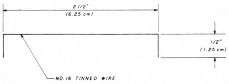
Fig. 12. The dimensions and shape of the inductor, which spans the input and output coax chassis connectors inside three of the chassis boxes.
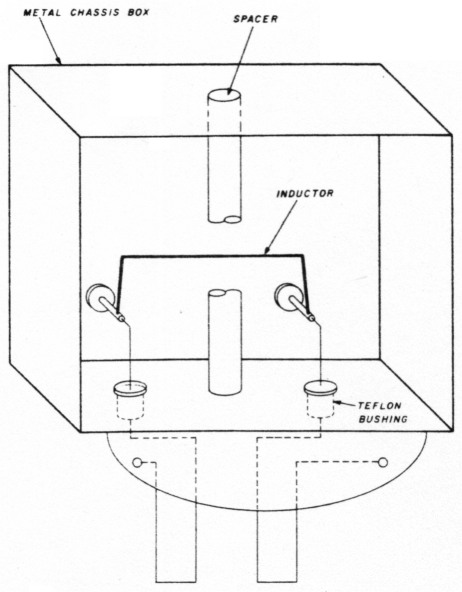
Fig. 13. The inductor is connected in three of the cavities.
The other three cavities will each have a small variable capacitor (15 pF) connected between them. These three can then be put in the transmitter line and the notch tuned to the receiver frequency. The capacitors are connected to the input and output coax connectors with copper strips measuring 1/4 x 1 inch capacitors as shown in fig. 15 and fig. 18. Solder these three capacitors to the copper strips (see figs. 15 and 18), but do not solder to the input and output connectors yet.
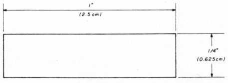
Fig. 14. The dimensions of one of the two copper straps that attach to each 15 pF capacitor. Make six of these.
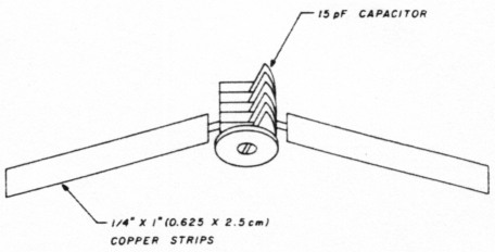
Fig. 15. 15 pF capacitors are connected with two copper straps in each of three cavities.
The loops that couple the energy into each cavity are also made of No. 16 tinned wire. Their shape and dimensions are critical: use figs. 16, 17, 18, and 19 for the proper configuration and measurements. Connect these loops to each input and output connector and to the bottom side of the top plates. Do not solder the wires yet. Hold the copper strips in place and solder the wire coupling loops and simply tack solder the copper strips to the input and output connectors (fig. 18).
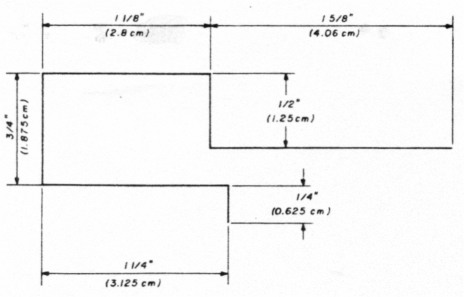
Fig. 16. Two of these loops are usd to couple the signal into and out of each cavity. Make 12 out of No. 16 tinned wire. (These measurements are critical, as is the shape of the loops.)
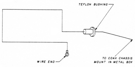
Fig. 17. This diagram shows how the wire end is fastened to one end of the loop and how a teflon bushing fits on the wire.
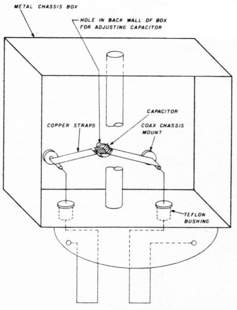
Fig. 18 Location of capacitor, copper straps, and coax connectors. Note hole in back wall of box for tuning the capacitor.
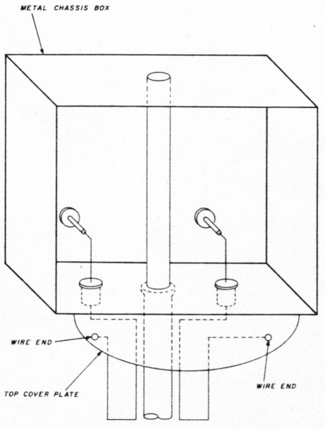
Fig. 19. The loops fit on the top covers, pass through the teflon bushings and on to the coax chassis fittings.
One end of these loops is tied to the underside of the top plates. I modified some small wire ends and tapped 4-40 holes. The 4-40 screws through the wire. ends provide a mechanically secure and electrically good anchor to the underside of the top plates. (See fig. 16, 17, 18, and 19.) The coax chassis mounts are located 5-5/8 inches (6.56 cm) apart, (or 1-5/16 inches, 3.28 cm, on each side of center) 7/8 inches (2.19 cm) up from the bottom of the mini-box.
Building the wooden holder
After all six cavities have been built, mount them together in a holder and tune them to the desired frequencies. (Refer to figs. 20, 21, and 22 for construction of the wooden holder clamp assembly.)
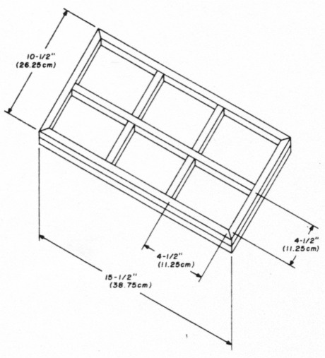
Fig. 20. Wooden base holds all six cavities. The base covers fit into the square pockets.
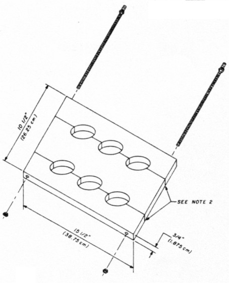
Fig. 21. The details of the upper clamp.
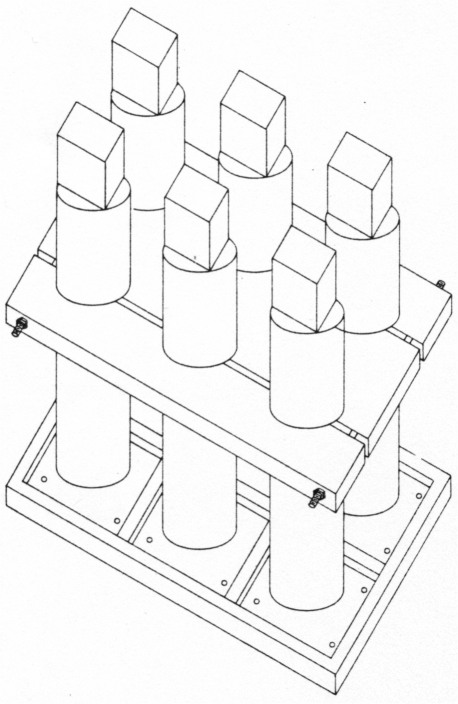
Fig. 22. Overview of the wood cavity supporting device.
The cavities should not be allowed to touch each other as this will tend to detune them. You can build a special holder to prevent them from contacting each other, by following these steps:
- Cut a piece of plywood 1/2 inch (1.25 cm) or 3/4 inch (1.875 cm) 10-1/2 x 15-1/2 inches (26.25 x 38.75 cm). Cut 1/2 x 1/2 inch (1.25 x 1.25 cm) wood strips and screw and glue them to the plywood base so that six squares measuring 4-1/2 x 4-1 /2 inches (11.25 x 11.25 cm) are formed. This is the base.
- Cut a piece of 3/4 inch (1.875 cm) plywood to 10-1/2 x 15-1/2 inches (26.25x 38.75 cm). Place six marks on one side of this plywood. The six marks should align with the exact center of the six square compartments in the base piece. Using these six marks as the centers of six circles, use a compass to draw 4-inch (10-cm) circles around each of these six points. (See fig. 21.)
- Mark two straight lines through both groups of three circles. Saw along these lines. You will have three pieces of plywood, each with one-half of three 4-inch (10-cm) circles drawn on the pieces. Using a band-saw, cut out the 4-inch (10-cm) circle halves. Then drill a hole through the ends of the three pieces of plywood to accommodate a 1 /4-inch (0.625-cm) threaded rod. This becomes the upper support. (See fig. 21.)
- Place a cavity in each base compartment and put at least two wood screws through the brass plate base and into the wood base. Place the upper support around the six cavities and tighten the nuts on the threaded rod.
Alignment
We will align the cavities in two stages: stage one for rough tuning each of the six cavities, and stage two for fine tuning the cavities and connecting them all together.
Note that the 3/8-inch (0.94-cm) x 16 threaded rod is for PASSBAND tuning. The capacitor, in the case of the transmitting cavities, adjusts the NOTCH. (In the case of the receiving cavities, the inductor adjusts the notch.)
In these examples, 147.825 MHz will be used as the repeater transmit frequency and 147.225 MHz as the repeater receive frequency. We will adjust the three transmit cavities to pass 146.825 MHz and notch the 147.225 MHz frequencies. The three receive cavities will be tuned to pass 147.225 MHz and notch 147.825 MHz.
Stage one: rough tuning
Remove the inductors and capacitors from all cavities. Remove all interconnecting coax cables. (See fig. 23.) Connect an RF signal generator (amplitude-modulated for convenience) to one of the cavities (fig. 26). If your signal generator outntc is 50 ohms, you will not need to use a 3-dB patl ti the output is not 50 ohms or if it is suspect, the', connect a 3-dB pad between the signal generator ai'-j t e cavity. See fig. 24 if you do not have a 3 dB pad.
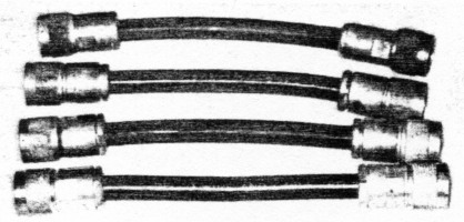
Fig. 23. Four cables connect the two middle cavities to the outside ones. Made of double shielded coax, they measure exactly 7 inches 117.5 cm) from tip to tip.
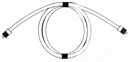
Fig. 24. If you do not have access 43 s 3-dB pad, you can use this device which will be suitable for tuning the cavities. Use RG-58 coax and coil up a 50 to 75 foot (15 to 22.5 meters) length into a neat coil; put connectors on each end. Tape the coil neatly.
Next connect a 50-ohm detector between the other cavity terminal and an oscilloscope. If you do not have a 50-ohm detector, you can construct one as shown in fig. 25.
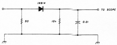
Fig. 25. Schematic diagram of a 50Ω detector suitable for use in this tuneup application. These components should be put in an RF-tight box or enclosure.
For the three transmit cavities (the ones which will have the capacitors connected later), adjust the signal generator to within ± 100 kHz of 147.825 MHz (fig. 26). Then adjust the center threaded rod (passband) until the scope shows maximum energy transfer. You will need to reduce the level of the signal generator as well as the scope gain as tuning progresses.
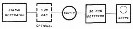
Fig. 26. These are the cunnections `or the initial tuning of the six cavities. If you don't have a 3-dB pad, see fig. 24.
Adjust all three cavities. From this point on, leave the threaded rods alone. Connect the variable capacitors across the input and output connectors of all three transmit cavities.
Connect the signal generator through a 3-dB pad to one of the transmit cavities - now roughly adjusted - then through another 3-dB pad to an FM transceiver which has an "S" meter as shown in fig. 27. (If you do not have a 3-dB pad, refer to fig. 24.) Adjust the signal generator (CW mode) to exactly 147.225 MHz and an S6 reading on the receiver, which is also tuned to 147.225 MHz. Adjust the capacitor (which you just connected in the cavity) for the lowest S-meter reading possible. You may have to increase the output of the signal generator to maintain a visible S-meter indication. When you have obtained the lowest S-meter reading - i.e., the deepest notch - go on to the next cavity.
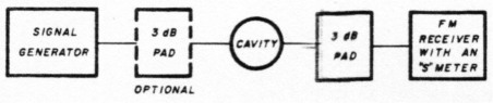
Fig. 27. These are the connections to use when setting the notches in the three transmit cavetiess by adjusting the 15-pF capacitors, and the inductor when adjusting the three receive cavities.
After all three transmit cavities have been adjusted, go back to the beginning of this section and perform the same steps for the three receive cavities. Note that you will now be dealing with the inductors you made from the No. 16 tinned wire instead of the capacitors. Adjust the No. 16 wire inductors to deepen the notch. Remember that the frequency to be passed is now 147.225 MHz and the notch frequency is 147.825 MHz.
The inductor dimensions given should be all right, but if the notch is not good enough, try using larger or smaller wire, or even a copper strap if necessary.
Stage two: fine tuning
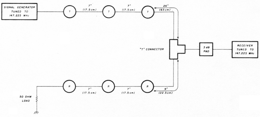
Fig. 28. These connections are made for the final adjustment of the duplexer transmit cavities.
Connect cavities according to fig. 28. Tweek the center-threaded rods on the transmit cavities only for minimum signal at the receiver (maximum notch). These adjustments interact somewhat. Keep increasing the signal generator output as the S-meter reading decreases. Reconnect according to fig. 29. Tweek the center threaded rods on the RECEIVE cavities only for minimum signal (maximum notch). Repeat these steps several times. You may be amazed (as I was) to see the notch get deeper and deeper with each repetition of these steps. You will also notice that bringing objects into the near vicinity tends to detune the cavities slightly as you approach the - 100 dB point.
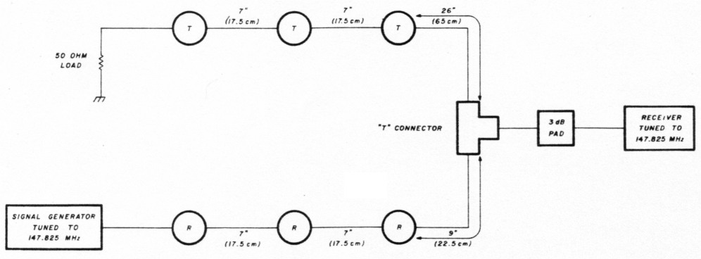
Fig. 29. These connections are made for the final adjustments of the duplexer receive cavities.
Lock the threaded rods by tightening a 3/8 inch (0.94 cm) x 16 nut against the mini-box as you finish the last adjustment on each cavity.
Acknowledgements
Naturally when one becomes involved in a project of this magnitude, friends often prove helpful. In this regard, I would especially like to thank Ted Gisske, K9IMM, and Chuck Forster, WA9ACI, for their technical help over many months, and Mel Seamans, WB9PKH, for helping with coax when my budget was really strained. I would also like to thank Jim Osborn and Sherm Fusch for their photographic efforts and advice. Joe Androfski, K9OMF, provided constant encouragement, and hands-on help over many hours during the construction and tune-up phases.
Obtaining the parts
Because some of the materials needed are rather unusual, they may not be available at your local hardware store. Others will have to be machined.
The two most unusual items are the pieces of 4-inch (10-cm) diameter copper drain pipe and the brass plate. The copper pipe can often be found at a large plumbing wholesale supply house, often buried under some other pipe. Try looking under "Brass" in the business section of any large city telephone book; you may find the names of outlets for brass plate listed there. If the ones you call don't stock it, ask for the names of other companies. I found my brass plate through just such a referral. I had to drive about 200 miles, but I got it from Howard Brass and Copper in Milwaukee. (Ask for "tag ends" - they're cheaper.)
Finger stock can be constructed, but the commercial material is much better. I got mine (Stock No. 134B) from Tech-Etch Inc., 45 Aldrin Road, Plymouth, Massachusetts 02360.
The best choice of solder for this project is silver solder with a low melting point - i.e., 400 degrees (204 degrees centigrade). Ordinary silver solder, with its higher melting point, is more difficult to work with, and regular hard solder will cause problems if you should decide to silver-plate your project later (see "Safe, Sensible Silverplating," page 29). Silver plate will adhere to silver solder, but is likely to flake off of hard solder. My 1/16-inch (0.16-cm) diameter silver solder (manufactured by the J.W. Harris Co., Inc., 10930 Deerfield Road, Cincinnati, Ohio 45242) came from a local rock shop. Do purchase paste or liquid flux to use with your silver solder.
The 3/8-inch (0.94-cm) x 16 threaded steel rod can be obtained at almost any large hardware store.
The teflon can be found in some hardware stores or plastic stores. I got mine from a friend in the paper business. When large piles of paper stock are cut, a guillotine type of cutter is used. The blade comes to rest against a square piece of telfon. From time to time the teflon is rotated to expose a new unused surface. After the four sides have been used, the strip is replaced with a new one. The used strip has plenty of stock left to make the feed-through bushings.
The No. 16 tinned wire is a standard item available at hardware stores and ham swapfests. The small copper strap can be made from a piece of copper flashing. Get a scrap from a roofer or builder. All 12 "N" type chassis mounts and connectors were purchased at flea markets or swapfests. RG-192 coax can be found at dealers or hamfests, as can Tee connectors.
K9EYY, J.S. Gurske.