Designing a station for the microwave bands 1
Easing your way into a new frontier
In many respects, the microwave bands represent a frontier for Amateurs; above the more familiar regions of VHF and UHF, they're often thought of as a magic domain. Like any physical frontier, they hold promise of untapped possibilities along with seemingly insurmountable barriers. Fascinating in attraction, they hold out hope for open space as the lower bands become full and, ultimately, overcrowded.
Although the microwave bands are often considered useful only for short range contacts where both stations are within line of sight of each other, microwave DX contacts are possible, often over paths which are anything but visual. One of the first surprises I encountered on 10 GHz was being able to clearly copy a 10-milliwatt transmitter by means of scatter off a mountain visible to both receiver and transmitter. The mountain was about 6 miles from both stations, and the direct path was blocked by another mountain. Antennas were a 4-foot dish on one end and a palm-sized horn on the other. Try that on VHF or below with similar sized antennas and equivalent power!
Such contacts aren't limited to scatter from mountains. Microwave communications over extremely long distances are possible via tropospheric and marine ducting even when lower frequencies are not. The current 10-GHz world's record of over 1000 miles bears testimony to this. Commercial jetliners offer a large enough (scattering) cross section to be usable for beyond-the-horizon contacts. Even more generally useful, the same tropospheric scattering that provides over-the-horizon communication at VHF is in effect at microwave frequencies. Moonbounce echoes with only a few tenths of a watt of transmitter power have recently been reported at 10 GHz.
At least part of the secret of these seemingly impossible modes of propagation lies in the high antenna gains available with physically smaller, and therefore realizable, antennas. Virtually all of the available transmitter power may be focused into a pencil-like beam. This can provide more signal to a distant receive antenna than would be possible with antennas of the same size at lower frequencies. This may mean, for example, that it would require 100 watts at 144 MHz to provide the same received signal level in 4-foot antennas that 0.1 watt can provide on 10 GHz!
Another part of the secret is narrowband operation. In the past, most Amateur microwave operation was accomplished with free-running, unstable oscillators. This method required wide receiver bandwidths to accommodate the transmitted signal. In addition, the receive local oscillator was often the same one used on transmit, which further increased the necessary bandwidth. While this approach was simple, signal to-noise ratios were degraded by the additional noise present in the wider bandwidths. Reducing communications bandwidth from, say, 300 kHz to 3 kHz provides the same improvement in signal-to-noise ratio as increasing transmitter power from 1 watt to 100 watts - i.e., 20 dB.
Admittedly, 'there are difficulties in building and operating an Amateur station in the microwave bands, but the excitement of these new regions and the chance for new records and discoveries certainly should draw some of us to further exploration.
As one goes higher in frequency, the number of components that provide gain and power is limited. In addition, maintaining stable and accurate frequencies as well as pointing high-gain antennas accurately are problems to be overcome. The point-to-point nature of microwave DX tends to reduce the likelihood of random contacts. "Round table" QSOs with many stations in different locations may require innovations in Amateur networking, but progress in these areas is currently being made at lower frequencies as digital Amateur radio progresses. The store-and-forward bulletin boards and network nodes currently being used in Amateur packet radio are steps toward a more complete information handling structure. Increased traffic over these channels requires higher data rates and more bandwidth becomes necessary. As our channels support higher information rates, digitized voice and other linear modes can be used. The available spectrum and point-to-point nature of microwave DX links make them ideal for such operation. As Amateur packet radio becomes increasingly popular, implementation of high-speed microwave "backbones" for long-distance cross-country communication becomes an attractive possibility.
Design approach
This article describes one approach to designing and implementing a station for the Amateur microwave bands (as well as the two highest UHF bands, 1296 and 2304 MHz). The intent is to promote interest and show how to build a station that can provide all-mode contacts over significant distances. CW, SSB, and NBFM are obvious initial choices, but digital and video modes can be used as well, since the entire system supports linear signal frequency translation.
This open-ended approach minimizes complexity by taking advantage of readily available components and equipment. The intent is simply to demonstrate a practical way for more Amateurs to get on the microwave bands.
The bulk of this series focuses on generation of stable and precise local oscillator signals, since this is a primary hurdle that must be crossed for any narrow-band operation at microwave frequencies. The local oscillator, a mixer, and an antenna are the minimum requirements for converting low-frequency Amateur transmitters and receivers for microwave operation.
Real communications over significant distances are indeed possible with this minimal station. The basic station doesn't have to be expensive. Receive preamplifiers and transmit amplifiers may be added at very little cost, and the recent availability of low-noise amplifiers in the 4-GHz range makes a good low-noise, moderate-power (by microwave standards) station actually affordable. QSOs over hundreds of miles are possible with such equipment and just a small, reasonably priced dish antenna. For less than the cost of a 2-meter fm transceiver, one may assemble a station capable of providing microwave DX and the excitement of participating in the exploration of still-uncharted regions of the radio spectrum. A block diagram for generating microwave SSB is shown in fig. 1.
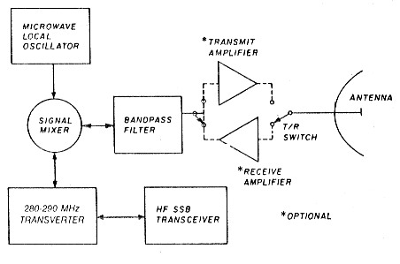
Fig. 1 - Microwave SSB is generated by converting a 20-30 MHz SSB transceiver first to 280-290 MHz and then to the microwave band using a microwave LO and mixer. A microwave bandpass filter removes unwanted mixing products.
A secondary goal of this article is to demonstrate a way to put a high-performance station on the microwave bands with as little test equipment as possible. Wherever possible, rf technology replaces complex microwave hardware. I've tried to use commonly available parts wherever possible, and kept the number of pc boards to a minimum by the use of common circuits. Only two microwave circuits, the mixer and PLL downconverter, have to be built, since the oscillator - a GunnplexerTM, for example - can be obtained commercially or as surplus (look for motion detectors and automatic door openers). Except for these, the entire station is assembled from standard VHF or lower frequency components and circuits.
I'd encourage anyone interested in getting on the microwave bands to seek out other interested Amateurs. Small users groups can be a great help in getting started and maintaining enthusiasm. They're also a good way to share not only measurement equipment, but expertise.
Local oscillator
As shown in fig. 1, the basic blocks for a microwave station are the signal mixer, a bandpass filter to remove unwanted mixing products, and the microwave local oscillator. Transmit and receive amplifiers are optional. Of these blocks, the local oscillator is probably the most complex. The problem of generating a stable local oscillator in the microwave bands may be solved in more than one way. Certainly an obvious method is to adopt the same techniques used at lower frequencies and traditional in Amateur VHF and UHF construction. That is, one may simply start with a high quality quartz oscillator - perhaps in the 100-MHz vicinity, since crystal oscillators there can have good spectral purity - and multiply up to the final microwave frequency selected. One problem with this is the necessity of including an active device and filter in each harmonic stage. If too high a harmonic number is used, it may be difficult to separate the preferred harmonic from the undesired ones around it. Even if suitably high Q filters are available, the extra complexity and amplifier power necessary to generate sufficient energy to operate a mixer is undesirable. This approach also isn't very versatile, since modifying oscillator fundamental frequencies, not to mention a whole string of harmonic filters, makes significant QSY extremely difficult. In addition, signal levels and multiplier stage gains need to be controlled to avoid multiplying broadband noise and degrading the ultimate microwave signals.
One alternative to frequency multiplication is to directly phase lock a microwave oscillator with a phase-locked loop (PLL). This is particularly interesting because when pushing any active device to its upper frequency limit, an oscillator may be built even when frequency multipliers and amplifiers aren't possible. A phase-locked oscillator may be used to produce a signal at frequencies where few active devices are available. Since suitable oscillators are readily available both commercially and on surplus markets, phase lock is an attractive possibility for Amateur operation that requires a minimum of microwave equipment construction.
Normally, to phase lock an oscillator, a signal that's a sample of the oscillator is compared to a high-stability reference signal. A loop amplifier is then used to steer, or "lock" the oscillator in step with the reference signal. A block diagram for phase locking an oscillator is shown in fig. 2A. The "phase sample" may be the oscillator signal itself, a frequency-divided or a frequency-converted version of it, as long as phase information is retained. Using the oscillator signal it-, self would require that the reference signal already be the desired stable signal. Using a divided signal would require dividers that operate at the oscillator frequency, but microwave frequency dividers aren't yet Amateur junk box items!
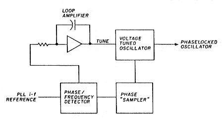
Fig. 2A - A simple phaselocked loop (PLL) holds a voltage tuned oscillator IVTO) in constant phase relationship to a reference signal. A signal which is a representative "sample" of the VTO's phase must be provided.
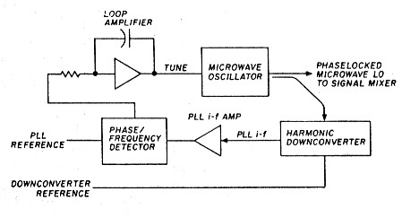
Fig. 2B - Phaselocked microwave source block diagram.
In its simplest form, frequency conversion presentsthe same disadvantage as using the oscillator signal directly - a precise microwave signal must already be available. However, it's possible to use a harmonic mixer to downconvert the oscillator signal (see fig. 2B). Such a mixer mixes the oscillator signal with a harmonic of a much lower frequency reference. This lower frequency reference signal may itself be produced by PLL techniques.
If phase lock is achieved by harmonic downconversion, the phase comparison may be accomplished at low i-f frequencies where gain is easy to come by and measurements are far easier to perform. Additionally, the harmonic converter need not have particularly low conversion loss, since only a reasonable signal-to-noise ratio is sufficient, the absolute signal level can easily be modified with i-f amplifiers. This is in contrast to harmonic multiplication, which requires enough drive at each stage to drive the active device or mixer into its nonlinear region. Step-recovery diode multipliers often need several hundred milliwatts of drive to function properly. Harmonic downconverters may need only 10 to 50 milliwatts of lower frequency drive, a much easier proposition. Additionally, phase-locked oscillators don't usually require filtering to remove unwanted signals as do multiplied oscillators, as long as the reference frequency components are suitably reduced by the loop filter.
Any available microwave oscillator may be used as long as a means of electronic tuning that will allow correcting the frequency over a range which is larger than the drift caused by mechanical and environmental factors can be found. Many Gunn diode oscillators may be tuned by slight adjustments to their power supply voltage. Other oscillators, such as the Gunnplexers made by M/A-Corn, have an electronic tuning input. The PLL bandwidth must also be sufficiently high to clean up the oscillators' instabilities acceptably. It must be possible to modulate the microwave oscillator at frequencies a few times higher than this loop bandwidth for good loop stability. The bandwidth is easily adjusted by changing the PLL loop parameters, and usually something in the tens of kHz area is adequate. Because any local oscillator must be stable and accurate, the PLL is automaticlly a suitable choice in this respect. If all oscillators in a system can be referenced to one precision (preferably ovenized) reference oscillator, the best in frequency stability and accuracy may be obtained.
Table 1. Combinations of a few basic reference signals allow great flexibility in generating phaselocked microwave signals. Combinations using a 1010 MHz reference allow access to every amateur microwave band, using either a 280-290 MHz or a 420-440 MHz SSB if.
Reference signals
| Ref osc | Freq = (harm x ref) + PLL if |
|---|---|
| 10std | Quartz standard in proportional oven |
| 100ref | 100ref = 10 x 10 std +0 (decade divider instead of i-f) |
| 150ref | 3 x (100ref / 2) |
| 20ref | 100ref / 5 |
| 30ref | 3 x 10std |
| 10ref | 20ref / 2 |
| 40ref | 20ref x 2 |
| 8ref | 40ref / 5 |
| 330ref | (3 x 100ref) + 30ref |
| 990ref | (10 x 100ref) - 1Oref or 3 x 330ref |
| 992ref | (10 x 100ref) 8ref |
| 1008ref | (10 x 100ref) + 8ref |
| 1010ref | (10 x 100ref) + 10ref |
Microwave Local Oscillators
| Band | 1st LO = (harm x ref) + PLL if | SSB if | hf SSB dial (260 MHz 2nd LO) |
|---|---|---|---|
| 1296 | 1008 = 1008ref directly | 288 MHz | 28 MHz |
| 1010 = 1010ref directly | 286 MHz | 26 MHz | |
| 2304 H* | 2016 = 2 x 1008ref | 288 MHz | 28 MHz |
| 2304 H | 2020 = 2 x 10¹⁰ref | 284 MHz | 24 MHz |
| L | 2020 = 20 x 100ref + 20ref | 284 MHz | 24 MHz |
| 3456 H | 3030 = 3 x 10¹⁰ref | 426 MHz | |
| L | 3020 = 30 x 100ref + 20ref | 436 MHz | 436 MHz SSB |
| L | 3020 = 3 x 10¹⁰ref - 10ref | 436 MHz | 436 MHz SSB |
| 5760 H | 6048 = 6 x 1008ref | 288 MHz | 28 MHz |
| 5760 H | 6060 = 6 x 10¹⁰ref | 300 MHz | |
| L | 6020 = 60 x 100ref + 20ref | 280 MHz | 20 MHz |
| L | 6020 = 6 x 10¹⁰ref - 40ref | 280 MHz | 20 MHz |
| 10368 H | 10080 = 10 x 1008ref | 288 MHz | 28 MHz |
| 10368 L | 10080 = 10 x 1010ref6 - 20ref | 288 MHz | 28 MHz |
| 24192 H | 23760 = 24 x 990ref | 432 MHz | 432 MHz SSB |
| 24192 L | 23760 = 24 x 992ref - 48 | 432 MHz | 432 MHz SSB |
| 24192 L | 23910 = 24 x 990ref - 150ref | 282 MHz | 22 MHz |
| L | 23910 = 24 x 1010ref - 330ref | 282 MHz | 22 MHz |
Common oscillator circuits
After many years of VHF and UHF construction, there are two kinds of circuits I've gotten tired of building: one is power supplies (especially those with tubes) and the other is local oscillator/ multiplier strings. Although using a PLL can simplify local oscillator construction, there are several microwave bands, and it's best to avoid duplication of circuits as much as possible. To simplify multiband stations, many microwave enthusiasts are adopting a scheme using a 288-MHz SSB/CW i-f and local oscillators derived from a 1008-MHz precision source. All of the Amateur microwave bands except 24 GHz may be reached by mixing either 288 MHz or 432 MHz with a harmonic of 1008 MHz and selecting the appropriate sideband.
I've chosen a modification of this approach that uses 1010 MHz and a 280- to 290-MHz VHF intermediate frequency. Allowing slight deviation of the signal i-f from 288 MHz can also allow the MHz digit on the hf signal source to indicate correctly. For example, for operation on 2304 MHz, the hf transceiver is tuned to 24 MHz, giving an i-f of 284 MHz. This signal mixed with two times 1010 MHz gives 2304 MHz, and the MHz digit of the hf rig displays the MHz of the output frequency correctly. Since many of the newer transceivers will operate in transverter mode over 20 to 30 MHz, this approach seems to be suitable.
Table 1 shows some alternatives for generating signals on the microwave calling frequencies using this phase-locking approach. The reference signals are all derivatives of the 10-MHz standard oscillator. Phase lock is obtained by mixing a harmonic of a reference signal with the local oscillator to produce a PLL i-f frequency. This PLL i-f is then locked to a reference signal, producing a phase-locked local oscillator signal which can then be used to convert the 280- to 290-MHz VHF i-f to and from the preferred microwave band. The VHF i-f is generated using a 260-MHz phase-locked LO and the 20- to 30-MHz range of the SSB transceiver.
Also shown are some more traditional multiplying approaches for achieving a microwave LO.
Notice that the 1010-MHz phase-locked approaches all provide correct readout of the MHz digit of the SSB source. This may be of little concern for operation on only one microwave band, but since one LO system can effectively put you on all the microwave bands, frequency confusion in the heat of a contest may be something to reckon with!
The additional flexibility of the PLL i-f also provides access to the 24-GHz band. If this band seems esoteric, I'd like to point out that a 24-GHz oscillator with a built-in mixer diode is available for approximately $50. It may be possible to phase lock and mix for the receive i-f all in one diode, eliminating any other microwave hardware! Similar oscillator/mixer modules, designed for radar "gun" use, are available for 10 GHz.
Preparing the 10-GHz station
The approach just described, which can be used either directly or with some modifications to get on all of the Amateur bands - affords a great deal of commonality in phase-lock circuitry. It's possible to lay out one circuit board that can be configured for almost every variation required for any of the locked loops. (This is important to avoid the power supply syndrome mentioned above!) Standard ECL integrated circuits and commonly available operational amplifiers are all that's required except for the harmonic downconverters. Adding another microwave band generally requires only an oscillator, a harmonic downconverter, and an additional phase-lock pc board. Also, significant frequency change within a band is often accomplished by simply selecting a different reference signal and changing the coarse frequency adjustment of the microwave oscillator.
In all cases, from 10 MHz to microwave, the best "raw" oscillator should be used. At 10 MHz, the longterm stability of the standard is the desired characteristic. The loop bandwidth of this PLL is kept low so that the poorer phase noise contributions of the 10-MHz standard won't contaminate the less accurate but cleaner 100-MHz quartz oscillator. At 1010 MHz, the operating Q of the resonator and the resulting oscillator spectral purity is kept as high as possible. This oscillator is really rather stable when unlocked. Measurements over a period of several days and at a relatively constant temperature showed only a few tens of kHz drift. The spectrum of this oscillator when locked is essentially a replica of the tenth harmonic of the 100-MHz crystal oscillator. This feature, combined with simplicity of construction, makes this an effective solution to the problem of generating a clean and stable GHz signal.
A multiplier/filter string could be used to generate this 1010-MHz signal instead of the direct phase-locked approach. This would probably require either an ovenized 101-MHz oscillator or dividing by 101 and phase locking to a 1-MHz reference derived from a master station oscillator. In that case, sufficient filtering at 1010 MHz must be provided to reduce spurious signals to -70 dBc or less. The direct phase-lock approach provides a clean spectrum that's directly attributable to the high-Q resonator, as long as loop bandwidth is small enough to keep reference frequency sidebands sufficiently low. The only other spurious signals present are multiples of the 100-MHz signal from the harmonic downconverter. These signals, predominantly the odd harmonics at 900 MHz and 1100 MHz, are attenuated by the isolation between the 1010-MHz buffer amplifiers.
The microwave oscillator may be whatever you can get or build. However, using Gunn diode oscillators (such bs the M/A-Com Gunnplexers) results in a 10.080-GHz signal that has as clean a spectrum as many hf transceivers on 20 meters. The resulting 10,368-MHz SSB signal is also of excellent quality.
Gunn diode oscillators used as sources for automatic door openers have been tried with similar results. Using this LO approach on 10 GHz is quite amazing. Even when out on a hilltop, once the oven for the 10-MHz frequency standard is operating at temperature, the hf transceiver can be set exactly to a scheduled frequency. When the another station calls, the SSB signal from a similarly phase-locked distant station is tuned correctly. A detailed system block diagram is shown in fig. 3.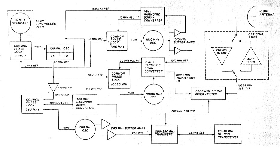
Fig. 3 - A precise 10,368 MHz SSB station can be made from only 5 oscillators and 4 nearly identical phaselock circuits. The PLL downconverters are similar in topology and easy to construct.
Order of construction
For those planning to build an entire 10-GHz station, construction of the 100-MHz oscillator and ECL dividers is a good place to start. If a 10-MHz standard is available, the phase-lock circuit may be built and the 100-MHz oscillator phase locked. If possible, a common pc board should be made and several boards loaded and tested. Then, building the 1010-MHz oscillator, buffer amplifers, and downconverter, and changing four components on one of the pretested phase-lock boards, will result in a precision 1010-MHz reference signal. Next, building the 260-MHz oscillator and locking it with another of the phase-lock boards and adding mixers and amplifiers produces the 280- to 290-MHz i-f transverter. At this point, both 1296 and 2304 are within easy reach by adding just a mixer (and amplifiers, if you wish). For 2304, an antiparallel diode mixer just like the harmonic downconverters will suffice to get a signal on the band without even building a doubler or additional locked 2020-MHz oscillator. Inexpensive MMIC amplifier blocks can be used for transmit and receive amplifiers to produce a respectable 1296- or 2304-MHz station almost immediately. Finally, the 10,080-MHz LO is obtained by locking a Gunn oscillator with one more common pc board and the 10-GHz harmonic downconverter. Here again, one can immediately get on the band at the few hundred microwatt level by just adding the signal mixer. This mixer can even be built on the same TeflonTM pc board and at the same time as the harmonic downconverter. A simple bandpass filter for 10,368 MHz has already been discussed, and a two-stage amplifier will be described at the end of this article.
For those who want to get on the 10-GHz band as rapidly as possible, the flexibility of this phase-locked approach offers many choices. It is possible, for example, to get on 10,368 MHz SSB using only a 148-MHz SSB signal as the i-f. This can be done by generating a 1020-MHz signal instead of 1010 MHz fok4 the microwave downconverter reference, simply by using a 20-MHz reference in that PLL and coarse tuning the resonator 10 MHz higher. Also, using a 20-MHz reference on the 10-GHz Gunn oscillator PLL gives 10 x 1020 MHz + 20 MHz = 10,220 MHz. 10,220 MHz LO + 148 MHz SSB = 10,368 MHz SSB. The10,220-MHz LO could also be used with a 30-MHz wideband i-f to work other Amateurs in the area not yet on narrowband modes using 10,220/10,250 full duplex. SSB operation could be utilized by just changing to the 148-MHz SSB i-f. Notice also that reversing the reference and VCO inputs to the phase comparator allows locking on "the other side." In this last example, 10,180 MHz would result from such a reversal. Many combinations of reference frequencies and tuning directions are possible, and this versatility is an attractive aspect of this whole approach.
Common phase-lock circuit
By taking a uniform approach to local oscillator generation, that of phase locking to a relatively low frequency reference, a great deal of commonality in circuit design is achieved. In fact, all four phase-lock loops used to generate 10,368-MHz SSB have identical phase detector, loop amplifier, and lock indicator schematics. Only the loop filter component values need to be varied to accommodate the differing oscillator characteristics. This is a great boon to construction, since one circuit board may be laid out which serves all four loops. The phase-lock circuit board uses ECL line receivers to amplify the reference and VCO inputs, phase detection is in a 12040-ECL phase comparator, and standard operational amplifiers are used in the loop amplifier/filter and phase-lock detect circuits. A schematic of the common phase-lock circuit is shown in fig. 4.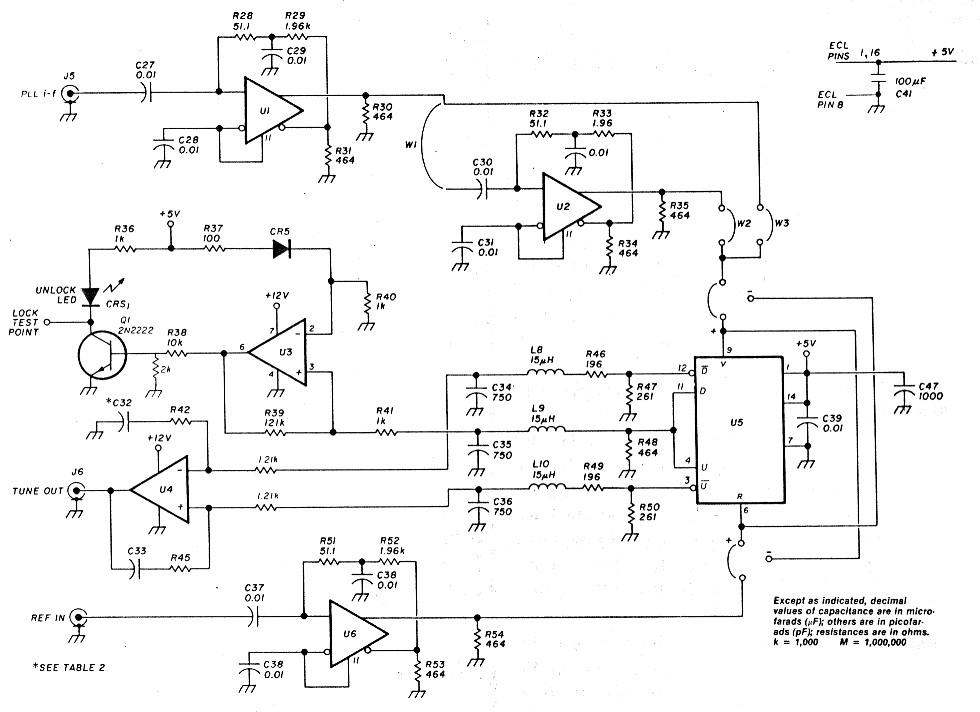
Fig. 4 - The common phaselock circuit uses inexpensive ECL and op-amp integrated circuits. Only 4 components and 2 jumpers need be changed for a great variety of different applications.
I made a common pc board that contained the phase-lock circuits, the 100-MHz oscillator and dividers, and the 1-GHz harmonic downconverter/PLL i-f amplifier. All this fits on a double-sided 3- x 6-inch board, and only the parts required for a particular function need be added. Normal VHF construction practices are followed, including good bypassing on the ECL logic, which is important since operation is from + 5 instead of - 5 volt supplies. The only circuit that operates higher than 100 MHz is the anti-parallel diode mixer, and the two diodes can be mounted right next to a coax connector to keep lead length to near zero.
I chose to use a large number of small coaxial connectors between circuits. This is more expensive, but it adds a great deal of versatility in changing reference frequencies, measuring signal levels, and so forth. For VFO control, any of the PLL reference frequencies may be substituted with a variable frequency reference as long as ECL logic levels are provided. This may be useful in testing or experimenting. Substituting the 10-MHzfeterence on the 1010-MHz PLL oscillator with a 10- to 11-MHz variable oscillator, for example, could give a variable 10,080- to 10,090-MHz microwave signal with the same stability as the tenth harmonic of the variable oscillator. This might be useful as a signal source for microwave testing.
The PLL characteristics are modified by changing R42/R45 and C32/C33. This is necessary to provide different loop bandwidths and accommodate different oscillator tuning sensitivities. Table 2 gives some values for some selected bandwidths and oscillators. For situations not listed, approximate values may be calculated. Referring to fig. 5:

Fig. 5 - The loop amplifier (integrator) controls the characteristics of the PLL. Loop parameters are set by properly selecting component values. In this balanced configuration, each component appears twice.
![]()
Where A(s) = loop gain at frequency s
Kd = phase detector sensitivity in volts/radian
Ka = loop integrator gain at s
Kv = oscillator sensitivity in radians/(volt sec)
N = frequency division of oscillator before phase detector
Component values can be calculated by first selecting a loop bandwidth and setting Ka to give unity gain at that frequency:
![]()
Where ωn = loop bandwidth in radians/sec (radians/sec = 2πf with f in Hz)
![]()
Next C can be selected by choosing 1/(R2 × C) to be four or five times lower in frequency than the loop bandwidth to provide adequate loop stability.
![]()
As an example, let's assume we want to lock an oscillator with a tuning sensitivity:
![]()
![]()
Since we have no frequency division (a harmonic mixer is a mixer, not a divider), N =1.
Suppose we want a 50-kHz loop bandwidth to "clean up" the oscillator. Then:
![]()
![]()
and
![]()
It is important for loop stability that both the oscillator and the op amp operate well below their roll-off frequency. For the oscillator, its tuning sensitivity should be constant to at least five times the loop bandwidth selected. In the case of the op amp, the product Kawn should be no more than 10 to 20 percent of the specified gain-bandwidth. This specification will depend on the particular op amp used, but if wn is always selected to keep Kawn below 1M radians/second, performance should be satisfactory. When in doubt about loop stability, design for a lower loop bandwidth; noise sidebands on the oscillator may be higher, but at least the loop will be stable!
100-MHz oscillator and divider circuits
A clean 100-MHz quartz oscillator is locked to a stable, though less spectrally pure, 10-MHz standard oscillator. In the event that a stable 10-MHz standard is not available, this oscillator may be operated unlocked, but the frequency accuracy and drift may not be as good as you would like for SSB and CW weak-signal operation, particularly on the higher bands. In any case, this 100-MHz reference may be built first and used for locking the higher frequency oscillators even without a 10-MHz standard.
Table 2. Typical loop amplifier component values for phaselocking the 10 GHz station oscillators. Other oscillator sensitivities can be accommodated by calculating values as demonstrated in the text.
| Oscillator | 100 MHz VCXO | 1010 MHz | 10,080 MHz Gunn Osc | 260 MHz 2nd LO |
|---|---|---|---|---|
| Loop bandwidth | ||||
| f (Hz) | 50 | 50k | 50k | 50k |
| Wn (rad/sec) | 310 | 310k | 310k | 310k |
| VTO sensitivity, Kv | ||||
| MHz/volt | 0.0002 | 0.5 | 3 | 1 |
| rad/(volt sect | 1300 | 3.1M | 19M | 6.3M |
| Loop Gain, Ka | 18 | 0.77 | 0.13 | 0.38 |
| Divide if N | 10 | 1 | 1 | 1 |
| R42/45 (ohms) | 25 | 1.1 | 180 | 530 |
| C32/33 (µF) | 0.6 | 0.015 | 0.09 | 0.03 |
These values assume R43/44 = 1210 ohms and R46/49 = 196 ohms and phase detector-sensitivity, Kd = 0.13 volts/radian.
A two-stage Pierce harmonic circuit is used with a UHF TV tuner varactor diode to allow frequency control. A variable capacitor may be substituted when no 10-MHz standard is used. An ECL line receiver is used to level shift and buffer this oscillator and drive the bi-quinary ECL divider. The divider output drives one input on the common phase-lock circuit (if used), the other input being provided by the 10-MHz standard oscillator. The loop parameters are set to give 10 to 100 Hz of loop bandwidth. The divide-by-five output of the 10138 divider provides a 20-MHz reference signal for use in the other loops. The 10-MHz ECL signal is also brought out. The schematic of this circuit is shown in fig. 6.
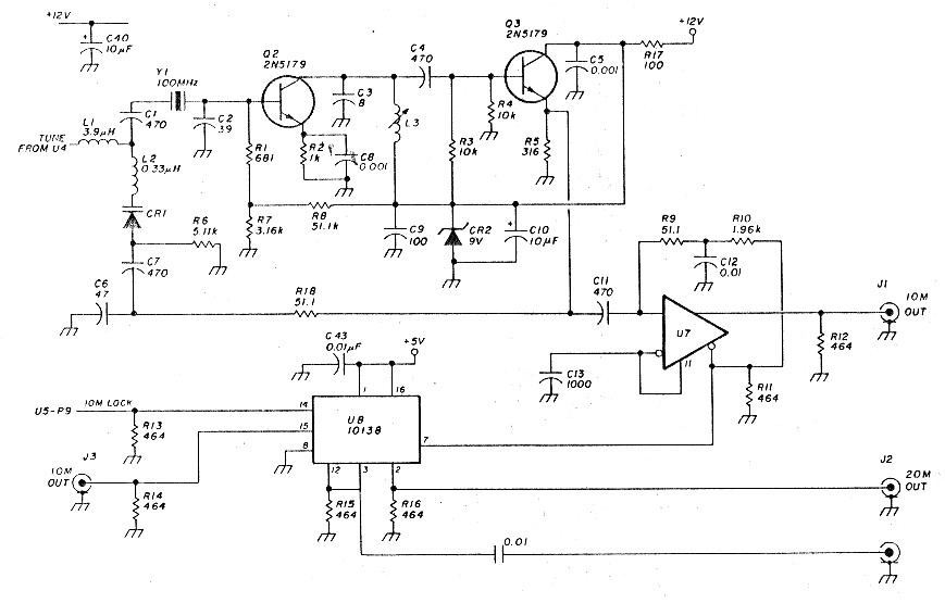
Fig. 6 - The 100 MHz crystal oscillator and divider circuits provide reference signals for generating all higher frequency signals. The oscillator itself can be locked to a precision 10 MHz frequency standard.
Beyond following the usual sound VHF practices, no special precautions need be taken in constructing this circuit. Whether or not 10-MHz standard is being used, it's a good idea to position components so that the entire oscillator circuit can be shielded and, if possible, thermally insulated to avoid frequency drift from ambient temperature change.
Testing
If an oscilloscope, spectrum analyzer, or 100-MHz frequency counter isn't available, both the oscillator and divider circuits should be built at the same time. Then a 10-MHz WWV receiver or any receiver that tunes 10 MHz may be used to ascertain oscillation and division. Before trying to "close the loop" and lock the 100-MHz crystal oscillator, it's a good idea to check that the tuning range is from approximately 1 kHz below 100 MHz to 1 kHz above. This can be done by applying both 5-volt and 12-volt supplies and listening to the divider output at 10 MHz to see that the signal swings 100 Hz on either side of 10 MHz when a 2- to 10-volt tuning voltage is applied. Next, hook up the loop amplifier and the 10-MHz reference signal (from any source that is within this tuning range) and monitor the tuning voltage. If the loop locks correctly, the unlocked LED should extinguish and the tuning voltage should move between ground and the positive 12 volts as L3 is adjusted. At each end of that range, the unlocked light should light, indicating unlock due to an out-of-range 100-MHz oscillator. If a problem exists, make sure that the phase comparator inputs are correct, the connections marked "+" are being used, and recheck for wiring errors.
The second installment will cover construction of the 1010-MHz oscillator, harmonic downconverters for both 1 and 10 GHz and some circuits for biasing and driving the 10-GHz Gunn oscillators.
Reference
- Glenn Elmore, N6GN, "A Simple and Effective Filter for the 10-GHz Band," QEX, Volume 65, July 1987, page 3.
Part 1 - Part 2 - Part 3
N6GN, Glenn Elmore.