A Practical Antenna Electrometer
static, and the interest in this often sometimes useful natural occurrence, we're re-publishing Tony Hopwood's original article. Please see the special panel (at the end of the rep article information from Albert Heyes G3ZHE, who built and used his own vesion of the Electrometer Editor.
The innovative Practical Antenna Electrometer project, designed and built by Tony Hopwood, featured in this article - was originally published in the November 1988 issue of PW. Its reappearance is directly due to the interest in, and increasing problems of atmospheric static! Static is a fact of life for radio enthusiasts. Not only does the ,qcrackle of a storm background fizz and blanket DX reception, it can a so become a real hazard when an antenna takes a kilo-volt charge from a passing thunder-storm or unusual atmospheric conditions. A well insulated wire antenna is an efficient collector of the atmospheric electric charge and monitoring that charge gives a fascinating and accurate insight into present and future local weather conditions.
Because the atmospheric may overload when the antenna takes a charge of more than a few volts. A practical antenna electrometer must have a high input impedance and be able to follow an input that can swing hundreds of volts positive or negative with respect to earth. It must also read accurately and be immune to damaging transients from nearby lightning strikes. A single triode valve operated in cathode-follower mode, hung between stabilised positive and negative h.t. (high tension) rails will do all this. This it does along with providing a self-calibrating impedance. However, any indirectly heated, top cap grid triode or triode strapped pentode would service.
Transformer T1 has two secondary windings, a 250V which supplies the h.t. and a 6.3V used to power the heater of V1. Two silicon diodes D1 and D2 are connected as half wave rectifiers across the h.t. winding of T1, providing both positive and negative rails. Two gas-filled stabilisers, V2 and V3 (VR150/30) are fed from the two half wave rectifier networks, D1/C4 and D2/C3, providing 150V positive and negative supply rails. A electrical field has a fair weathered source impedance of over 10 TΩ (a Teraohm is 1012 Ohms) it can only be monitored by a high input impedance device. However, it's easy to build a portable and sensitive low voltage electrometer using mosfets, but unless a stable GΩ input bias resistor is used, the instrument will only show relative field measurements and read-out of most atmospheric conditions.
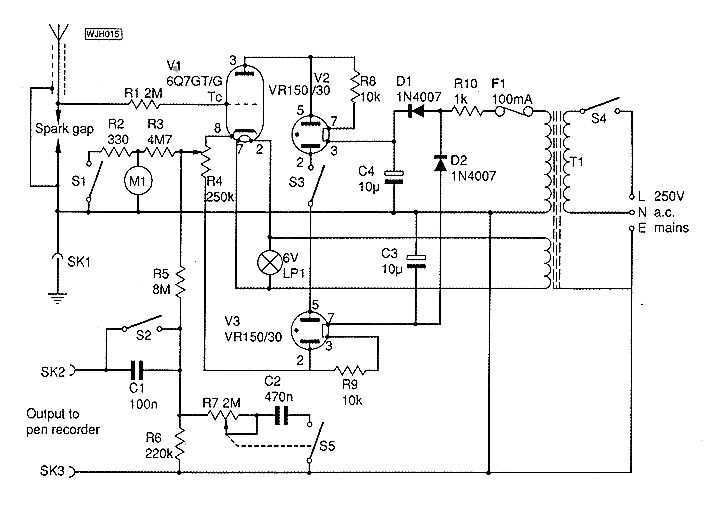
Fig. 1: Circuit of the 1988 Electrometer project by Tony Hopwood.
Simple Circuit
The circuit shown in Fig. 1, is very simple and uses three valves, one triode and two stabiliser tubes. My choice of valve was a 6Q7GT type, mainly because it is still available new*, plus it has a top cap grid connection making it easy to maintain a high input stabilised supply is not essential, but does improve the small signal sensitivity and accuracy. Other power supply arrangements could be tried if a surplus transformer is to hand, such as the type that can be salvaged from an old valved radio. These generally have a 300-0-300V h.t. winding plus one or two heater windings. This higher h.t. voltage is permissible ... provided the heater cathode insulation of the valve used is adequate and the heater circuit is left floating.
A 300-0-300V supply is about the maximum that most ordinary valves and bases will take without the risk of insulation failure. In addition, with more than 600V across the valve, the small signal background noise level will rise due to the supply variations and the internal leakage of the valve.
*See note regarding valves and components in the information panel at the end of the article. Editor.
Cathode Load
The valve is wired with a cathode load resistor chosen to set the current at full positive input of 1-2mA. The cathode voltage, and hence the antenna charge, is read by a centre-zero microammeter arranged as a volt-meter, scaled to suit the power supply voltage.
I used a 250kΩ potentiometer as the cathode resistor so that zero could be set with the grid of V1 earthed. Switch S1 is used to select the 200V range resistor, R3, by disconnecting the 20V range shunt resistor R2.
Switch S3 is included to give the instrurnent the option of an extra high voltage range. Another worthwhile refinement was to provide an output attermator giving a 5V peak to peak signal for driving a pen recorder. The attenuator also includes an additional variable CR damping or integrating circuit for trace averaging, as well as a switched series capacitor to give an a.c. output signal for lightning transient recording.
Bread Board Construction
Both the instruments made by the PW staff, and my prototype were constructed using the old bread boarding technique. There are two good reasons for this, the first being that the design, as it stands, might be termed as a semi-experimental instrument.
Additionally, the shape and form of the instrument will depend on each individual's requirements and component sources. The second reason for the rather exposed layout is partly due to the sensitivity of the instrument being disturbed by earth loops. This means that the use of a metal case is rather difficult and the use of a plastic or a wooden case is not available, due to their potential risk.
Good Quality Components
Good quality new components for use in valved equipment are rather difficult to come by, particularly high voltage working electrolytic capacitors. However, there is plenty of leeway, within reasonable limits, on most of the values of capacitors and even resistors, but the component working voltages must be adhered to. A good source of these components may be your local radio and TV repair shop, they do still exist!
The centre-zero meter used in the PW prototype is not as sensitive as that used in the author's original, the choice being limited by availability and price of components. The 50-0-50µA originally used, often went full scale, so it shows there's some room for improvement.
The values of resistance shown will support most moving coil meters up to 250µA f.s.d. If, after a period of use with a less sensitive meter it seems the usable scale is rather small, try experimenting with the values o R3 and R4.
When the read-out is by moving coil meter and servo-pen recorder with a sharp frequency cut-off above 10Hz, the induced 50Hz mains wave riding on the antenna is integrated to zero and ignored, although it may be many volts peak-to-peak. This 'invisible' waveform will cause problems if the output is measured by d.v.m. or any instrument using switched sampling. It will have to be removed by additional signal conditioning, particularly if the electrometer output is to be recorded on a computer.
Ideal Characteristics
A cathode follower valve has ideal characteristics for electrical field monitoring. Although the normal 'fair weather' field potential is some +100V/m from earth, the source impedance is so high that a 15m long antenna 8m above ground gives a cathode follower d.c. output signal of less than 10V positive, from a true ionic potential of nearly 1W.
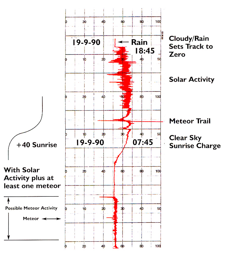
The inherent signal compression is useful, as the study of electric field is more concerned with change rather than actual potential. However, the equipment is still sensitive enough to pernrit the recording of small field changes as well as the more dramatic events associated with convective cloud building, thunderstorms and solar flares.
Although an ordinary well-insulated wire antenna works well in dry weather, sensitivity falls dramatically when it gets wet. This is no bad thing in thunderstorms, but if true allweather insulation is wanted, then additional insulators designed to preserve a dry surface must be used.
One simple method is to provide a rain hood made from either plastic drain pipe with the insulator secured with resin spread up inside the tube. Alternatively, you could use the top half of a washing-up liquid bottle to shield the insulator, as in Fig. 2.
Lastly, experience showed that the readings were less prone to variations caused by bodily movement near the instrument, if the antenna was brought into the shack via good quality coaxial cable (UR67).
High Voltage Spikes
Although the valve will tolerate high voltage lightning spikes, the antenna can still take a charge of several W, so some precautions are advisable. It's a moot point whether it is safer to earth an antenna during a storm, or to fit a spark gap to earth it where the system enters the building.
Note. On the PW, a small stand-off insulator was not available to terminate the antenna to R1, so a new, but surplus, petrol engine spark plug was used. It was mounted on the base board by a Rrry clip bolted to a right angle bracket. If the spark plug's outer metal case it earthed through the clip, it will serve not only as a cheap stand-off insulator, but also double as a spark gap. Editor. (1988 comment).
Lightning tends to strike the highest earthed object, and earthing the antenna may turn it into a more attractive target than nearby trees, power lines or TV antennas! If lightning does strike, anything connected to outdoor wiring is at risk, no matter how remotely connected, including radios, TVs and telephones. Even if it appears to be a relatively poor path to earth, it will be at risk.
Remember, the most likely outcome of a lightning strike is fire. Fortunately, this type of thing doesn't happen all that often, but be sure to keep clear of the antenna when the sparks start to fly! As a further point of safety, it may be wise not to rely just on the mains to earth to ground the 0V line of the instrument. A second local earth should be provided if possible, by some stout wire and an earthing spike driven into moist ground.
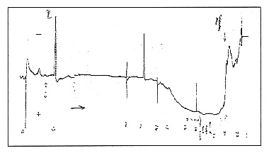
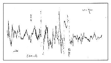
The fact is, if you shut down the station while the storm is overhead, you will not miss much, because the field variations will be way beyond the range of the instrument. (I find the most interesting recordings come from approaching and receding storms, where the field changes are attenuated by distance and become more readable).
Individual lightning strokes can be recorded up to 80km away and changes in amplitude and frequency give excellent early warning of an approaching storm. It's also possible to detect whether an approaching squall contains lightning and by its decreasing stroke frequency to see when lightning activity ceases in a dying storm.